Note: Descriptions are shown in the official language in which they were submitted.
CA 03048974 2019-06-28
WO 2018/125908 PCT/US2017/068513
PIPE PROCESSING SYSTEMS AND METHODS
DESCRIPTION
Technical Field
[001] The disclosure relates generally to pipe processing systems and
methods, and, more particularly, to pipe scuffing systems and methods.
Background
[002] Corrugated pipe is commonly used for drainage of soil and
transportation of surface water. The corrugations typically create a pipe
profile with
steep sides and deep valleys. Given that these pipes are typically constructed
using
plastic, the corrugations may provide necessary structural integrity for the
pipe by
providing needed radial stiffness.
[003] Before the corrugated pipe is used for drainage or transportation of
water, a corrugated pipe is typically stored in an indoor or outdoor facility
with other
pipes. Over time, this stock of corrugated pipes may develop one or more
contaminants on their outer surfaces and/or oxidation of the outer surfaces
may
occur. However, it may be desirable for many downstream uses of the corrugated
pipe to coat, wrap, or otherwise further process the corrugated pipe. The
contaminants that develop on the surface of the corrugated pipe may need to be
removed before further processing or use of the corrugated pipe may occur.
However, due to the corrugated exterior, the process of removing the
contaminants
may be time consuming and increase the monetary cost of preparing the
corrugated
pipes for downstream uses. Accordingly, a need exists for pipe processing
systems
that address one or more of these drawbacks.
- 1 -
CA 03048974 2019-06-28
WO 2018/125908 PCT/US2017/068513
SUMMARY
[004] In one embodiment, a pipe processing system includes a pipe
scuffing system. The pipe scuffing system includes a pipe scuffing device
having an
abrasive wheel assembly including one or more abrasive wheels. The one or more
flap wheels have an abrasive surface and contact an outer surface of a pipe.
The
pipe scuffing system also includes a control system including at least one
actuator
configured to control the pipe scuffing device to selectively engage and
disengage
the one or more flap wheels with the outer surface of the pipe.
[005] In another embodiment, a pipe scuffing device includes a frame and a
shaft coupled to the frame and configured to rotate about a central axis. The
pipe
scuffing device also includes a drive motor configured to drive the rotation
of the
shaft and one or more abrasive wheels disposed about the shaft. The one or
more
abrasive wheels include an abrasive outer surface configured to engage an
outer
surface of a pipe when rotating with the shaft to remove one or more
contaminants
from the outer surface of the pipe.
[006] In another embodiment, a pipe scuffing system includes a corrugated
pipe having a pitch defined by one or more corrugations disposed along a
corrugated
outer wall having axially adjacent, outwardly-extending corrugation crests,
separated
by corrugation valleys. The pipe scuffing system also includes a pipe scuffing
device
including a plurality of abrasive wheels each having an abrasive surface. A
ratio of a
width of each of the plurality of abrasive wheels to the pitch of the
corrugated pipe is
between 1/3 and 1/6.
[007] It is to be understood that both the foregoing general description
and
the following detailed description are exemplary and explanatory only and are
not
restrictive of the invention, as claimed.
- 2 -
CA 03048974 2019-06-28
WO 2018/125908 PCT/US2017/068513
BRIEF DESCRIPTION OF THE DRAWINGS
[008] The accompanying drawings, which are incorporated in and constitute
a part of this disclosure, illustrate exemplary embodiments and, together with
the
description, serve to explain the disclosed principles.
[009] FIG. 1 illustrates a pipe processing system according to a disclosed
embodiment;
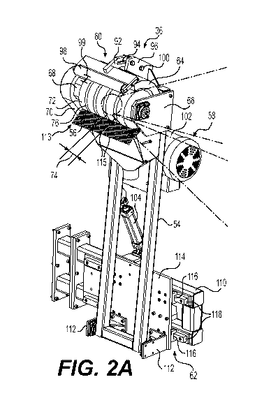
[010] FIG. 2A is a front, top perspective view of a pipe scuffing device
according to a disclosed embodiment;
[011] FIG. 2B is a schematic view of a flap wheel assembly according to a
to a disclosed embodiment;
[012] FIG. 2C is a schematic view of a wire wheel assembly according to a
disclosed embodiment;
[013] FIG. 3 is a rear, top perspective view of the pipe scuffing device of
FIG. 2; and
[014] FIG. 4 is a flow chart illustrating a method of controlling a pipe
scuffing device according to a disclosed embodiment.
DETAILED DESCRIPTION
[015] As discussed in further detail below, various embodiments of pipe
processing systems and methods are provided to process pipes in preparation
for
one or more downstream uses. Embodiments of the pipe processing system may
include a pipe scuffing device operable to remove a layer of material (e.g.,
contaminants) from an outer surface of a pipe. In some embodiments, stripping
of
the layer of material from the pipe may enable a molecular bond to be
established
between the stripped surface of the pipe and an applied outer wrap, thus
increasing
the likelihood of integration of the outer wrap and the pipe as compared to
wrapping
the pipe without first removing the layer of material. Further, the stripping
of the
- 3 -
CA 03048974 2019-06-28
WO 2018/125908 PCT/US2017/068513
layer of material may enable the outer surface of the pipe to be otherwise
processed.
For example, the outer surface may be painted. For further example, the outer
surface may be printed. Still further, the outer surface may be stripped to
enable
application of an adhesive (e.g., a sticker).
[016] Some disclosed embodiments of the pipe scuffing device may include
one or more features that enable scuffing of pipes with various contours and
configurations, such as a corrugated exterior. For example, in one embodiment,
a
flap wheel assembly may include one or more flap wheels configured to adapt to
the
corrugated shape of the pipe such that both the peaks and valleys of the
corrugated
pipe are scuffed. For further example, in some embodiments, the dimensions of
the
one or more flap wheels may be selected for compatibility with the dimensions
of the
corrugated pipe to increase the likelihood that the one or more flap wheels
follow the
contours of the pipe. These and other features of presently contemplated
embodiments are discussed in more detail below.
[017] Turning now to the drawings, FIG. 1 illustrates an embodiment of a
pipe processing system 10 in accordance with one embodiment of the present
disclosure. In the illustrated embodiment, the pipe processing system 10
includes a
stock of a plurality of pipes 12, a pipe scuffing system 14, a pipe
positioning system
16, and a pipe wrapping system 18. During operation, a pipe 14 from the
plurality of
pipes 12 may be positioned by the pipe positioning system 16 for scuffing by
the pipe
scuffing system 14 to produce a scuffed pipe 14' having a layer of material
removed,
as compared to pipe 14. For example, the scuffed pipe 14' may be free of
contaminants 20 present on the pipe 14 before scuffing. The scuffed pipe 14'
may
then be further processed by the pipe wrapping system 18 to apply an outer
wrap to
the scuffed pipe 14'.
- 4 -
CA 03048974 2019-06-28
WO 2018/125908 PCT/US2017/068513
[018] In the embodiment shown in FIG. 1, the pipe 14 is corrugated such
that the outer surface 22 is contoured and includes a series of corrugations
24. The
corrugations 24 may be disposed along the entire length of the pipe 14 or
along only
a portion of the corrugated pipe 14. Further, in other embodiments, the
corrugations
24 may be formed in any desired shape, such as spiral or annular corrugations,
depending on implementation-specific considerations. For example, the
corrugations 120 may spiral in the longitudinal direction around the
circumference of
the pipe 14 to enable greater structural integrity in implementations in which
a wall of
the pipe 14 is formed from plastic.
[019] In some embodiments, the corrugations 24 may have a pitch 26
defined by peaks 28 and valleys 30 that form the corrugations 24. As used
herein,
the pitch 26 may be a slope measurement measured between adjacent peaks 28
and/or adjacent valleys 30. The pitch 26 may vary depending on the given
implementation and may be determined, for example, based on a downstream use
of
the pipe. For example, in one embodiment in which the pipe 14 is used to
transport
sewage water, the pitch 26 may be approximately 3 inches (e.g., between 2.8
inches
and 3.2 inches). However, presently contemplated embodiments are not limited
to
any particular pitch 26, and the pitch 26 may vary in other implementations.
Further,
in other embodiments, the pipe 14 may not be corrugated. Indeed, in some
embodiments, the outer surface 22 may be smooth (e.g., without the presence of
the
peaks 28 and valleys 30) along some or all of the length of the pipe 14.
[020] In some embodiments, an end portion 32 of the pipe 14 may include a
connector 34 to enable coupling of two or more of the pipes 12 together. For
example, the connector 34 may be a bell (e.g., as in the illustrated pipe 14)
or a
spigot. In such an embodiment, the bell may be configured to surround and
contain
- 5 -
CA 03048974 2019-06-28
WO 2018/125908 PCT/US2017/068513
a spigot end of another pipe. In other embodiments, the connector 34 may be a
spigot configured to be received in a bell end of another pipe. In such
embodiments,
the spigot may have a smaller outer diameter than the bell, so that the spigot
may fit
into the bell. However, other types of connectors 34 may also be used with the
pipe
14. For example, any type of coupler known to those of ordinary skill in the
art may
be used to connect some or all of the pipes 12 together.
[021] Indeed, it should be noted that the illustrated pipe 14 is merely an
example subject to a variety of implementation-specific variations. It should
be
appreciated that the pipe scuffing system 14 and the pipe positioning system
16 may
be used with any suitable type of pipe 14, not limited to the embodiments
shown
here. Further, although the stock of the plurality of pipes 12 is shown
including three
pipes 14, any number of pipes may be included in other embodiments. Indeed,
the
pipe 14 may be sourced from the stock of the plurality of pipes 12, or from
any other
location upstream of the pipe scuffing system 14.
[022] Additionally, it should be appreciated that although the contaminants
20 are illustrated on the surface of the pipe 14, the contaminants 20 may or
may not
be visible to the naked eye, may be disposed at any location(s) along the
length of
the pipe 14 (e.g., in valleys 30, on peaks 28, on connector 34, etc.), may be
impurities present in an outer layer of the pipe 14, and so forth. For
example, in
some embodiments, the pipe 14 may undergo surface oxidation (represented by
contaminants 20). In some embodiments, oxidation may occur regardless of
whether the pipe stock 12 is stored indoors or outdoors. Because the surface
oxidation may impair the ability to bond anything desired to the surface of
the pipe
14, presently disclosed embodiments may enable removal of the oxidized layer.
- 6 -
CA 03048974 2019-06-28
WO 2018/125908 PCT/US2017/068513
Indeed, the contaminants 20 are merely illustrative of the impurities that may
be
present on or in the layer of material forming the outer surface 22 of the
pipe 14.
[023] Turning now to the pipe scuffing system 14, the system 14 may
include one or more components that enable removal of a layer of material from
the
outer surface 22 of the pipe 14. In the illustrated embodiment, the pipe
scuffing
system 14 includes a pipe scuffing device 36 and a control system 38
configured to
control the pipe scuffing device 36. During operation, the pipe scuffing
device 36 is
configured to remove a layer of material from the outer surface 22 of the pipe
14 to
remove one or more contaminants 20. The contaminants 20 removed via scuffing
may include, for example, rust, dirt, rocks, oxidation, water, other fluids or
liquids, or
any other contaminant. To that end, the pipe scuffing device 36 may include
one or
more abrasive elements configured to abrade the outer surface 22 of the pipe
14
when in contact with the pipe 14. For example, the pipe scuffing device 36 may
include grinding wheels, flap discs, flap wheels, sand paper, steel, wire
wheels, and
so forth.
[024] The illustrated control system 38 includes one or more processors 40
and memory 42. The one or more processors 40 (e.g., microprocessor(s),
application-specific integrated circuit (ASIC), field-programmable gate array
(FPGA),
etc.) may be configured to execute a control algorithm. By way of example, the
control algorithm may be provided as machine-readable encoded instructions
stored
on a machine-readable medium, such as the memory 42, and may provide control
signals for controlling operation of the pipe scuffing device 36. The control
signals
may control the pipe scuffing device 36 to selectively engage and disengage
one or
more abrasive elements with the pipe 14, for example, based on a desired level
of
scuff.
- 7 -
CA 03048974 2019-06-28
WO 2018/125908 PCT/US2017/068513
[025] The memory 42 may be a tangible, non-transitory, machine readable
medium. For example, the memory 42 may be volatile or non-volatile memory,
such
as read only memory (ROM), random access memory (RAM), magnetic storage
memory, optical storage memory, or a combination thereof. Furthermore, a
variety
of control parameters may be stored in the memory 42 along with code
configured to
provide a specific output (e.g., enable contact with pipe 14, disable contact
with pipe
14, etc.) to the pipe scuffing device 36 during operation. In some
embodiments, the
processor(s) 40 may also receive an input from a user interface through which
the
user may choose a process and/or input desired parameters (e.g., desired scuff
depth, pipe type, pitch of corrugations on the pipe 14, and so forth).
[026] The pipe positioning system 16 includes one or more components
configured to position the pipe 14 with respect to the pipe scuffing device 36
to
enable scuffing of the pipe 14. Specifically, in the illustrated embodiment,
the pipe
positioning system 16 includes a support 44 configured to support the pipe 14.
The
support 44 may include any suitable table, conveyor belt, frame, and so forth,
known
to those of ordinary skill in the art. A drive mechanism 46 is configured to
drive
movement of the support 44, the pipe 14, or both to enable a desired
positioning of
the pipe 14. The drive mechanism 46 may include motors, engines, circuitry,
etc. to
drive movement of the support 44 and/or the pipe 14. The drive mechanism 46
may
be controlled by a control system 48 including one or more processors 50 and
memory 52. The one or more processors 50 and memory 52 may include
components similar to those described above for the one or more processors 40
and
memory 42 in the pipe scuffing system 14. However, the control system 48 may
utilize such components to control the position of the pipe 14 relative to the
pipe
scuffing device 36. To that end, the control system 38 and the control system
48
- 8 -
CA 03048974 2019-06-28
WO 2018/125908 PCT/US2017/068513
may communicate via any known means (e.g., wirelessly, via wired connections,
etc.) to coordinate control of the pipe scuffing device 36 and the position of
the pipe
14. For example, in one embodiment, the control systems 38 and 48 may
coordinate
such that one or more flap or wire wheels of the pipe scuffing device 36
rotate in a
direction counter to a rotational direction of the pipe 14.
[027] Further, in some embodiments, the control systems 38 and 48 may
control the relative movement of the pipe 14 and the pipe scuffing device 36
to
enable the end 32 of the pipe 14 to be scuffed differently than the remaining
length
of the pipe 14. For example, the connector 34 may need to be processed for a
different period of time than the remainder of the length of the pipe 14, for
example,
to obtain a different level of scuff. For further example, in one embodiment,
during
processing of the end portion 32, the pipe 14 may be rotated about its
longitudinal
axis while the pipe scuffing device 36 is translated laterally.
[028] Once the pipe 14 is scuffed by the pipe scuffing device 36, a scuffed
pipe 14' may be ready for any desired downstream processing or use. For
example,
in the illustrated embodiment, the scuffed pipe 14' may be transferred to the
pipe
wrapping station 18 for application of an additional layer of material. For
example,
pipe wrapping station 18 may apply an outer wrap formed using fibers and/or
plastic.
In one embodiment of the applied outer wrap, fibers (e.g., fiberglass or
carbon fibers)
may be embedded in plastic. Polymers such as high density polyethylene (HDPE),
polypropylene (PP), or polyvinyl chloride (PVC) may be used as the plastic.
Other
fibers or plastics may also be used, depending on implementation-specific
considerations. Still further, the pipe wrapping system 18 may be configured
to
otherwise process the pipe 14'. For example, the pipe wrapping system 18 may
apply paint to the scuffed surface, apply an adhesive to the scuffed surface,
etc.
- 9 -
CA 03048974 2019-06-28
WO 2018/125908 PCT/US2017/068513
[029] The removal of a layer of material from the pipe 14 prior to application
of the outer wrap by pipe wrapping station 18 may offer one or more advantages
over systems that do not include pipe scuffing prior to wrapping. For example,
in
some embodiments, scuffing of the pipe 14 better enables a molecular bond to
be
formed between the applied outer wrap and the outer surface 22 of the pipe 14'
because the pipe 14' may have a reduced level of contaminants 20, which may be
present due to storage in the stock of pipes 12 for a period of time.
[030] FIGS. 2A and 3 illustrate front and rear perspective views,
respectively, of one embodiment of the pipe scuffing device 36. In this
embodiment,
the pipe scuffing device 36 includes a frame 54 that supports one or more
scuffing
and connectional components. Specifically, in the illustrated embodiment, the
frame
54 supports an abrasive wheel assembly 56, a drive system 58, and a guide
roller
assembly 60. The frame 54 is coupled to a positional system 62 configured to
enable the pipe scuffing device 36 to be positioned with respect to the pipe
14.
[031] In the illustrated embodiment, the frame 54 includes a partial cover
64
for the abrasive wheel assembly 56 and a panel 66 to which one end of a shaft
68 is
mounted. The other end of the shaft 68 is mounted to a pivot arm 70. In the
embodiment shown, the abrasive wheel assembly 56 is mounted to the shaft 68
such that a plurality of abrasive wheels 72 extends radially about the shaft
68. The
abrasive wheels 72 may be any suitable type of abrasive wheel 72. For example,
in
the embodiment shown in FIG. 2B, each abrasive wheel 72 is a flap wheel 79.
For
further example, in the embodiment shown in FIG. 2C, each abrasive wheel 72 is
a
wire wheel 81. However, in other embodiments, the abrasive wheel 72 is subject
to
implementation-specific variations.
-10-
CA 03048974 2019-06-28
WO 2018/125908 PCT/US2017/068513
[032] The abrasive wheel 72 has a width 74 and is disposed at a distance
76 from each adjacent abrasive wheel 72. In some embodiments, the distance 76
may be uniform between each of the abrasive wheels 72. However, in other
embodiments, the distance 76 may vary, depending on implementation-specific
considerations. For example, the distance 76 may be uniform between a subset
of
the abrasive wheels 72 with the last abrasive wheel 72 separated from an
adjacent
abrasive wheel 72 by a greater distance. Such a configuration may be desirable
in
implementations in which the subset of the abrasive wheels are configured to
scuff
the corrugations 24 of the pipe 14, and the distanced abrasive wheel is
configured to
scuff the connector 34 of the pipe 14.
[033] Each abrasive wheel 72 may include one or more features that enable
scuffing of the pipe 14. For example, in the embodiment illustrated in FIG.
2B, the
flap wheel 79 includes a plurality of flaps 78 having an abrasive material 80
configured to scuff the pipe 14. The abrasive material 80 may be integrated
into the
flaps 78 in any desirable manner, such as being disposed on edges 82 and/or
surfaces 84, integrated into the material forming the flaps 78, and so forth.
Further,
in some embodiments, the placement of the abrasive material 80 on the flap
wheel
79, e.g., along the edges 82 and the surfaces 84 of the flaps 78, may enable
the flap
wheel 79 to be used for a longer period of time, as compared to a continuous
wheel
not having flaps 78. For example, over time, the abrasive material 80 may
wear, and
by distributing this abrasive wear over multiple portions of multiple flaps
78, worn
areas may be present while the overall abrasive quality of the flap wheel 79
is
acceptable. Further, the abrasive material 80 may be any suitable abrasive
material
or composite, including, but not limited to, sand paper, wire brush (e.g.,
steel, brass),
-11-
CA 03048974 2019-06-28
WO 2018/125908 PCT/US2017/068513
ceramic brush, steel, rasp, flexible fingers with abrasive, aluminum oxide,
ceramic,
and so forth.
[034] Feature(s) of the abrasive wheel assembly 56 may enable the
assembly 56 to follow the contour of the pipe 14. For
example, in some
embodiments, each of the flaps 78 may be flexible to enable the flaps 78 to
adapt to
the contour of the pipe 14. For example, the diameter of the abrasive wheel
may
coincide with the depth of the corrugation in some embodiments. For further
example, the flaps 78 may bend to enable scuffing of both the peaks 28 and the
valleys 30.
[035] In the embodiment illustrated in FIG. 2C, the abrasive wheel
assembly 56 may include one or more wire wheels 81 having one or more wires
83.
In this embodiment, the one or more wires 83 may be bundled into wire groups
85
disposed circumferentially around the wire wheel 81.
However, in other
embodiments, the wires 83 may be arranged in any suitable manner. For example,
the wires 83 may be crimped. The wires 83 may be wound together and twisted to
form the wire groups 85. Indeed, the wires 83 may be arranged in any suitable
manner to form the abrasive wire wheel 81, not limited to the depicted
embodiment.
[036] Further, in some embodiments, the width 74 of the abrasive wheel 72
may be determined based on the pitch 26 of the corrugations 24 in the pipe 14.
For
example, in some embodiments, a relationship may exist between the pitch 26
and
the width 74 such that as the pitch 26 is reduced, the width 74 is also
reduced. More
specifically, in some embodiments, a ratio between the width 74 of the
abrasive
wheel 72 and the pitch 26 of the pipe 14 may be between approximately 1/3
(e.g.,
between .3 and .36) and approximately 1/6 (e.g., between .13 and .19). For
example, the pitch 26 may be 3 inches, and the width 74 may be 1 inch such
that the
-12-
CA 03048974 2019-06-28
WO 2018/125908 PCT/US2017/068513
ratio is 1/3. For further example, the abrasive wheel 72 may have a width of
1/2" to
1" and the corrugations may have a pitch of 3" to 6". The foregoing ratio may
offer
one or more advantages, such as by enabling the flaps 78 to follow the contour
of
the corrugations 30 of the pipe 14.
[037] Although the illustrated abrasive wheel assembly 56 includes multiple
abrasive wheels 72, in other embodiments, only a single abrasive wheel 72 may
be
used. Still further, in other embodiments, the abrasive wheel assembly 56 may
be
replaced with one or more cylindrical wheels disposed about the shaft 68 and
having
the abrasive material 80 thereon and/or integrated therein. Such an
arrangement
may be desirable in implementations in which the pipe 14 is not corrugated.
Indeed,
the pipe scuffing device 36 and abrasive wheel assembly 56 shown herein are
merely examples.
[038] The guide roller assembly 60 is coupled to the frame 54 via support
structure 90 and roller frame 92. Support structure 92 includes a track 94
along
which bracket 96 can move to enable positioning of a guide roller 98. The
bracket
96 is configured to move along the track 94 for positioning and to lock in
place at a
fixed position along the track 94 via fasteners 100. During a scuffing
operation,
when the abrasive wheel assembly 56 is positioned to contact the pipe 14, the
guide
roller 98 is configured to rest on the outer surface 22 of the pipe 14 and
passively
follow the contours of the pipe 14. The foregoing feature may enable the guide
roller
98 to increase the likelihood that only desired portions of the pipe 14 are
scuffed.
[039] Further, the guide roller 98 may also determine the depth of the
scuff.
Specifically, since the guide roller 98 is located above the abrasive wheel
assembly
56, it may determine the depth at which the abrasive wheels 72 can contact the
pipe
14. For example, a distance 99 between the guide roller 98 and the abrasive
wheel
-13-
CA 03048974 2019-06-28
WO 2018/125908 PCT/US2017/068513
assembly 56 may determine the depth at which the abrasive wheels 72 can scuff
by
fixing the relative distance between the abrasive wheel assembly 56 and the
pipe 14.
In some embodiments, the distance 99 may be predetermined before a scuffing
operation to set the scuff depth for the operation and/or may be readjusted to
control
the depth of the scuff of the pipe 14.
[040] In some embodiments, the pipe scuffing device 36 may include a
wiping device 113, as shown in FIG. 2A. In one embodiment, the wiping device
113
may be a brush having bristles 115. The wiping device 113 may cooperate with
the
abrasive wheel assembly 56 to clean the outer surface of the pipe 14 as it is
scuffed
(e.g., to remove the contaminants 20 from the surface of the pipe 14 after the
abrasive wheel assembly 56 dislodges the contaminants 20). The wiping device
113
may also enable containment of the contaminants 20 during operation. In some
embodiments, the wiping device 113 may be positioned on the downstream side of
the abrasive wheel assembly 56, as shown in FIG. 2A, to allow the abrasive
wheels
72 to remove material but to help catch any debris and to wipe the
corrugations.
However, the location and quantity of the wiping device 113 is merely
illustrative.
Indeed, in some embodiments, the wiping device 113 may instead be located on
the
upstream side of the abrasive wheel assembly 56 (e.g., adjacent the guide
roller 98).
In still further embodiments, the wiping device 113 may include two wiping
devices,
one located downstream of the abrasive wheel assembly 56 and the other located
upstream of the abrasive wheel assembly 56. Further, in some embodiments, the
wiping device 113 may also be flexible such that it follows the contours of
the pipe
14.
[041] The drive system 58 is configured to drive the movement of the
abrasive wheel assembly 56. To that end, the drive system 58 in the
illustrated
-14-
CA 03048974 2019-06-28
WO 2018/125908 PCT/US2017/068513
embodiment includes a drive motor 102 and an engage/disengage cylinder 104.
During operation, the drive motor 102 and the cylinder 104 cooperate under
control
of the processor(s) 40 to rotate the shaft 68 upon which the abrasive wheel
assembly 56 is disposed. The processor(s) 40 may also control the drive motor
102
and the cylinder 104 to control movement of the abrasive wheel assembly 56
toward
and away from the pipe 14 to selectively engage and disengage the abrasive
wheel
assembly 56 to and from the pipe 14. For example, the processor(s) 40 may
control
the cylinder 104 to an engage position such that the pivot arm 70 moves the
abrasive wheel assembly 56 toward the pipe 14, and control the cylinder 104 to
a
disengage position to disengage the abrasive wheel assembly 56 from the pipe
14.
[042] The positional system 62 is configured to enable the position of the
abrasive wheel assembly 56 to be altered along the longitudinal axis of the
pipe 14.
In the illustrated embodiment, the positional system 62 includes a frame 110
configured to be mounted to the support 44 for the pipe 14, or any other
suitable
structure in the pipe positioning system 16. The frame 54 of the pipe scuffing
device
36 is configured to couple to the frame 110 of the positional system 62 via
brackets
112 and plate 114. The plate 114 includes tracks 116 configured to receive
rails 118
disposed on the frame 110. A slide cylinder 120 is configured to enable
movement
of the frame 54 along the length of the tracks 116 to longitudinally position
and
reposition the abrasive wheel assembly 56. The foregoing feature may enable
the
abrasive wheel assembly 56 to scuff a first longitudinal position along the
length of
the pipe 14 and be moved to additional longitudinal positions to scuff
additional
portions along the length of the pipe 14.
[043] In some embodiments, it may be desirable for the abrasive wheel
assembly 56 to move longitudinally in the direction of the axis of the pipe 14
to
-15-
CA 03048974 2019-06-28
WO 2018/125908 PCT/US2017/068513
enable greater operational flexibility. For example, translational movement
may be
desirable at the end of the scuffing cycle so that the abrasive wheels 72
remain in
contact with the exterior of the pipe 14. For example, in one embodiment, the
rails
118 may be equal to or greater than the length of the pipe 14. In this
embodiment,
the longitudinal movement of the abrasive wheel assembly 56 may enable the
pipe
14 to be scuffed without the need to translate the pipe 14. In another
embodiment,
the rails 188 may be a length equal to half the length of the abrasive wheel
assembly
56. In this embodiment, the translational movement may be used to keep the
abrasive wheel assembly 56 in contact with the pipe 14 when reaching the end
of a
scuffing cycle.
[044] FIG. 4 is a flow chart illustrating an embodiment of a method 130
that
may be used to control the pipe processing system 10 in accordance with one
embodiment. The method 130 may be performed by the processor(s) 40 in the pipe
scuffing system 14, the processor(s) 50 in the pipe positioning system 16, a
combination thereof, or any of the processor(s) 40, 50 in combination with
other
control systems.
[045] In the illustrated embodiment, the method 130 begins when a pipe
scuffing operation is initiated (block 132). The method 130 includes receiving
a
desired level of scuffing (block 134). For example, the processor executing
the
method 130 may receive a signal indicating that a user would like to abrade or
gouge
the pipe 14. For further example, a user may indicate a depth of the layer of
material
to be removed from the pipe via scuffing. In some embodiments, the depth of
the
layer of material removed via scuffing may be automatically determined based
on a
length of time the pipe 14 has been stored after being produced.
-16-
CA 03048974 2019-06-28
WO 2018/125908 PCT/US2017/068513
[046] The method 130 may also include setting a rotation speed of the
abrasive wheel assembly 56 based on the desired scuff level (block 136). For
example, the rotation speed may be set higher for deeper scuffs and lower for
shallower scuffs. The method 130 may further include controlling the pipe
scuffing
device 36 to engage the abrasive wheel(s) 72 with the pipe 14 (block 138). For
example, the engage cylinder 104 may be activated to reposition pivot arm 70
to
move the abrasive wheel assembly 56 toward the pipe 14. The method 130 then
includes controlling the position of the pipe 14, the pipe scuffing device 36,
or both to
effectuate relative rotations between the pipe 14 and the abrasive wheel
assembly
56 (block 140). For example, in one embodiment, the abrasive wheel assembly 56
may be rotated in a first rotational direction (e.g., clockwise), and the pipe
14 may be
rotated, e.g., via support 44, in a second rotational direction (e.g.,
counterclockwise)
counter to the first rotational direction. The opposite spin directions may
enable
more efficient scuffing in certain implementations. However, in other
embodiments,
the pipe 14 and the abrasive wheel assembly 56 may rotate in the same
direction.
Still further, in some embodiments, only one of the abrasive wheel assembly 56
and
the pipe 14 may rotate.
[047] The method 130 may further query whether a desired number of
rotations are reached (block 142). For example, in some embodiments, the pipe
14
and the abrasive wheel assembly 56 may each be controlled to complete one 360
degree rotation before disengagement. However, in other embodiments, multiple
rotations may be completed before disengagement. In the illustrated method
130, if
the desired number of rotations is not yet reached, the pipe scuffing device
maintains
engagement with the pipe 14. However, if the desired number of rotations is
-17-
CA 03048974 2019-06-28
WO 2018/125908 PCT/US2017/068513
reached, the method 130 includes controlling the pipe scuffing device 36 to
disengage the abrasive wheel(s) 72 from the pipe 14 (block 144).
[048] The method 130 may query whether scuffing is complete (block 146).
If scuffing is complete, the operation is ended (block 148). Completion of
scuffing
may be determined in any suitable manner. For example, scuffing may be
complete
when it is automatically or manually determined that the entire desired length
of the
pipe 14 has been scuffed. For further example, in one embodiment, the presence
of
the connector 34 may be determined, and scuffing may be determined to be
complete when the connector 34 is reached.
[049] If scuffing is not complete, the method 130 may include adjusting the
relative lateral position between the abrasive wheel(s) 72 and the pipe 14
(block
150). For example, slide cylinder 120 may be activated to move the frame 54
along
the length of the tracks 116 to move the abrasive wheel assembly 56. In other
embodiments, the support 44 for the pipe 14 may be adjusted to reposition the
pipe
14 with respect to the abrasive wheel assembly 56.
[050] The method 130 may query whether a disengagement region of the
pipe 14 is reached (block 152). If a disengagement region is reached, the
method
130 may include adjusting the relative position between the abrasive wheel(s)
72
and the pipe 14 (block 154) to avoid the disengagement region. For example,
the
connector 34 may be set as a disengagement region. When the connector 34 is
detected, the method 130 may proceed to another region, thus avoiding the area
it is
not desirable to scuff. However, in other embodiments, the connector 34 may be
included in the region to be scuffed.
[051] It should be noted that the products and/or processes disclosed may
be used in combination or separately. Additionally, exemplary embodiments are
-18-
CA 03048974 2019-06-28
WO 2018/125908 PCT/US2017/068513
described with reference to the accompanying drawings. Wherever convenient,
the
same reference numbers are used throughout the drawings to refer to the same
or
like parts. While examples and features of disclosed principles are described
herein,
modifications, adaptations, and other implementations are possible without
departing
from the spirit and scope of the disclosed embodiments. It is intended that
the prior
detailed description be considered as exemplary only, with the true scope and
spirit
being indicated by the following claims.
[052] The examples presented herein are for purposes of illustration, and
not limitation. Further, the boundaries of the functional building blocks have
been
arbitrarily defined herein for the convenience of the description.
Alternative
boundaries can be defined so long as the specified functions and relationships
thereof are appropriately performed. Alternatives (including equivalents,
extensions,
variations, deviations, etc., of those described herein) will be apparent to
persons
skilled in the relevant art(s) based on the teachings contained herein. Such
alternatives fall within the scope and spirit of the disclosed embodiments.
Also, the
words "comprising," "having," "containing," and "including," and other similar
forms
are intended to be equivalent in meaning and be open ended in that an item or
items
following any one of these words is not meant to be an exhaustive listing of
such
item or items, or meant to be limited to only the listed item or items. It
must also be
noted that as used herein and in the appended claims, the singular forms "a,"
"an,"
and "the" include plural references unless the context clearly dictates
otherwise.
-19-