Note: Descriptions are shown in the official language in which they were submitted.
85403812
1
Perfusion device
The invention concerns a perfusion device for a cell culture
container, in particular a petri dish, having the features as described
herein.
A method of investigating the behaviour of cells or microorganisms
involves growing cultures in cell culture containers (so-called culture
dishes) and then observing the effects of a nutrient medium which is
possibly mixed with medicaments or other test substances. The cell
culture containers involve dish-shaped containers like for example petri
dishes, at least partially plate-shaped containers like for example multi-
well plates or also other containers used for the cultivation of cells or
microorganisms.
After the cells are sown into the cell culture container the cells begin
to multiply until the entire growth surface of the container is covered with
cells. In that case the cells with the container, in the case of a static
culture (so-called "batch method") are left at rest in a special incubator
which at body temperature constantly holds a vapour-saturated
atmosphere of 95% air and 5% carbon dioxide. Thus the cells statically
coated with the nutrient medium receive oxygen by passive diffusion
across a gap of the cover of the container, which is not disposed thereon
in sealed relationship.
The main problem in that respect are the ambient conditions in
static cultures, which vary continuously over the entire culture period.
Nutrient substances are absorbed by the cells from the freshly coated
nutrient medium and given back into the nutrient medium again
"metabolised" in chemically modified form. In that respect the
metabolically active cells in the first 12 to 24 hours of the nutrient surplus
Date Recue/Date Received 2020-09-03
85403812
la
supply require a very great deal of oxygen for the oxidative breakdown of
glucose and amino acids, in which case a diffusion-induced oxygen
gradient rapidly occurs in the nutrient medium which is millimeter-thick
coated. The cells frequently become hypoxic and increasingly adapt their
metabolism to anaerobic
Date Recue/Date Received 2020-09-03
CA 03049060 2019-07-02
2
glycolysis. In that situation glucose no longer becomes CO2 but is almost
only broken down to lactate and eliminated. Usually the nutrients which
are contained in the limited volume of coated nutrient medium are
completely consumed after 24 to 48 hours while the nutrient medium at the
same time in enriched with excreted cell metabolic products. By virtue of
the insufficient supply of nutrients linked thereto the cells have shut down
their metabolism, in which case the initially slightly basic nutrient medium
generally by virtue of lactate elimination becomes slightly acid and slightly
toxic, for example as a consequence of enrichment with ammonia from the
breakdown of glutamine.
In addition the cells are energetically weakened in anaerobic
glycolysis and the oxygen content in the medium moves back into the
saturation range again. In that situation an excess supply of oxygen can
even suddenly occur, which in the absence of nutrients is also no longer
required or used. That damages the cells because of increased immune
deficiency by virtue of radical catcher molecules which are scarcely still
present, in relation to oxygen radicals which are constantly re-forming.
When the nutrient medium is used it is sucked away and the cells coated
with newly fresh nutrient medium. The superfluity-hunger cycle begins
afresh.
In static cultures, by virtue of that cyclic culture non-homogeneity, it
is scarcely possible to carry out reliably reproducible experiments with
uniform validity. For example the timing is of extreme significance for the
delivery of medicaments. If the medicaments are supplied at the beginning
of the feed cycle the cells are in a good energy state and highly
metabolically active. They accordingly react entirely differently as soon as
the metabolism switches over to the hunger state which subsequently
becomes increasingly worse. In summary it can be found that cultivated
cells in the classic batch method do not involve homogeneous culture
conditions at any time in the culture period. It is correspondingly difficult
to achieve significant test results in relation to medicament effects in
vitro.
Nonetheless static cultures are frequently used for experiments as this
involves a simple system entailing low costs and high sample throughput.
CA 03049060 2019-07-02
3
To overcome the disadvantages of static methods, so-called
perfusion culture methods have become known in the state of the art,
which have a number of scientifically proven advantages over the classic
method of cultivating cells. For example, similarly to the situation in the
body, care is taken to ensure that the cultured cells are exposed to uniform
environmental conditions over the entire culture period. Conventional
perfusion devices have special perfusion chambers which are slightly
overpressure-tight and in which the cells are cultivated. Nutrient medium is
fed from a nutrient medium reservoir to the perfusion chamber by way of a
hose system and a pump. The reservoir is generally brought to body
temperature and gassed with an air-0O2 mixture, similarly to the incubator.
In that way care is taken to ensure that the cells are fed continuously fresh
medium as required with a regulatable flow rate through the perfusion
chamber. Constant environmental conditions thus obtain over the entire
culture period. That in turn ensures meaningful and reproducible test
results which can be achieved very substantially independently of the
administration timing of test substances.
US No 8 501 462 discloses a perfusion device having a multi-well
plate in which there are provided a plurality of inserts which each have a
perfusion region. Arranged at the underside of the inserts is a gas-
permeable membrane, wherein the membrane at the side towards the
respective insert has projections, by means of which the membrane is
spaced from the underside of the insert. The intermediate space between
the projections forms a flow passage, through which the nutrient can flow,
and in so doing diffuses by way of the membrane to the cell cultures. A
disadvantage with that configuration is that the nutrient medium flows for
the major part directly from the feed line to the discharge line. In addition
at the polygonal edges of the inserts this arrangement involves differing
nutrient availability, by virtue of a different flow speed of the nutrient
medium in the edge region and by virtue of the resulting turbulence there.
For that reason there are large zonal differences in terms of availability of
the nutrients, and they are detrimental for homogeneous growth of the cell
cultures and therefore unwanted.
CA 03049060 2019-07-02
4
US No 2013/0068310 concerns a perfusion device of a multi-layer
structure, having a multi-well plate. In that arrangement disposed in a
distribution layer and in a gradient layer are micropassages serving to
produce a concentration gradient of nutrient medium above the cell culture.
The nutrient medium is delivered by way of a porous membrane. Various
geometrical arrangements are provided for the micropassages of the
gradient and distribution layers, wherein the micropassages are connected
by way of a network to connecting passages. That results in a field-like
concentration gradient of nutrient medium, wherein this involves high flow
compression of the nutrient medium at the direction-changing points and a
constant flow density occurs only in partial regions. It is therefore also not
possible with this diffusion device to provide homogeneous culture
conditions for the cell cultures by virtue of detrimental nutrient supply.
That is extremely undesirable for test series with verifiable results.
A disadvantage with the perfusion devices known in the state of the
art is in particular their complexity. Examples of such complex perfusion
devices are disclosed in WO 82/03227, WO 02/24861, WO 2015/027998,
US 6 670 170, DE 4305405, DE 19742163 and DE 10118905. The
consequence of this is that one-way systems for perfusion cultures are
scarcely obtainable and if so then only with such small growth surfaces for
the cell cultures that only special individual investigations on cells are
meaningful and possible. In the case of
multi-way systems in turn
operation and here in particular sterile assembly require a great deal skill
by virtue of the complex devices, and that usually results in a low level of
sample throughput.
WO 2007/124481 and WO 2011/011350 concern nnicrofluid devices,
wherein nutrient and test substances are fed to individual cells by way of
micropassages. In part the flow of the substances is produced exclusively
by the capillary forces acting in the closed micropassages. In that case the
investigation objects are either incorporated into the wall of the
micropassage or are in holders specifically arranged for that purpose. As
investigations can only be carried out on individual objects with those
devices the nnicrofluid devices are of a closed structure and have an
85403812
integrated perfusion device which cannot be replaced. In particular only
dynamic but not static cell cultures can be investigated with those devices.
In addition the investigation objects are in part flushed out of the
nnicrofluid device by virtue of the configuration of the nnicropassages,
5 whereby homogeneous culture conditions for cell cultures are also made
impossible.
To sum up the perfusion culture method with the perfusion devices
known in the state of the art is technically much more complicated and
thus more expensive to operate than the conventional batch method,
wherein in particular the sterile assembly and the more time-consuming
handling of the existing devices has resulted in a lower level of acceptance
of this alternative which in itself is physiologically more expedient, to
classic in vitro models.
Therefore the object of the invention is to provide a perfusion device
with which the disadvantages of the known devices for the perfusion
culture method are avoided. In addition the invention seeks to provide a
possible way of converting existing cell culture containers for static
cultures easily into a device with which static cultures can be converted
into perfusion cultures and cultivated with the perfusion culture method.
In that respect the aim is to provide homogeneous culture conditions for
the cell cultures, wherein the perfusion device can be inserted into the cell
culture container without damaging the cells of the cell culture.
In one aspect, the present invention provides a perfusion device for
a cell culture container, comprising at least one inlet opening for the
supply of nutrient medium and at least one outlet opening for the
discharge of unused nutrient medium, wherein there is provided at least
one perfusion region for the delivery of nutrient medium to cell cultures,
which is connected to the inlet opening by way of a supply line and to the
Date Recue/Date Received 2020-09-03
85403812
5a
outlet opening by way of a discharge line, wherein the perfusion region
can be inserted into the cell culture container, wherein the perfusion
region comprises a geometrical structure which connects the supply line
and the discharge line in the form of an at least partially spiral-shaped
passage through which the nutrient medium can flow, wherein the
geometrical structure is spaced from the bottom of the cell culture
container in the inserted state.
In another aspect, the present invention provides a set including a
cell culture container and the perfusion device as described herein,
wherein the perfusion region can be inserted into the cell culture
container.
With the perfusion device according to the invention static cell
cultures (so-called "batch cultures", "staple culture dishes" or "staple
culture plates") can be upgraded or converted to so-called "perfusion
cultures" in the shortest time. Conversion back into a static cell culture is
also quite easily possible. For that purpose the perfusion device according
to the invention has a perfusion region which is connected by way of
supply line to at least one inlet opening and by way of a discharge line to
at least one outlet opening. If the perfusion device has a plurality of inlet
openings and/or a plurality of outlet openings a plurality of supply lines
and discharge lines can be provided, which serve to connect the inlet
openings and/or the outlet openings to the perfusion region.
Date Recue/Date Received 2020-09-03
CA 03049060 2019-07-02
6
The at least one inlet opening serves for the supply of nutrient
medium for the cell cultures to be investigated, nutrient medium which has
not been used and possibly excretion substances of the cell cultures are
discharged by way of the at least one outlet opening.
The perfusion device has a perfusion region, by way of which
nutrient medium is delivered to the cell cultures to be investigated, the cell
cultures being arranged in a cell culture container into which the perfusion
region can be fitted. The term cell culture container in accordance with the
invention is used in this respect to denote conventional dish-form
containers which are known in the state of the art like for example petri
dishes and at least partly plate-shaped containers like for example multi-
well plates and other containers, which are used for the cultivation of
microorganisms and for cell culture, in particular cell culture containers
with
a removable cover.
In that respect the cells, as is generally usual for static cell cultures,
can firstly be seeded in the cell culture container and covered with nutrient
medium. As soon as the cells are attached to the dish or plate bottom of
the cell culture container static culture can be converted into a perfusion
culture by the perfusion region of the perfusion device according to the
invention being fitted into the cell culture container.
The inlet opening can be connected to a nutrient medium reservoir.
The nutrient medium is fed by way of the supply line to the perfusion
region, by way of which it is made available to the cell cultures in the cell
culture container. In the case of a plurality of inlet openings nutrient
medium can be supplied to the perfusion region by way of a plurality of
supply lines. If the supply lines end at different locations in the perfusion
region then particularly homogeneous delivery of the nutrient medium can
be achieved, depending on the respective distribution of the supply lines.
With a plurality of inlet openings it is also possible to supply nutrient
medium by way of one inlet opening while nutrient media mixed with
medicaments or other test substances are supplied by way of another inlet
opening. In that way tests can be particularly easily carried out.
CA 03049060 2019-07-02
7
The perfusion region has a geometrical structure, by way of which
the nutrient medium is made available to the cell cultures. In the inserted
state of the perfusion region the structure is towards the cell cultures. The
structure provides a passage which connects the supply line and the
discharge line and through which the nutrient medium can flow. In that
case the geometrical structure is of such a configuration that the passage
formed covers large parts of the perfusion region. In that way it is possible
on the one hand for regions of large area to be made available, through
which the nutrient medium flows. Accordingly regions of large area are
also made available with nutrient medium for the cell cultures in the cell
culture container. On the other hand the passage causes a flow of the
nutrient medium at a certain flow rate so that the disadvantages of static
cell culture methods do not arise, but in return there are the advantages of
perfusion culture methods.
The passage can be in the form of a groove or channel, wherein ¨
depending on the respective geometrical structure ¨ variable groove depths
and groove widths but also at least partially or entirely constant groove
depths and/or groove widths are possible. Insofar as the geometrical
structure in the inserted condition is spaced from the bottom of the cell
culture container it is possible to insert the perfusion device without
damaging or indeed destroying the cell cultures. In that way static cell
cultures can be converted into perfusion cultures without adversely
affecting the cells. The spacing of the outermost region of the geometrical
structure relative to the bottom of the cell culture container in the inserted
state of the perfusion region corresponds in that case to the spacing of the
passage or the geometrical structure relative to the bottom of the cell
culture container.
It is possible by means of the invention to use the petri dishes
employed for conventional cell culture methods, but also other cell culture
containers like for example multi-well plates, for perfusion methods, by
using a perfusion device according to the invention, whose perfusion region
is fitted into the cell culture container, instead of the conventionally
employed cover. The classic formats of cell culture containers can thus be
CA 03049060 2019-07-02
8
retained. By removal of the perfusion device the system can be converted
from a perfusion culture back into a conventional static culture. The
perfusion device according to the invention is very simple to handle and
there is no disadvantage in respect of time for a perfusion culture method
operated therewith in comparison with the batch method.
Further advantageous configurations of the invention are defined in
the appendant claims.
In an advantageous embodiment the perfusion device is in the form
of a cover for the cell culture container. In that case the normal cover, for
example the normal petri dish cover or the normal covering of the multi-
well plate can be removed and replaced by the perfusion device according
to the invention. In that case the entire perfusion device can be integrated
into the cover which is easy to change. Conversion of a static cell culture
into a perfusion culture is therefore easily possible by replacing the cover
of
the cell culture container. Preferably it is further provided that the
perfusion device has a holding element, with which the perfusion device is
removable from the cell culture container. Replacement of the cover of the
cell culture container is thus possible with a single handhold.
Preferably it is provided that the passage and/or the geometrical
structure of the perfusion region in the inserted state is or are arranged
substantially parallel to the bottom of the cell culture container. In that
way it is possible to provide that the nutrient medium flowing through the
passage is at a substantially constant spacing relative to the cell cultures
and thus homogeneous environmental conditions are made available for
the cell cultures. In that respect in an embodiment it is provided that the
geometrical structure in the inserted state is at a spacing of less than 250
pm relative to the bottom of the cell culture container, preferably a spacing
of between 20 pm and 100 pm being provided.
In a further embodiment the perfusion region has a seal for sealingly
closing off the cell culture container. For example the seal is arranged at
the edge of the perfusion region and in the inserted state seals off the cell
culture container, for example at the peripheral surface of a petri dish. It
is
CA 03049060 2019-07-02
9
possible in that way with simple means to achieve the overpressure-tight
conditions as in a conventional complicated perfusion chamber.
In an embodiment the perfusion device has a cover plate on which a
holding element can be arranged for removal thereof. The perfusion region
can be arranged spaced from the cover plate. If the perfusion region itself
is plate-shaped it can be provided that the perfusion region and the cover
plate are arranged parallel. By virtue of a spacing the perfusion region can
also be used in relation to cell culture containers in which the growth
surface for the cell cultures is at a greater spacing relative to the upper
edge of the container. In addition, with such perfusion regions, it is
particularly easy to provide for sealing closure to the cell culture
container.
The perfusion region itself can be at least partially or also entirely of
a circular or cylindrical configuration. Such perfusion regions are inserted
into circular petri dishes with cylindrical peripheral surfaces or for example
into multi-well plates having cylindrical chambers for the cell cultures. It
will be noted however that with cell culture containers of different shapes,
for example square containers, it is also possible for the perfusion region to
be of a shape adapted to the cell culture container and to be for example
rectangular.
It is preferably provided that the passage formed by the geometrical
structure is continuous and for example in the form of a continuous groove
or channel connects the supply line to the discharge line. In that respect it
can be provided that the end of the supply line, disposed in the perfusion
region, and/or the end of the discharge line, disposed in the perfusion
region, opens directly into the passage. With a continuous passage it is
more easily possible to provide for a complete circulation of the nutrient
medium.
The passage is at least partially of a spiral shape, wherein in an
embodiment the passage is entirely of a spiral configuration. In that way it
is possible to cover large regions of the perfusion device, wherein uniform
nutrient supply and thus homogeneous culture conditions are afforded.
The supply line can open into an end of the spiral-shaped part while the
discharge line connects at the other end of the spiral-shaped part.
CA 03049060 2019-07-02
Particularly in the case of circular perfusion regions a large part of the
surface of the perfusion region can be covered by a spiral passage. If the
growth surface of the cell cultures in the cell culture container
substantially
corresponds to the area of the perfusion region that means that a large
5 region of the growth surface is covered by the nutrient medium flowing
through the passage. It can be provided that the passage is entirely of a
spiral configuration. It is however also possible for only a certain part of
the passage to be of a spiral configuration.
In a preferred embodiment the geometrical structure is in the form
10 of a web (in other words: a channel wall) arranged on the perfusion
region.
In that case the passage can extend between the web or in the form of a
space region which is afforded between the web. The spacing of the
outermost region of the web relative to the bottom of the cell culture
container in the inserted state of the perfusion region corresponds in that
case to the spacing relative to the bottom of the cell culture container.
In a preferred embodiment the web has curved side flanks. The side
flanks of the web can be connected in that case by way of a flat connecting
region or however they can converge to a more or less sharp edge. A
curved transition without sharp edges is also possible. Oxygen gradients
which represent a problem in particular in static cell culture methods can be
avoided by the curved side flanks.
The passage can be in the form of a groove or channel between the
geometrical structure in the form of the web. The web forms the wall of the
passage. With curved side flanks that can afford a passage which is of
curved cross-section, in particular a semicircular passage. Other geometries
like for example partly elliptical or passages which are oval in some other
way are however also possible. In particular there can be a varying
curvature. At its outermost region it can be provided that the web is also
curved, for example curved outwardly, so that the transition between two
grooves does not have any sharp edges to avoid gradient formation.
In a preferred embodiment a passage is downwardly open. In that
way the nutrient medium can pass directly and unimpededly to the cell
structures, whereby once again gradient formation can be avoided.
CA 03049060 2019-07-02
11
In an embodiment of the invention the cross-sectional area of the
passage is between 2.5 mm2 and 20 mm2, preferably between 8 mm2 and
16 mm2. The height of the geometrical structure or the height of the web
is between 0.5 mm and 5 mm, preferably between 2 mm and 2.5 mm. The
term height of the geometrical structure or the height of the web is
intended in that respect to denote the depth of the passage. That is that
dimension which in the inserted state of the perfusion device is arranged
perpendicularly to the bottom of the cell culture container and is measured
from the uppermost point of the web to the deepest point of the groove.
The passage formed by the geometrical structure permits a flow
speed for the nutrient medium. The passage can be of such a configuration
as to permit media flows of up to 10 ml/min, wherein media flows of
between 0.2 ml/h and 1 ml/h are preferred to avoid cell-damaging shearing
forces. The passage permits homogeneous perfusion over the entire
growth surface without gradient zoning. That occurs in particular when
using a curved passage shape.
The geometrical structure can be of such a configuration that the
nutrient medium diffuses between the grooves. That can avoid a build-up
of pressure in the system while microcirculation and circulatory flow of the
nutrient medium is promoted.
For the same purpose the web and/or the passage can have devices
serving for flow deflection for the nutrient medium flowing therethrough.
This can involve small barriers or chicanes. The flow deflection devices also
improve microcirculation and circulatory flow of the nutrient medium in the
passage. In addition the flow transfer of unused nutrient medium is
optimised so that this affords improved gas and nutrient substance
availability for the cultivated cells.
The inlet opening and/or the outlet opening can be connected to a
pump with which the flow of the nutrient medium is produced and fresh
nutrient medium is supplied and used nutrient medium is discharged.
Possibilities here are for example perfusion pumps, peristaltic pumps,
injection pumps and the like.
CA 03049060 2019-07-02
12
A further embodiment provides that the perfusion device has a first
and a second inlet opening for the supply of nutrient medium and a first
and a second outlet opening for the discharge of as yet unused nutrient
medium. In that case for example nutrient medium can be supplied in the
first inlet opening while medicaments or other test substances are supplied
in the second inlet opening. It is however also possible that exclusively
nutrient medium or nutrient medium already mixed with medicaments or
test substances is supplied both with the first and also with the second inlet
opening. In that case the perfusion region is connected to the first inlet
opening by way of a first supply line and to the second inlet opening by
way of a second supply line. It is however also conceivable for the first and
second inlet openings to open into the same supply line. The perfusion
region is connected to the first outlet opening by way of a first discharge
line and to the second outlet opening by way of a second discharge line. It
is however also conceivable for both the first and also the second outlet
openings to open into a discharge line. In addition is basically also possible
to provide more than two inlet openings and more than two outlet
openings. In addition the number of inlet openings does not have to
coincide with the number of outlet openings.
By the provision of a plurality of inlet openings it is possible to still
more homogenise the supply of the nutrient medium, for example by the
supply lines being suitably distributed on the perfusion region. In addition,
zonal investigations can be carried out by a plurality of inlet openings, by
different nutrients or different medicaments or other test substances being
supplied by way of the individual openings, then being passed to the
perfusion region by way of the corresponding supply lines and made
available there to the cell cultures. Different cell culture reactions then
occur in the corresponding zones.
With at least two inlet and two outlet openings it is preferably
provided that the geometrical structure connects the first supply line to the
first discharge line in the form of a first passage and the second supply line
to the second discharge line in the form of a second passage. In that
respect it is preferably provided that the first passage and the second
CA 03049060 2019-07-02
13
passage have the nutrient medium flowing therethrough in opposite
relationship. The
circulatory flow of the nutrient medium and the
microcirculation are further improved by the opposite flow.
To be able to cover large-area regions of the perfusion region it can
be provided that the first and second at least partially spiral-shaped
passage are at least entirely of a spiral shape, with oppositely directed
spirals being preferred.
The invention further concerns a set including a perfusion device as
described above and a cell culture container, in particular a petri dish.
In the case of a cell culture container having a plurality of chambers
for the cultivation of cells, in particular in the form of a multi-well plate,
it
can be provided that the perfusion device has a plurality of perfusion
regions, wherein a respective perfusion region can be inserted in a
chamber.
Further details and advantages of the present invention will be
described more fully hereinafter by means of the specific description with
reference to the drawings in which:
Figures 1 shows a diagrammatic view of a device for static cell
culture according to the state of the art,
Figures 2a ¨ 2c show a perspective view, a side view and a plan view
from below of a perfusion device according to the invention,
Figures 3a and 3b show two cross-sectional views of the perfusion
device according to the invention,
Figures 4a ¨ 4g show a perspective view, two side views, a plan view
from below, a plan view from above and two cross-sectional views of a
further embodiment of a perfusion device according to the invention,
Figures 5a ¨ 5g show a perspective view, two side views, a plan view
from below, a plan view from above and two cross-sectional views of a
further embodiment of a perfusion device according to the invention,
Figures 6a ¨ 6h show a perspective view, two side views, a plan view
from below, a plan view from above and two cross-sectional views of a
further embodiment of a perfusion device according to the invention,
CA 03049060 2019-07-02
14
Figures 7a - 7c show diagrammatic views of devices for flow
deflection for the nutrient medium, and
Figures 8a and 8b show diagrammatic views of two sets according to
the invention.
Figure 1 shows a device for static cell culture, wherein cells 11 are
arranged at the bottom of a cell culture container 3 in the form of a petri
dish and are coated over with nutrient medium 4. The cell culture
container 3 is closed with a cover 13.
The cover 13 can be replaced by a perfusion device 1 according to
the invention whereby the existing cell culture container 3 together with
cells 11 already cultivated therein can be used for the perfusion culture
method.
The perspective view in Figure 2a shows a perfusion device 1
according to the invention having a cover plate 9 and a perfusion region 2
spaced therefrom. The perfusion region 2 like the cover plate 9 is of a
round circular configuration and can be inserted for example in a cell
culture container 3 in the form of a circular petri dish. The Figure further
shows the inlet opening 15 by way of which nutrient medium 4 can be
supplied and the outlet opening 16 by way of which unused nutrient
medium or the excretion substances of the cells 11 can be discharged.
Figure 2b shows a plan view from below of the perfusion device 1.
Shown in the middle of the circular perfusion region 2 is the supply line 5,
by way of which the perfusion region 2 is connected to the inlet opening
15. The supply line 5 opens into the spiral passage 8 formed by the
geometrical structure 7 in the form of a spiral web. Large regions of the
perfusion region 2 are covered by the spiral shape of the passage 8 and
can have the nutrient medium 4 flowing therethrough. The perfusion
region 2 with the geometrical structure 7 arranged thereon represents a
perfusion screw spiral, wherein the passage 8 is formed by the grooves of
the screw spiral.
In this embodiment the supply line 5 and the discharge line 6 are at
least partially in the form of tube connections, the tubes permitting spacing
of the perfusion region 2 from the cover plate 9.
CA 03049060 2019-07-02
Figure 2c shows a side view of the perfusion device 1 according to
the invention, at which it is possible to clearly see the spacing between the
cover plate 9 and the also plate-shaped perfusion region 2 as well as the
geometrical structure 7 arranged on the perfusion region 2. The inlet
5 opening 15 is also shown.
The perfusion device 1 according to the invention can be designed as
a sterile one-way system and produced for example using an injection
moulding process. The material involved is preferably plastics like for
example polystyrene, PE plastics, PP plastics, PET plastics, PTFE plastics
10 and the like.
After the perfusion region 2 is inserted into the cell culture container
3 items of equipment which are known per se for the perfusion method in
the state of the art can be connected to operate a perfusion culture
method. The inlet opening 15 or the outlet opening 16 can be connected to
15 a pump, preferably a multi-channel perfusion pump, for which purpose
hoses, preferably gas-impermeable hoses, like for example Neoprene, and
connecting adaptors, preferably screwable Luer one-way connectors, can
be used. A nutrient medium reservoir, for example a waterbath or an
incubator, serves for supplying the cell culture with nutrient medium 4
which is optionally additionally gassed.
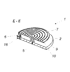
Figure 3a shows a cross-sectional view of the perfusion device 1
along the section line EE shown in Figure 2b. It can be seen that the
geometrical structure 7 which is in the form of a web has curved side flanks
10 so that the passage 8 is of a semicircular cross-section. It is further
possible to see the supply line 5 which connects the inlet opening 15 to the
perfusion region 2 and in that case opens into the spiral passage 8 as well
as the discharge line 6 which is arranged at the outer edge of the spiral
passage 8 and connects the outlet opening 16 to the perfusion region 2.
Figure 3b shows a cross-sectional view along section line CC in
Figure 2c. Once again it is possible to see the semicircular cross-section of
the passage 8 which is formed by curved side flanks 10 of the geometrical
structure 7 in the form of a web. It is possible to see the supply line 5
CA 03049060 2019-07-02
16
which is in the form of a tube connection and which connects the inlet
opening 15 to the perfusion region 2.
Alternatively the inlet opening 15 and the outlet opening 16 can also
be interchanged so that the fresh nutrient medium 4 is supplied at the
outer edge of the spiral passage 8.
Figures 4a to 4f show a further embodiment of the perfusion device
according to the invention, which substantially differs from the perfusion
device 1 of Figures 2a to 2d and 3a and 3b in that the cover plate 9 has a
holding element 12 with which the perfusion device 1 together with
perfusion region 2 can be inserted with one handhold into the cell culture
container 3.
The side views in Figures 4c and 4e show a seal 14 which is arranged
around the edge of the perfusion region 2 and serves for sealingly closing
off a circular cell culture container 3, for example a petri dish. Figure 4b
shows a plan view of this embodiment of the perfusion device 1 from
below, substantially corresponding to the view in Figure 2b. Figure 4b
shows a plan view from above, showing the holding element 12.
Figure 4f shows a cross-sectional view along section line CC in Figure
4b. It is possible to see the supply line 5 which in this embodiment is in
the form of a passage and the discharge line 6 which is in the form of a
passage and with which the inlet opening 15 and the outlet opening 16 are
connected to the perfusion region 2.
Figure 4g shows a sectional view along section line AA in Figure 4c,
in which it is possible to see once again the supply line 5 and the
semicircular cross-section of the passage 8 which is formed by the curved
side flanks 10 of the geometrical structure 7 in the form of the web.
The embodiment of the perfusion device 1 according to the invention
shown in Figures 5a to 5g differs from the embodiment shown in Figures 4a
to 4g substantially only in that both the inlet opening 15 and also the outlet
opening 16 are arranged on the top side of the cover plate 9 and not on the
side surface.
As shown by means of the cross-sectional view shown in Figure 5f
along section line CC in Figure 5b this arrangement of the inlet opening 15
CA 03049060 2019-07-02
17
and the outlet opening 16 involves the advantage that the supply line 5 and
the discharge line 6 can be less complicated and can be implemented with
shorter portions which in this embodiment are in passage form. That is
also shown in the cross-sectional view in Figure 5g showing a cross-section
taken along section line AA in Figure 5c. This view shows the supply line 5
which goes directly into the inlet opening 15. Both the inlet opening 15
and also the outlet opening 16 are arranged directly above the mouth
opening of the supply line 5 and the discharge line 6 connecting to the
perfusion region 2.
Figures 6a to 6h show a further embodiment of the perfusion device
1 according to the invention. Once again the perfusion device 1 has a
round cover plate 9 with a holding element 12 for easily inserting the
perfusion region 2, which is also round, in a cell culture container 3. The
perfusion region 2 is edged around by a seal 14 serving for sealingly closing
off the cell culture container 3.
In this embodiment the perfusion device 1 has a first inlet opening
15a arranged centrally in the cover plate 9. A second inlet opening 15b is
arranged at the edge of the cover plate 9. The first inlet opening 15a and
the second inlet opening 15b are connected to the perfusion region 2 by
.. way of a first supply line 5a and a second supply line 5b. The first supply
line 5a and the second supply line 5b are particularly clearly shown in the
cross-sectional view of Figure 6f illustrating a cross-section along section
line BB in Figure 6b. As the first inlet opening 15a and the second inlet
opening 15b are arranged directly above on the top side of the cover plate
.. 9 the first supply line 5a and the second supply line 5b can be kept short.
A first outlet opening 16a is arranged at the edge of the cover plate
while a second outlet opening 16b is arranged centrally in the proximity of
the first inlet opening 15a. The first outlet opening 16a and the second
outlet opening 16b are connected to the perfusion region 2 by way of a first
discharge line 6a and a second discharge line 6b. That can be clearly seen
in the cross-sectional view in Figure 6g illustrating a cross-section along
section line AA in Figure 6b. Once again the first discharge line 6a and the
second discharge line 6b can be kept short as the first outlet opening 16a
CA 03049060 2019-07-02
18
and the second outlet opening 16b are arranged directly above at the top
side of the cover plate 9.
As can be seen from the view from below in Figure 6b the first
supply line 5a opens into a first passage 8a into which the first discharge
line 6a also opens. The second supply line 5b like the second discharge line
6b opens into a second passage 8b. Both the first passage 8a and also the
second passage 8b are of a spiral-shaped configuration. The first passage
8a and the second passage 8b are formed by the intermediate spaces of a
spiral-shaped web representing the geometrical structure 7 of the perfusion
region 2.
In general the nutrient medium 4 and/or a test substance or
medicaments pass into the passage 8 at the supply line 2 and flow through
the passage in the direction of the discharge line 6 where the unused
nutrient medium 4 is discharged optionally jointly with excretion products
from the cells 11.
In the present case the nutrient medium 4 passes into the first
passage 8a at the first supply line 5a and flows through same in the
direction of the first discharge line 6a where it issues from the first
passage
8a. The nutrient medium 4 and/or a test substance or medicaments pass
into the second passage 8b at the second supply line 5b and flow through
same in the direction of the second discharge line 6b where the unused
nutrient medium issues from the perfusion region 2 optionally with
excretion products from the cells 11. As in this embodiment the first
supply line 5a is arranged centrally while the second supply line 5b is
arranged at the outer edge the nutrient medium 4 flows through the first
passage 8a and the second passage 8b in opposite relationship.
If for example along the passage 8a and 8b a total of 20 k of the
supplied nutrient medium 4 is used, that is to say 80% of the supplied
fresh nutrient medium 4 issues again at the outlet opening, it is then
possible by virtue of the oppositely directed flow to provide on average
around 900/0 of fresh nutrient medium 4 for the cells 11. Accordingly
extremely homogeneous environmental conditions obtain for the cells 11,
which has been found to be extremely advantageous for the investigations
CA 03049060 2019-07-02
19
into the behaviour of the cells 11, for example with the supply of certain
medicaments or test substances. The oppositely directed flow relationship
of the first spiral-shaped passage 8a and the second spiral-shaped passage
8b can be particularly clearly seen in Figure 6b.
Figure 6h shows a cross-sectional view along section line CC in
Figure 6c.
Figure 7a shows a plan view of a further embodiment of a perfusion
device 1 according to the invention with a geometrical structure 7 which is
in the form of a spiral-shaped web and the intermediate spaces of which
form an also spiral-shaped passage 8 through which the nutrient medium 4
can flow, the nutrient medium 4 entering at a supply line 5 which opens
into the passage 8 and issuing at a discharge line 6 which also connects to
the passage 8. Arranged on both sides of the web are devices 17 for flow
deflection in the form of chicanes which lead to microcirculation and better
circulatory flow of the nutrient medium 4 flowing therethrough.
Figure 7b shows a diagrammatic cross-sectional view showing the
arrangement of the flow deflection devices 17 arranged in the side flanks
10 of the web, with which the microcirculation of the nutrient medium 4
flowing therethrough is increased.
Figure 7c shows a cross-sectional view along section line EE in Figure
7a, also showing the flow deflection devices 17 which are arranged as
chicanes at the side flanks 10 of the geometrical structure 7 which is in the
form of a web.
Figure 8a shows a perspective view of a set according to the
invention including a cell culture container 3 which is in the form of a multi-
well plate and which has a plurality of chamber-shaped recesses 18 (shown
in broken line), on the bottom of which cell cultures 11 are arranged. The
perfusion device 1 can serve as a cover for the multi-well plate. The
perfusion device 1 has a plurality of perfusion regions 2, each perfusion
region 2 being inserted into one of the chamber-shaped recesses 18. In
addition the perfusion device 1 has a plurality of holding elements 12
respectively associated with a perfusion region 2. In addition an inlet
opening 15 and an outlet opening 16 is associated with each perfusion
CA 03049060 2019-07-02
region 2. The inlet opening 15 and the outlet opening 16 are connected to
the respective perfusion region 2 by way of a supply line 5 and a discharge
line 6 so that each individual chamber-shaped recess 18 can be supplied
with nutrient medium 4. As a respective inlet opening 15 and outlet
5 opening 16 are associated with each chamber-shaped recess 18 the
individual recesses 18 can be supplied with differing nutrient media so that
a plurality of different tests can be carried out at the same time.
Figure 8b shows a diagrammatic view of a set according to the
invention comprising a cell culture container 3 in the form of a petri dish
10 and a perfusion device 1, the perfusion region of which is inserted
into the
petri dish.