Note: Descriptions are shown in the official language in which they were submitted.
I
Device for audio signal processing for a piezoelectric speaker
The present invention relates to a device for audio signal processing for a pi-
ezoelectric speaker for generating sound waves in the audible wavelength
spectrum. The device comprises a signal input for a digital audio signal, a
digital correction unit for correcting a nonlinearity of the speaker, and a
digital
PWM generator by means of which the signal corrected by the correction unit
can be converted into a pulse-width modulated switch signal. The device fur-
ther comprises a power stage able to be actuated by means of the switch
signal converted by the PWM generator, such that a piezoelectric actuator of
the speaker can be charged with a voltage for deflecting a membrane. The
device further comprises a feedback implementing a closed-loop control cir-
cuit, by means of which the voltage can be fed back as a feedback signal,
wherein the feedback signal comprises a signal noise in the audible frequen-
cy range during normal operation caused by the correction unit, the PWM
generator, the power stage, and/or the piezoelectric speaker. The present
invention further relates to a method for audio signal processing for a piezoe-
lectric speaker for generating sound waves in the audible wavelength spec-
trum.
A device for operating a piezoelectric speaker is known from US
2010/0271147 Al. A disadvantage thereof is that a sound quality of the
speaker is not sufficient.
The object of the present invention is thus to improve the sound quality of
the
sound waves emitted by the piezoelectric speaker.
The object is achieved by a device for audio signal processing for a piezoe-
lectric speaker and an associated method having the features of the inde-
pendent claims.
CA 3049359 2019-07-11
2
The invention proposes a device for audio signal processing for a piezoelec-
tric speaker for generating sound waves in the audible wavelength spectrum.
The audible wavelength spectrum for humans ranges from approximately 20
Hz to 20 kHz, wherein said range can vary from person to person and can
particularly depend on the age of the person. Lower and higher frequencies
are not perceptible to the human ear.
The device comprises a signal input for a digital audio signal. The audio sig-
nal can comprise music, sounds, and/or speech, for example, originating
from a smartphone, an MP3 player, or another device. The audio signal is
therein fed into the device via the signal input in order to be output by the
pi-
ezoelectric speaker.
The device further comprises a digital correction unit for correcting a
nonline-
arity of the speaker. The digital correction unit can receive the digital
audio
signal from the signal input. The digital correction unit can thus be
connected
downstream of the signal input in the direction of signal flow. The nonlineari-
ties become evident in that a change in the digital audio signal is not
linearly
proportional to a change in the sound output by the piezoelectric speaker.
This can be substantially explained by the fact that the piezoelectric compris-
es a complex, nonlinear behavior. Temperature changes in the device and/or
the piezoelectric speaker can also lead to nonlinearities. By means of the dig-
ital correction unit, the nonlinearities can be reduced, so that a sound
quality
of the piezoelectric speaker can be improved.
The device further comprises a digital PWM generator by means of which the
signal corrected by the correction unit can be converted into a pulse-width
modulated switch signal. The digital PWM generator can thus be connected
downstream of the digital correction unit in the direction of signal flow.
The device further comprises a power stage able to be actuated by means of
the switch signal converted by the PWM generator, such that a piezoelectric
CA 3049359 2019-07-11
3
actuator of the speaker can be charged with a voltage for deflecting a mem-
brane. The power stage can be connected downstream of the PWM genera-
tor in the direction of signal flow. The power stage can comprise an amplifier
unit able to charging and discharging the piezoelectric actuator of the speak-
er with a voltage. The power stage can provide an output signal so that the
speaker can output a sound corresponding to the digital audio signal, possi-
bly comprising music, sound, and/or tones. The power stage can also com-
prise at least one switch for processing the switch signal of the PWM genera-
tor.
The piezoelectric speaker can be at least partially charged with electrical en-
ergy from an energy unit by the power stage and then at least partially dis-
charged, thereby generating sound waves. The electrical energy can therein
be provided by the energy unit. The piezoelectric speaker comprises piezoe-
lectric properties, that is, the piezoelectric speaker can be deflected as a
function of the charge state thereof. The greater the charge of the piezoelec-
tric speaker with electrical energy, the greater the deflection of the
piezoelec-
tric speaker. The sound waves can be generated by means of the deflection
of the piezoelectric speaker if the deflection is transmitted to the membrane,
for example. The air disposed above the membrane can thereby be set to
vibrating so that the sound waves are generated. The deflection of the piezo-
electric speaker can further be modified in that said actuator is charged and
discharged. If the piezoelectric speaker is charged further, the deflection
can
be increased. In order to reduce the deflection, in contrast, the
piezoelectric
speaker can be discharged. The piezoelectric speaker can thus be set to vi-
brating by alternately charging and discharging, wherein the vibrations are
transmitted to the membrane, for example, such that the sound waves are
generated. The piezoelectric speaker can therein be incrementally charged
and discharged.
Sound waves can thus be generated by the controlled deflection of the pie-
zoelectric speaker. If the deflection occurs according to the digital audio
sig-
CA 3049359 2019-07-11
4
nal, for example comprising tones, sounds, or music, a corresponding noise,
also comprising tones, sounds, or music, is generated by means of the pie-
zoelectric speaker. The audio signal can be present in the form of a music
file, for example. The audio signal can also be provided by a conversational
partner on a phone call, for example.
By charging and discharging with electrical energy, an electrical voltage at
the piezoelectric speaker also rises and falls. As the voltage at the
piezoelec-
tric speaker increases, the deflection rises. The deflection further falls as
the
voltage at the piezoelectric speaker drops. The piezoelectric speaker further
has a capacitance, as an electrical field is established by the charging of
the
piezoelectric speaker with electrical energy as a function of the electrical
voltage. The piezoelectric speaker can thus comprise properties of a capaci-
tor. The charge state and the electrical voltage of the piezoelectric speaker
and the displacement can also be interdependent.
The power stage can be a voltage transformer, for example. By means of the
power stage, the piezoelectric actuator can be charged to 30V, for example,
even if only 3V is made available by an energy source, such as a battery.
The power stage can therein charge the piezoelectric actuator Incrementally
or in cycles. The charging of the piezoelectric actuator therein depends on
the digital audio signal.
In addition or alternatively, the power stage can also discharge the piezoelec-
tric actuator. This can be performed if the deflection of the membrane is to
be
reduced. A lesser deflection of the piezoelectric actuator therein corresponds
to a lesser deflection of the membrane. The electrical energy released by
discharging can therein be stored in the energy source again.
The device further comprises a feedback implementing a closed-loop control
circuit, by means of which the voltage of the piezoelectric actuator can be
fed
back as a feedback signal, wherein the feedback signal comprises a signal
CA 3049359 2019-07-11
5
noise in the audible frequency range during normal operation caused by the
correction unit, the PWM generator, the power stage, and/or the piezoelectric
speaker. The feedback thus closes the closed-loop control circuit, so that the
sound quality of the speaker can be improved. The feedback can feed back
the feedback signal upstream of the digital correction unit, particularly in
the
direction of signal flow.
The first signal noise leads to reduced sound quality of the piezoelectric
speaker. The first signal noise can be caused, for example, in that the
digital
audio signal is converted into an analog voltage for the piezoelectric
actuator
from the signal input, through the correction unit, through the PWM genera-
tor, through the power stage, and to the piezoelectric actuator. This can only
be performed with finite precision, however, as the PWM generator for ex-
ample can convert the signal corrected by the correction unit into the switch
signal with some imprecision. The PWM generator can comprise quantization
noise, for example. In addition or alternatively, the correction unit, the
power
stage, and/or the piezoelectric speaker can comprise the quantization noise.
The precision of the correction unit, the PWM generator, and/or the power
stage can be only 8 bits, for example, leading to the device being compact in
design. Such a resolution, however, can lead to said quantization errors and
to quantization noise. In addition, the remaining nonlinearity also reduces
the
quality of the audio signal and/or of the sound generated by the speaker.
According to the invention, the device comprises a noise shaping unit de-
signed and/or implemented in the closed-loop control circuit such that a noise
energy of the first signal noise of the correction unit, the PWM generator,
the
power stage, and/or the piezoelectric speaker can be shifted outside of the
audible frequency range by means of said unit. Outside of the audible fre-
quency range, humans can no longer perceive the first signal noise, so that
the sound quality of the speaker is improved.
CA 3049359 2019-07-11
6
It is advantageous if the noise energy of the first signal noise can be
shifted
into a high-frequency range by means of the noise shaping unit. The high-
frequency range can be above 20 kHz, for example, wherein humans can no
longer perceive the first signal noise. In addition or alternatively, the
noise
shaping unit can also shift the noise energy of the first signal noise into
the
range of a system sampling frequency of the device. The system sampling
frequency can be in the range of 1 MHz, for example. The system sampling
frequency can therein be the working frequency of the device. That is, the
system sampling frequency can be the frequency at which the device works,
particularly at which cycle time the device processes the audio signal.
The sound quality can thereby be improved. If the noise energy is shifted into
a high-frequency range, the piezoelectric actuator itself also attenuates such
frequencies. As the piezoelectric actuator comprises a certain mass, said ac-
tuator has a corresponding inertia. The piezoelectric actuator can no longer
track higher frequencies, so said high frequencies are damped by the piezoe-
lectric actuator itself. The piezoelectric actuator can act as a low-pass
filter
itself.
It is advantageous if the device is implemented as a closed-loop control cir-
cuit. The closed-loop control circuit can be computer-implemented. The
closed-loop control circuit can then be implemented by a computer program.
In addition or alternatively, the closed-loop control circuit can also be an
elec-
tronic closed-loop control circuit, so that the closed-loop control circuit is
dis-
posed in an ASIC, for example.
In addition or alternatively, the closed-loop control circuit can also
comprise a
forward path. The forward path can comprise the signal input, the digital cor-
rection unit, the PWM generator, the power stage, and/or the piezoelectric
speaker, for example. Said items can be disposed in the direction of signal
flow indicated here.
CA 3049359 2019-07-11
7
In addition or alternatively, the closed-loop control circuit can also
comprise
at least one feedback path. The feedback path can feed back the feedback
signal, potentially comprising the voltage of the piezoelectric actuator, so
that
the closed-loop control circuit is closed.
It is advantageous if the noise shaping unit is connected upstream of the cor-
rection unit in the direction of signal flow. The correction unit thereby
receives
the signal shaped by the noise shaping unit, in which the noise energy is
shifted outside of the audible wavelength spectrum. The noise shaping unit
can therein be connected upstream of the correction unit in the direction of
signal flow in the forward path, for example.
It is advantageous if the noise shaping unit comprises a noise shaping block
for shifting the noise energy of the first signal noise. The noise shaping
block
can be optimized for shifting the noise energy of the first signal noise
outside
of the audible wavelength spectrum.
In addition or alternatively, the noise shaping unit can comprise a loop
filter
for suppressing the quantization noise and/or a remaining nonlinearity after
the correction unit and/or the PWM generator and thus improving the quality
of the sound.
It is advantageous if the loop filter is connected upstream of the noise shap-
ing block in the direction of signal flow. In addition or alternatively, the
loop
filter can be connected upstream of the correction unit in the direction of
sig-
nal flow.
It is advantageous if the device comprises an analog/digital converter by
means of which the feedback signal can be digitalized, wherein the converted
digital feedback signal comprises a second signal noise caused by the ana-
log/digital converter during normal operation. The analog/digital converter is
also abbreviated as an AID converter, wherein here as well this abbreviation
CA 3049359 2019-07-11
8
is used. The feedback signal can be digitalized by means of the AID convert-
er, so that said signal can be processed in an electronic and/or logical
circuit.
As every AID converter has a finite resolution, errors also occur during digi-
talization, particularly quantization errors or quantization noise. The ND con-
verter thus generates the second signal noise.
It is advantageous if the AID converter is disposed in the feedback path. The
ND converter is connected downstream of the piezoelectric speaker in the
direction of signal flow.
It is advantageous if the noise shaping block is implemented so as to process
only the first signal noise. The noise shaping block thus does not process the
second signal noise. For example, the first signal noise can be greater than
the second signal noise, so that it is more effective to process only the
first
signal noise. The second signal noise can also be reduced and thus neglect-
ed if the AID converter has sufficiently high resolution. The AID converter
can
have a resolution of 12, 14, or 16 bits, for example.
It is advantageous if the noise shaping unit comprises a signal transfer func-
tion by means of which an actuating variable for actuating the speaker can be
determined using a control deviation between the digital audio signal and the
digital feedback signal. The actuating variable can be a voltage for actuating
the speaker. The actuating variable can also be a voltage differential by
means of which the piezoelectric speaker is charged or discharged. The con-
trol deviation indicates the deviation between an actual value of the voltage
of the piezoelectric actuator, namely the digital feedback signal, and the
specified value of the piezoelectric actuator depending on the digital audio
signal. If the control deviation is zero, then the piezoelectric actuator has
the
voltage that said actuator should have according to the digital audio signal.
The piezoelectric actuator thus emits the audio signal without error. The pie-
zoelectric actuator, however, comprises the first and/or second signal noise.
The first signal noise particularly leads to an error able to be determined by
CA 3049359 2019-07-11
9
the control deviation. The control deviation can be formed as the difference
between the digital audio signal and the digital feedback signal, for example.
The actuating variable for actuating the speaker can be determined therefrom
by means of the signal transfer function, so that the error is avoided. The ac-
tuating variable can be a voltage. The control deviation is therein the input
signal and the actuating variable is the output signal.
It is advantageous if the signal transfer function is implemented such that
the
control deviation can be delayed by one period by means of such function.
The period can advantageously be a period of the system sampling frequen-
cy or of the working frequency of the device. The control thereby affects the
next subsequent period, for example the feedback of the feedback signal.
It is advantageous if the signal transfer function STFd is defined by the
follow-
ing first formula:
X
ST F H (z)
d = d = [1 + 1 (z) * (1 + K (z))H (z)]
wherein H(z) is the system function, 1(z) is the speaker function, K(z) is the
inverse function of 1(z), d is the control deviation, and X is the actuating
van-
able for the speaker. The signal transfer function is defined by d as the
input
variable or signal and X as the output variable or signal. For a system func-
tion H(z), the signal transfer function STFd can be z1 For other system func-
tions H(z) the transfer function STFd can be different depending to the needs.
The signal transfer function STFd, for example, can also have higher orders.
It is advantageous if the noise shaping unit comprises a noise shaping trans-
fer function by means of which the noise energy of the first signal noise can
be shifted. The noise shaping transfer function can therein be implemented
so as to shift the noise energy of the first signal noise into the inaudible
CA 3049359 2019-07-11
10
wavelength spectrum, particularly to frequencies above 20 kHz, preferably
into a range of the system sampling frequency.
It is advantageous if the noise shaping transfer function is implemented such
that low frequencies are damped by means thereof. Said frequency range
comprising the noise energy is particularly damped, so that the sound quality
is improved.
It is advantageous if the noise shaping transfer function NTFd is defined by
the following second formula:
X 1
NTFd ¨ ¨
Qz [1 + 1(z) * (1+ K(z))H(z)]
wherein H(z) is the system function, 1(z) is the speaker function, K(z) is the
inverse function of 1(z), d is the control deviation, and X is the actuating
van-
able for the speaker. Q(z) can be the disturbance variable of the digital cor-
rection unit, of the PWM generator, of the power stage, and/or of the piezoe-
lectric speaker. Q(z) therein describes, for example, the quantization error
arising from the PWM generator. The first signal noise can be defined by
means of Q(z), for example. Q(z) can comprise all errors, for example, occur-
ring in the processing of the digital audio signal up to actuation, for
example
an output signal of the piezoelectric actuator. Q(z) can comprise the first
sig-
nal noise. Q(z) corresponds to the input signal and X to the output signal in
the noise shaping transfer function. For a system function H(z) the noise
shaping transfer function NTFd can be 1 - z-1. For other system functions H(z)
the noise shaping transfer function NTFd can be different depending to the
needs. The signal transfer function NTFd, for example, can also have higher
orders.
It is advantageous if the actuating variable transfer function is defined by
the
following third formula:
CA 3049359 2019-07-11
11
X(z) = d * STFd + Qz * NTFd
Said third formula comprises the signal transfer function as STFd and the
noise shaping transfer function as NTFd. The control deviation corresponds
to d and Q(z) to the first signal noise or the quantization error. For a
system
function H(z) X(z) can be z1 *d + Q,*(1 - z-1). For other system function H(z)
X(z) can be different depending to the needs.
It is advantageous if a controlled variable transfer function is defined by
the
following fourth formula:
STFd * 1(z) NTFd * 1(z)
Y(Z) = Vin _____________________________
(1+ STFd*1(z))+ Qz (1 + NTFd * 1(z))
wherein \An is the digital audio signal. For a system function H(z) Y(z) can
be
Z1 Vin + Qz*(1 - z-1). For other system function H(z) Y(z) can be different de-
pending to the needs.
It is advantageous if the noise shaping unit is implemented such that zeroes,
poles, and/or the order of at least one transfer function can be determined
thereby such that a signal-to-noise ratio is increased. In addition or alterna-
tively, the noise shaping unit is implemented such that zeroes, poles, and/or
the order of at least one transfer function can be determined therein such
harmonic distortion is decreased. The sound quality is thereby improved.
It is advantageous if the device comprises a control unit in which the signal
transfer function, the noise shaping transfer function, the actuating variable
transfer function, and/or the controlled variable transfer function are imple-
mented. The device can also comprise a microcontroller in which the signal
transfer function, the noise shaping transfer function, the actuating variable
CA 3049359 2019-07-11
12
transfer function, and/or the controlled variable transfer function are imple-
mented.
It is advantageous if measurement data for a standardized piezoelectric
speaker reflecting the nonlinear behavior thereof is saved in the digital cor-
rection unit. The measurement data can be saved in a table, for example.
The measurement data can further comprise the capacitance of the piezoe-
lectric speaker, for example, preferably saved as a function of the charge of
the piezoelectric speaker. The measurement data can therein comprise data
characterizing the behavior of the piezoelectric speaker. The measurement
data can, however, also comprise values for the correction unit, for the PWM
generator, and/or for the power stage. The measurement data can comprise
values, for example, for capacitances, inductivities, and/or characteristic
curves. It can therein be determined, for example, how long the piezoelectric
speaker or piezoelectric actuator must be charged in order to obtain a partic-
ular deflection of the membrane of the piezoelectric speaker corresponding to
an audio signal. The measurement data can comprise system parameters of
the device.
It is further advantageous if at least part of the nonlinearity of the speaker
can
be corrected under consideration of said measurement data. The sound qual-
ity of the piezoelectric speaker is thereby improved.
The invention further proposes a method for audio signal processing for a pi-
ezoelectric speaker for generating sound waves in the audible wavelength
spectrum. The device implemented according to one or more features of the
preceding and/or following description can therein be operated by means of
the method.
According to the method, a digital audio signal fed in via a signal input is
pro-
cessed. The sound is generated by the speaker by means of the digital audio
signal. The digital audio signal comprises information about music, tones,
CA 3049359 2019-07-11
13
and/or speech to be reproduced by the speaker. The method processes the
digital audio signal so that the speaker can convert the information stored in
the audio signal about the music, the tones, and/or the speech into the corre-
sponding sound.
According to the method, a nonlinearity of the speaker is corrected by a digi-
tal correction unit. As the speaker cannot react linearly to the audio signal,
the nonlinearities are corrected by means of the correction unit. Said nonlin-
earities can be cause, for example, as the speaker reacts differently to
differ-
ent conditions. For example, the piezoelectric speaker has a capacitance de-
pending on the momentary charge state of the piezoelectric speaker. The
correction unit can incorporate in the calculation the momentary state, for ex-
ample the charge state, of the piezoelectric speaker in order to correct the
nonlinearities. The temperature of the piezoelectric speaker can also lead to
nonlinearities. Different temperatures can lead to different behavior. The age
of the piezoelectric speaker can also lead to nonlinearities. An older speaker
can react differently to a signal than a newer speaker.
The signal corrected by the correction unit is further converted into a pulse-
width modulated switch signal by a digital PWM generator.
A power stage is actuated by means of the switch signal converted by the
PWM generator, such that a piezoelectric actuator of the speaker is charged
with a voltage for deflecting a membrane. When the membrane is deflected,
the air disposed above the membrane is induced to vibrate, corresponding to
sound waves transmitting the tones, the music, and/or the speech. As a re-
sult, deflecting the membrane correctly is important. Incorrectly deflecting
the
membrane causes sound waves transmitting distorted or erroneous speech,
tones, and/or speech. In order to achieve a high sound quality, it is advanta-
geous that the deflection correspond as well as possible to the digital audio
signal.
CA 3049359 2019-07-11
14
The membrane can therein be deflected incrementally when the piezoelectric
actuator is charged incrementally. This can be performed, for example, if an
energy source, such as a battery, comprises a supply voltage of 3 V, but the
piezoelectric actuator is charged at up to 30 V.
The power stage can comprise at least one switch, for example, actuated by
the pulse-width modulated switch signal of the PWM generator. The piezoe-
lectric actuator is thereby charged with a voltage potentially having an
analog
value. The correction unit, the PWM generator, and/or the power stage can
thus convert the digital audio signal into a voltage of the piezoelectric
actua-
tor, wherein the voltage has an analog value. The correction unit, the PWM
generator, and/or the power stage can thus act as a digital/analog converter.
The voltage of the piezoelectric actuator is further fed back as a feedback
signal via a feedback of a closed-loop control circuit. The feedback signal
therein comprises a first signal noise in the audible frequency range during
normal operation caused by the correction unit, the PWM generator, the
power stage, and/or the piezoelectric speaker. The feedback thus closes the
closed-loop control circuit. The sound quality of the piezoelectric speaker is
improved by means of the closed-loop control circuit. For example, errors in
the output sound arising from errors in the signal processing of the
correction
unit, of the PWM generator, of the piezoelectric speaker, and/or of the power
stage can be minimized by means of the closed-loop control circuit.
According to the invention, a noise energy of the first signal noise of the
cor-
rection unit, of the PWM generator, of the power stage, and/or of the piezoe-
lectric speaker is shifted out of the audible frequency range by means of the
noise shaping unit. The noise energy can therein be shifted into a range
above the audible frequency range. For example, the noise energy can be
shifted above a frequency of 20 kHz. In such a frequency range, the human
ear can no longer perceive the first signal noise, so that the sound quality
of
the sound output by the speaker is improved. Alternatively, the noise energy
CA 3049359 2019-07-11
15
can also be shifted into range of the system sampling frequency. The system
sampling frequency can also be the working frequency of the method for au-
dio signal processing and lie in a range of 1 MHz, for example. In such a fre-
quency range, the piezoelectric actuator or speaker has an inertia, so that
the
piezoelectric actuator or speaker can no longer follow said frequency. The
noise energy of the first signal noise is thereby damped. The piezoelectric
actuator or speaker have properties of a low-pass filter.
Further advantages of the invention are described in the embodiment exam-
ples below. In the drawings:
Figure 1 A block circuit diagram of a device for audio signal
processing
for a piezoelectric speaker,
Figure 2 A block circuit diagram of a device for audio signal processing
for a piezoelectric speaker having a noise shaping unit, and
Figure 3 A flow chart of the linear model for signal processing for
a pie-
zoelectric speaker.
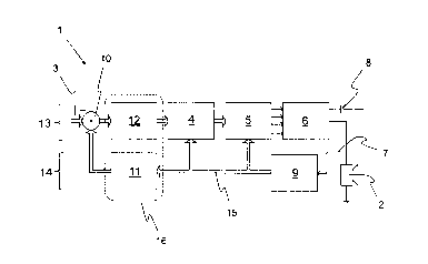
Figure 1 shows a block circuit diagram of a device 1 for audio signal pro-
cessing for a piezoelectric speaker 2. Sound waves in the audible wave-
length spectrum can be produced by means of the piezoelectric speaker 2
and can be perceived by the human ear. The sound waves can comprise
tones, music, and/or speech, so that music can be listened to or telephone
calls made by means of the speaker 2, for example. The device 1 and the
speaker 2 can thus be disposed in a smartphone, in an MP3 player, or in an-
other, particularly portable, device.
The piezoelectric speaker 2 comprises a piezoelectric actuator not shown
here, by means of which a membrane, also not shown here, of the speaker 2
can be deflected in order to induce vibrations in air above the membrane, so
CA 3049359 2019-07-11
16
that the sound waves are generated for transporting the tones, the music,
and/or the speech.
In order to deflect the piezoelectric actuator, said actuator can be charged
with an electrical voltage. When the electrical voltage of the piezoelectric
ac-
tuator rises and falls, the deflection thereof also increases and decreases.
By
charging the piezoelectric actuator, electrical energy can be stored therein,
so that the actuator comprises properties of a capacitor and has a capaci-
tance.
The device 1 further comprises a signal input 3 for a digital audio signal.
The
digital audio signal comprises acoustic information corresponding to the mu-
sic, the tones, and/or the speech to be generated by the speaker 2. In gen-
eral, the audio signal comprises information about the sound waves to be
generated by the speaker 2. A quality of the sound waves generated by the
speaker 2, particularly a sound quality, can depend on the device 1 deflecting
the piezoelectric actuator to match the digital audio signal.
The device 1 according to the present embodiment example comprises a dig-
ital correction unit 4 by means of which the nonlinearity of the piezoelectric
speaker 2 can be corrected. Nonlinearities can occur, for example, because
a change in the deflection of the piezoelectric actuator depends on the mo-
mentary deflection of the piezoelectric actuator itself. The capacitance of
the
piezoelectric actuator can also depend on the deflection and is thus also a
source of nonlinearity. When determining the voltage with which the piezoe-
lectric actuator is charged, for example, the momentary voltage must also be
considered. The nonlinearities can therein have a plurality of causes. A size,
the temperature, or an age of the piezoelectric actuator can also be consid-
ered. In addition or alternatively, however, the device 1 itself can also lead
to
nonlinearities of the speaker 2.
CA 3049359 2019-07-11
17
The digital correction unit 4 can receive the digital audio signal and output
a
corrected signal.
The device 1 further comprises a digital PWM generator 5 by means of which
the signal corrected by the correction unit 4 can be converted into a pulse-
width modulated switch signal.
The device 1 further comprises a power stage 6 for actuating by means of
the switch signal converted by the PWM generator 5, such that the piezoelec-
tric actuator of the piezoelectric speaker 2 for deflecting the membrane can
be charged with a voltage. The power stage 6 can be an amplifier unit, for
example, which rises the voltage from 3V up to 30V. The power stage 6 can
process the pulse-width modulated switch signal, such that the piezoelectric
actuator of the speaker 2 is charged with the voltage. The voltage with which
the piezoelectric actuator is charged therein depends on the pulse-width
modulated switch signal. The voltage of the actuator can be adjusted by
means of the pulse-width modulated switch signal. The voltage is therein ad-
justed such that the piezoelectric actuator is charged such that the mem-
brane is deflected such that a sound matching the digital audio signal is pro-
duced.
The power stage 6 can thereby be supplied with electrical energy by a power
supply 8 in order to charge the piezoelectric actuator or piezoelectric
speaker
2. The power supply 8 can be a battery of a smartphone, for example.
In order to implement a closed-loop control circuit, the device 1 comprises a
feedback 7 by means of which the voltage of the piezoelectric actuator can
be fed back as a feedback signal.
The feedback 7 can be fed back to a first summing point 10. The first sum-
ming point 10 can be implemented such that said point compares the feed-
back signal to the digital audio signal. The first summing point 10 can form a
CA 3049359 2019-07-11
18
difference between the feedback signal and the digital audio signal, for ex-
ample. As the first summing point 10 forms a difference, said point can also
be a subtraction point. An error or deviation between the audio signal and the
voltage at the piezoelectric actuator can thereby be determined, correspond-
ing to a deviation between the specified value, representing the digital audio
signal, and the momentary value, representing the voltage at the piezoelec-
tric actuator.
Before the feedback signal is fed back to the first summing point 10, said sig-
nal can be fed back to an analog/digital converter 9 (or ND converter for
short). The feedback signal can be digitalized by the ND converter 9 in order
to be able to process said signal in an electronic or logical circuit.
The feedback signal comprises a first signal noise in the audible frequency
range of the sound waves produced by the piezoelectric speaker 2 during
normal operation, caused by the correction unit 4, the PWM generator 5, the
power stage 6, and/or the piezoelectric speaker 2.
The first signal noise can arise from a quantization noise or quantization er-
ror, for example. The correction unit 4, the PWM generator 5, the power
stage 6, and/or the piezoelectric speaker 2 can describe the digital/analog
converter (or D/A converter for short), as said items convert a digital audio
signal at the signal input 3 into a voltage of the piezoelectric actuator,
where-
in said voltage is analog. The correction unit 4, the PWM generator 5, and
the power stage 6 can be summarized as a D/A converter, as said items
convert a digital audio signal into an output signal for the piezoelectric
speaker 2. Converting from the digital audio signal into the voltage of the ac-
tuator or the output signal for the speaker 2, the quantization errors can oc-
cur, leading to the first signal noise and potentially leading to a reduced
sound quality in the audible frequency range.
CA 3049359 2019-07-11
19
The device 1 further comprises a forward path 13. The forward path 13 in the
present embodiment comprises the signal input 3, the digital correction unit
4, the PWM generator 5, and the power stage 6. In addition, the forward path
13 also comprises the piezoelectric speaker 2, although said speaker is not
disposed in a line with the other elements of the forward path 13 in Figure 1.
The power supply 8 can also be part of the forward path 13.
The device 1 additionally or alternatively comprises a feedback path 14. The
feedback path 14 here comprises the ND converter 9 for receiving, digitaliz-
ing, and feeding back the feedback signal from the piezoelectric speaker 2.
The forward path 13 and the feedback path 14 can form the closed-loop con-
trol circuit.
The device 1 or the closed-loop control circuit further comprises a signal
flow
15, wherein the direction of signal flow is marked in the figures by the
arrows.
The signal flow 15 runs, for example, from the signal input 3 through the
first
summing point 10, through the correction unit 4, through the PWM generator
5, through the power stage 6, to the piezoelectric speaker 2, wherein said
flow can form the forward path 13. The signal flow 15 further runs from the
piezoelectric speaker 2 through the ND converter 9, back to the signal input
3 or the first summing point 10, wherein said flow can form the feedback
path. The signal flow 15 is thus run in a closed-loop control circuit.
Figure 2 shows a block circuit diagram of a device 1 for audio signal pro-
cessing for the piezoelectric speaker 2. The device 1 comprises a noise
shaping unit 16 implemented such that the noise shaping of the first signal
noise of the correction unit 4, of the PWM generator 5, of the power stage 6,
and/or of the piezoelectric speaker 2 can be shifted outside of the audible
frequency range by means thereof. For example, the noise energy of the first
signal noise can be shifted into a range above the audible frequency range.
The audible frequency range ends at about 20 kHz, so that the noise energy
CA 3049359 2019-07-11
20
of the first signal noise, when shifted there, can no longer be perceived by
the human ear. For example, the noise energy can be shifted into a frequen-
cy range higher than 20 kHz or higher than 100 kHz.
The noise energy of the first signal noise can therein also be shifted into a
frequency range of a system sampling frequency of the device 1. The system
sampling frequency can be the working frequency of the device 1, for exam-
ple. Said frequency can be in the range of 1 MHz, for example. At such high
frequencies, the noise energy of the first signal noise can also be damped, as
the piezoelectric actuator cannot follow such high frequencies. The piezoe-
lectric actuator can therefore comprise properties of a low-pass filter.
The noise shaping unit 16 can be connected upstream of the correction unit 4
in the direction of the signal flow 15 according to the present embodiment
example. For example, the noise shaping unit 16 can be disposed in the for-
ward path 13 and/or in the feedback path 14. The noise shaping unit 16 is
further connected downstream of the AID converter 9 in the direction of the
signal flow 15.
The noise shaping unit 16 can further comprise a noise shaping block 11
and/or a, particularly digital, loop filter 12, according to the present
embodi-
ment example. The noise energy of the first signal noise can be shifted out-
side the audible frequency range by means of the noise shaping block 11.
The noise shaping block 11 is disposed here in the feedback path 14. The
noise shaping block 11 is further connected downstream of the AID converter
9 in the direction of the signal flow 15. The noise shaping block 11 is
further
connected upstream of the signal input 3 in the direction of the signal flow
15.
The noise shaping block 11 thus shifts the noise energy outside of the audi-
ble frequency range in one method. The signal shaped by the noise shaping
block 11 and/or the noise shaping unit 16 is then fed to the first summing
point 10 according to the method.
CA 3049359 2019-07-11
21
The loop filter 12 is disposed in the forward path 13. The loop filter 12 is
fur-
ther connected downstream of the signal input 3 in the direction of the signal
flow 15. The loop filter 12 is connected upstream of the correction unit 4 in
the direction of the signal flow 15.
Figure 3 shows a flow chart for audio signal processing for the piezoelectric
speaker 2.
The digital audio signal Vin can be fed into the signal input 3. The first sum-
ming point 10 follows downstream of the signal input 3 in the direction of the
signal flow 15. The digital audio signal Vin can be compared with a digital
feedback signal Yd,g at the first summing point 10. For example, a difference
can be formed from the two signals. For example, d = Vin - Yd,g can be
formed. The digital feedback signal Yd,g of a previous system cycle of the de-
vice 1 can therein advantageously be compared with the momentary digital
audio signal V. For example, d = Vin (n)- Ydig (n-1) can be determined. The
control deviation can thus be d. The value d is also the amount by which the
voltage of the piezoelectric speaker 2 must be adjusted. This can be zero, if
a
voltage is present at the piezoelectric actuator of the speaker 2 and should
be present in order to generate the corresponding sound according to the
digital audio signal V,n. Due to errors, however, such as due to the
nonlineari-
ties of the piezoelectric speaker 2, the first signal noise Qz, and/or a
second
signal noise ed, a control deviation d unequal to zero can occur.
The control deviation d is fed to a second summing point 17 in the direction
of the signal flow 15. The control deviation d can be compared with a voltage
change dy of the piezoelectric speaker 2 in the second summing point 17. A
difference dy in successive voltages of the piezoelectric speaker 2 can be
defined. For example, the second summing point 17 can form a difference
between the control deviation d and the change in voltage dy. For example, P
= d - dy can be formed according to the present example.
CA 3049359 2019-07-11
22
The input signal P can be fed into the noise shaping unit 16 in the direction
of
the signal flow 15. The noise shaping unit 16 can comprise a system function
H(z). The noise shaping unit can further comprise a signal transfer function
STFd defined according to a first formula:
X
ST F H (z)
d - ¨ _______________________________________________
d [1 + 1(z) * (1 + K
(z))1I (z)]
The signal transfer function STFd can describe the behavior as the control
deviation d changes to an actuating variable X, preferably for a linear
system.
In the formula or formulas, H(z) is the system function, 1(z) is the speaker
function, K(z) is the inverse function of 1(z), d is the control deviation,
and X is
the actuating variable for the speaker. X can thus be the voltage by means of
which the speaker 2 is charge and can be analog.
The control deviation d can further be shifted by a period of the system sam-
pling frequency or the working frequency by means of the signal transfer
function STFd. The control deviation d can thereby be delayed by one period.
Different H(z) can produce different STFd.
A digital/analog converter Q is disposed in the direction of the signal flow
15
for the noise shaping unit 16 and can comprise the digital correction unit 4,
the PVVM converter 5, and the power stage 6. The input signal R can be pro-
vided to the digital/analog converter Q. The input signal R can be defined as
R = (d ¨ dy)H(z) = P*H(z). The digital/analog converter Q further comprises
the disturbance variable Qz, leading schematically into the digital/analog con-
verter Q in Figure 3. The disturbance variable Q, corresponds here to the
first
signal noise Qz potentially implemented by the correction unit 4, the PWM
generator 5, the power stage 6, and/or the piezoelectric speaker 2.
The processing of the first signal noise Qz can be described by means of a
noise shaping transfer function NTFd, wherein said processing can be im-
CA 3049359 2019-07-11
23
plemented by the noise shaping unit 16. The noise shaping transfer function
NTFd can therein be defined according to a second formula as follows:
X 1
NTFd = ¨ = ____________________________________________
Qz [1+ 1(z)* (1+
K(z))11(z)]
An actuating variable transfer function X(z) can further be defined according
to a third formula for a particular selection of H(z)
X(z) = d * STFd + Qz * NTFd = z-1 * d + Qz * (1¨ z-1)
The signal transfer function therein is STFd and the noise shaping transfer
function is NTFd. X(z) depends on the choice of the system function H(z).
Y(z) is defined according to the following fourth formula for a particular
selec-
tion of H(z):
STFd * 1(z) NTFd * 1(z)
Y(Z) = Ili,
(1+ STFa *1(z))+ Qz (1+ NTFd * 1(z)) =
According to the said fourth formula, the noise energy of the first signal
noise
Q, can be damped in the audio band. The noise energy of the first signal
noise Qz can be shifted into a high frequency range, wherein the human ear
can no longer perceive the noise energy of the first signal noise Q, and there-
fore the sound quality is improved. Y(z) depends on the choice of the system
function H(z).
The controlled variable Y(z) in the form of the voltage of the piezoelectric
speaker 2 can be digitalized by means of the AID converter 9. A quantization
error or a quantization noise can occur due to the digitalization and is
present
in the second signal noise ed. If the resolution of the AID converter 9 is se-
lected to be high enough, for example 12 bits, 14 bits, or 16 bits, then the
CA 3049359 2019-07-11
24
second signal noise ed can be negligible. Only the first signal noise Q, can,
for example, be shifted out of the audible frequency range by means of the
noise shaping unit 16.
The present invention is not limited to the exemplary embodiments shown
and described. Modifications in the context of the patent claims are also pos-
sible, as is a combination of features, even if these are shown and described
in different exemplary embodiments.
CA 3049359 2019-07-11
25
Reference list
1 Device for audio signal processing
2 Piezoelectric speaker
3 Signal input
4 Digital correction unit
5 Digital PWM generator
6 Power stage
7 Feedback
8 Power supply
9 Analog/digital converter
10 First summing point
11 Noise shaping block
12 Loop filter
13 Forward path
14 Feedback path
15 Signal flow
16 Noise shaping unit
17 Second summing point
Val Digital audio signal
d Control deviation
dy Voltage change at piezoelectric speaker
P Noise shaping unit input signal
R Digital/analog converter input signal
Qz First signal noise
Q Digital/analog converter
X Actuating variable
1(z) Speaker function
Y(z) Controlled variable
H(z) System function
CA 3049359 2019-07-11
26
K(z) Inverse function of 1(z)
ed Second signal noise
Yclig Digital feedback signal
STFd Signal transfer function
NTFd Noise shaping transfer function
CA 3049359 2019-07-11