Note: Descriptions are shown in the official language in which they were submitted.
CA 03049549 2019-07-05
WO 2018/136640
PCT/US2018/014245
PUMPING/NURSING GARMENT
Cross-reference to Related Applications
[0001] This application claims priority to U.S. Provisional Patent Application
No.
62/448,622, filed January 20, 2017 and U.S. Provisional Patent Application No.
62/548,706,
filed August 22, 2017, each of the disclosures of which is incorporated by
reference in its
entirety.
[0002] This application is related to International Application No.
PCT/U516/43326, filed
July 21, 2016, which claims priority to U.S. Provisional Application No.
62/196,080, filed
July 23, 2015; and is related to U.S. Non-Provisional Application No.
14/172,826, entitled
"Pumping/Nursing Bra", filed February 4, 2014, which claims priority to U.S.
Provisional
Application No. 61/832,592, filed on June 7, 2013; and is related to U.S. Non-
Provisional
Application No. 14/172,812, entitled "Pumping/Nursing Bra", filed February 4,
2014, which
also claims priority to U.S. Provisional Application No. 61/832,592, filed on
June 7, 2013,
each of the disclosures of which is hereby incorporated by reference in its
entirety.
[0003] This application is also related to U.S. Provisional Application No.
62/448,622, filed
January 20, 2017, entitled "Pumping/Nursing Garment," the disclosure of which
is hereby
incorporated by reference in its entirety.
Background
[0004] Embodiments described herein relate to a bra that can provide support
to a breast
pumping device while the wearer of the bra is pumping breast milk using the
breast pumping
device.
[0005] A breast pump may be used to express milk from a breast.
Implementations of breast
pumps have a pump body to express the milk and a milk container to receive the
milk. The
pump body of a breast pump may have a breast shield or a flange having a
funnel shape with
a cup portion that fits over at least a portion of a breast.
[0006] A let-down cushion or let-down massage cushion of a breast pump may fit
between a
breast shield or a flange of a pump body of the breast pump and a breast. The
let-down
cushion may fit within the breast shield or flange and have an edge that folds
over an edge of
the breast shield or the flange of the pump body. The let-down cushion may
flex in and out
1
CA 03049549 2019-07-05
WO 2018/136640
PCT/US2018/014245
to massage the areola of a breast to help stimulate milk flow. A seal may be
formed between
the let-down cushion and a breast to create suction and encourage breast milk
expression.
[0007] To use a breast pump, a user manually holds the breast flange, shield,
or pump body
over a breast. While using the breast pump, the wearer is not able to use
their hands for other
tasks. It may be desirable to express milk from both breasts simultaneously,
but doing so,
requires the user to hold both breast pump bodies against oneself and is both
awkward, and
does not allow the user to do other tasks. As such, garments that assist in
supporting the
breast pump body for milk expression are needed to allow a wearer to use their
hands for
other tasks during milk expression with a breast pump.
Stummly
10008] Apparatus are described herein for providing a garment (e.g. a bra)
that can be used
by a wearer during extraction of breast milk using a breast pump, andlor
during breast
feeding. In some embodiments, a garment can include an inner panel and an
outer panel.
The inner panel can include a first portion to cover a first breast of a
wearer that defines an
opening and a second portion to cover a second breast of the wearer that
defines a second
opening, Each of the openings can be used to gain access to the breast to, for
example, insert
a portion of a breast pump and dispose the portion of the breast pump in
contact with the
breast. The outer panel can be removably coupled to the inner panel with a
clasp such that
the outer panel can be at least partially removed from the inner panel to gain
access to the
opening(s). The inner panel can be removably coupled to another portion of the
garment with
the clasp, such that the inner panel and the outer panel can both be removably
coupled to the
other portion of the garment.
Brief Description of the Drawings
100091 FIG. I is a schematic illustration of a garment, according to an
embodiment.
[00101 FIG. 2.A is a front view of a garment, according to an embodiment,
[NM FIG. 2B is a front view of the garment of FIG. 2A with an outer layer
removed to
illustrate a front view of an inner layer of the garment.
100121 FIG. 2C is a back view of the garment of FIG. 2A.
2
CA 03049549 2019-07-05
WO 2018/136640
PCT/US2018/014245
10013] FIG 2D is a front perspective view of the garment of FIG. 2A.
10014] FIG. 2E is a back view of the garment of FIG. 2A illustrating affixed
regions and
openings of the garment that can receive a portion of a breast pumping device
thereahrough.
1001.51 FIG. 3A is a front view of the garment of FIG. 2A. with an engagement
mechanism in
a disengaged configuration.
100161 FIG. 3B is a rear view of the garment of FIG. 3A the configuration of
FIG. 3A.
100171 FIG. 4A is a front view of an optional breast pad of the garment of
FIG. 2A.
100181 FIG. 4B is a front view of the garment of FIG. 2A illustrating the
optional breast pad
disposed therein at a first location.
100191 FIG. 4C is a front view of the garment of FIG. 2A illustrating the
optional breast pad
disposed therein at a second location.
100201 FIG. 5A is a front view of the garment of FIG, 2A illustrating openings
defined along
a perimeter top edge of the garment that can be used to couple straps thereto.
100211 FIG. 5B is an enlarged view of the openings/holes defined along the
perimeter top
edge of the garment to which the straps of the garment of FIG. 2A can be
secured.
10022] FIGS. 5C and 5D are each an enlarged view of a portion of the perimeter
top edge of
the garment of FIG. 5A illustrating the fastening mechanisms of the straps
being inserted into
the openings/holes defined therein.
100231 FIG. 6A is a front view of the 2arment of FIG. 2A illustrating a first
fastening
mechanism attached at a first location along a first wrap-around panel on a
first side of the
garment and a second fastening mechanism attached al a second location along a
second
wrap-around panel of the garment on a second side of the garment,
100241 FIG. 6B is a front view of the garment of FIG. 6A illustrating an
optional center or
neck strap coupled to the perimeter top edge of the garment.
10025] FIGS. 7A and 7B each depict the garment of FIG. 2A being used to
support a breast
pumping device.
3
CA 03049549 2019-07-05
WO 2018/136640
PCT/US2018/014245
100261 FIG 8A is a front view of a garment, according to an embodiment.
100271 FIG 8B is an enlarged view of the region 8B of FIG. 8A.
100281 FIG 8C is a front view of the garment of FIG. 8A shown. with an outer
panel removed
for illustrative purposes.
100291 FIG 8D is an enlarged view of the region 81) of FIG. 8C.
100301 FIG SE is a front view of the garment of FIG. 8A shown with the inner
panel and the
outer panel removed for illustrative purposes.
100311 FIG. SF is an enlarged view of the region SF of FIG. 8E.
100321 FIG. 9A is a side view of a portion of the engagement mechanism of FIG.
8A in a first
configuration.
100331 FIG. 9B is a side view of a portion of the engagement mechanism of FIG,
8A in a
second configuration.
100341 FIG. 10 is a front view of a garment, according to an embodiment.
100351 FIG. 11A is a front view of a portion of the garment of -FIG, 10, with
an engagement
mechanism shown in a first configuration in which the outer panel is coupled
to the inner
panel and the inner panel is coupled to the shoulder strap.
100361 FIG. 11B is a front view a portion of the garment of FIG. 10, with the
engagement
mechanism shown in a second configuration in which the outer panel is
decoupled from the
inner panel.
100371 FIG. 11C is a front view of a portion of the garment of FIG. 10, with
the engagement
mechanism shown in a third configuration in which the outer panel is decoupled
from the
inner panel and the inner panel is decoupled from the shoulder strap.
100381 FIG. 12A is a front view of a garment, according to an. embodiment.
100391 FIG. 12B is an enlarned view of the region 12B of FIG. 12A,
100401 FIG. 12C is a front view of the garment of FIG. 12A shown with the
outer panel
4
CA 03049549 2019-07-05
WO 2018/136640
PCT/US2018/014245
removed for illustrative purposes.
100411 FIG 12D is an enlarged view of the region 12D of FIG. 12C.
100421 FIG. 12E is a front view of the garment of FIG. 12A shown. with the
inner panel and
the outer panel removed for illustrative purposes.
100431 FIG 12F is an enlarged view of the region 12F of FIG. 12E.
100441 FIG 13A is a front view of a garment, according to an embodiment.
100451 FIG. 138 is an enlarged view of the region 138 of FIG. 13A.
100461 FIG. 13C is a front view of the garment of FIG, 13A shown with an outer
panel
removed for illustrative purposes.
100471 FIG. 13D is an enlarged view of the region 13D of FIG 13C.
[0048] FIG. 13E is a front view of the garment of FIG. 13A shown with the
inner panel and
the outer panel removed but shown in dashed line for illustrative purposes.
100491 FIG 13F is an enlarged view of the region 13F of FIG 1.3E.
100501 FIG 14A is a perspective view of an engagement mechanism, according to
an
embodiment.
100511 FIG. 14B is a front view of a first portion of the engagement mechanism
of FIG. 14A;
FIG. 14C is a back view of the -first portion of the engagement mechanism of
FIG. 14A; and
FIG 14D is a side view of the first portion of the engagement mechanism of
FIG. 14A.
100521 FIG. 14E is a front view of a second portion of the engagement
mechanism of FIG.
14A; FIG I4F is a back view of the second portion of the engagement mechanism
of FIG.
14A; and FIG. 14G is a side view of the second portion of the engagement
mechanism of
FIG. 14A.
[0053] FIG. 14H is a front view of a third portion of the engagement mechanism
of FIG.
14A; FIG. 141 is a back view of the -third portion of the engagement mechanism
of FIG. 14A;
and FIG. 141 is a side view of the third portion of the engagement mechanism
of FIG. 14A.
CA 03049549 2019-07-05
WO 2018/136640
PCT/US2018/014245
100541 FIG. 15A is an exploded perspective view of the engagement mechanism of
FIG.
4A, according to an embodiment, in a first configuration.
100551 FIG. 15B is a front view of the engagement mechanism of FIG. 15A with
the third
portion of the engagement mechanism decoupled from the first and second
portions.
100561 FIG. 15C is a front view of the engagement mechanism of FIG. 14A.
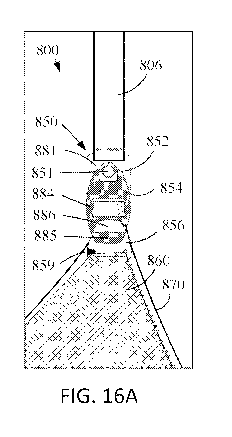
100571 FIG. 16A is a float view of a portion of a garment including the
engagement
mechanism of FIG. 14A, in a first configuration in which a first portion,
second portion and
third portion of the engagement mechanism are coupled together.
100581 FIG. 169 is a front view of the third portion of the engagement
mechanism and a
portion of an outer layer portion of the garment of FIG. 16A.
100591 FIG. 16C is a front view of a portion of the garment of FIG. 16A in a
second
configuration, showing an inner layer and the third portion of the engagement
mechanism and
outer layer removed.
100601 FIG. 16D is a front view of a portion of the garment of FIG. 16A in a
third
configuration, showing a support strap and the second portion and third
portion of the
engagement mechanism removed.
[0061] FIG. 17A is a front view of a garment, according to an embodiment.
[0062] FIG. 179 is an enlarged view of the region 179 of FIG. 17A.
100631 FIG. 17C is a front view of the garment of FIG. 17A shown with an outer
panel
removed for illustrative purposes.
100641 FIG. 17D is an enlarged view of the region 17D of FIG. 17C.
100651 FIG. 17E is a front view of the garment of FIG. 17A shown with the
inner panel and
the outer panel removed for illustrative purposes.
100661 FIG. 17F is an enlarged view of the region 17F of FIG. 17E.
100671 FIG. 18A is a front view of a garment, according to another embodiment.
6
CA 03049549 2019-07-05
WO 2018/136640
PCT/US2018/014245
100681 FIG. 18B is a front view of the garment of FIG. 18A shown with the
outer panel
removed for illustrative purposes.
100691 FIG. I9A is a from view of a portion of the garment of FIG. 18A with
the third
portion of the engagement mechanism and the outer panel detached from the
second portion
of the engagement mechanism.
[0070] FIG. I9B is a front view of a portion of the garment of FIG. 18B with
the third
portion of the engagement mechanism coupled to a selected loop of the extender
of the
garment of FIG. I SA.
[00711 FIG. 19C is a front view of a portion of the garment of FIG. 1_8A. with
the third
portion and second portion of the engagement mechanism detached from the first
portion of
the engagement mechanism and thus, the outer panel and inner panel detached
from the
support strap and shoulder strap.
100721 FIG. 191) is a back view of the extender of the garment of FIG. 18A.
100731 FIG. 20A is a front view of a garment, according, to another
embodiment.
100741 FIG 20B is a front view of the garment of FIG, 20A shown with the outer
panel
removed for illustrative purposes.
[0075] FIG. 21A is a front view of a portion of the garment of FIG. 20A with a
second
portion of the engagement mechanism and the outer panel detached from the
extender.
10076] FIG. 21B is a front view of a portion of the garment of FIG, 20A with
the second
portion of the engagement mechanism coupled to a selected loop of the
extender.
[00771 FIG. 21C is a back. view of a portion of the garment of FIG. 20A
illustrating the
attachment of the support strap to the extender.
[00781 FIG. 22 is a front view of a portion of a garment showing an
alternative attachment of
the support strap.
100791 FIG. 23A is a front view of a portion of a garment, according to
another embodiment,
shown with the outer panel detached from the extender.
100801 FIG. 23B is a front view of a portion of the garment of FIG. 23A shown
with the outer
7
CA 03049549 2019-07-05
WO 2018/136640
PCT/US2018/014245
panel attached to the extender.
100811 FIG. 23C is a front view of a portion of the garment of FIG. 23A shown
with the
extender removed for illustrative purposes.
100821 231) is
a back view of a portion of the garment of FIG. 23A showing the
shoulder strap attached to the support strap.
100831 FIG. 24 is a front view of a garment, according to another embodiment.
100841 FIG. 25 is a back view of the garment of FIG. 24.
100851 FIG. 26 is a back view of the garment of FIG. 24 with the inner pumpimg
panel
removed.
[0086] FIG. 27 is a front view of the pumping panel of the garment of FIG. 24.
100871 FIG. 28 is a back view of the pumping panel of the garment of FIG. 24.
100881 FIG. 29 is an enlarged perspective view of an engagement mechanism of
the garment
of FIG. 24.
100891 FIG. 30A is an enlarged front view of a portion of the garment of FIG.
24,
100901 FIG. 30B is an enlarged back view of a portion of the garment of FIG.
25.
100911 FIG. 30C is an enlarged back view of a portion of the garment of FIG.
26 with the
inner pumping panel removed.
100921 FIG-. 30D is an enlarged front view of a portion of the garment of FIG.
24 illustrating
the attachment of a support strap to the engagement mechanism.
100931 FIG. 3 is a front view of a garment, according to another embodiment.
100941 FIG. 32 is a back view of the garment of FIG. 31.
100951 FIG. 33 is a back view of the garment of FIG. 31 with the inner pumping
panel
removed.
100961 FIG. 34 is a front view of the pumping panel of the garment of FIG. 31.
8
CA 03049549 2019-07-05
WO 2018/136640
PCT/US2018/014245
100971 FIG 35 is a back view of the pumping panel of the garment of FIG. 31.
100981 FIG 36 is a front view of a garment and showing an enlarged view of an
engagement
mechanism, according to another embodiment.
100991 FIG 37 is a from view of the garment of FIG. 36 showing a neck strap
coupled to the
outer panel.
1001001 FIG. 38 is a front view of an inner pumping panel of the garment of
FIG. 36.
100101] FIG. 39A is a front view of a portion of the garment of FIG. 36
with the third
portion of the engagement mechanism and the outer panel detached from the
second portion
of the engagement mechanism..
[001021 FIG 39B is a front view of a portion of the garment of FIG. 36 with
the third
portion of the engagement mechanism coupled to a selected loop of the extender
of the
garment of FIG. 36.
E001031 FIG. 39C is a front view of a portion of the garment of FIG. 36
with the third
portion and second portion of the engagement mechanism detached from the first
portion of
the engagement mechanism and thus, the outer panel and inner panel detached
from the
support strap and shoulder strap.
[00104] FIGS. 40A-40C illustrate a side view, a back view and a front view,
respectively, of the extender of the garment of FIG. 36.
Detailed Description
[00105] Apparatuses, articles, processes for manufacture, garments,
bustiers, breast
pumping bras, and nursing bras that provide support to a wearer and/or at
least a portion of a
breast pump to aid with milk expression using a breast pump are described
herein. For
example, a garment, such as a bra, a tank top, a nightgown, or a bustler, may
provide support
for the weight of a breast pump body, milk container, and/or a wearer's
breast, help secure
the breast pump body in place, and/or stabilize the breast pump body for milk
expression.
Various embodiments may provide support to aid with creation of a tight seal
between the
wearer's breast and at least a portion of a breast pump body for milk
expression (e.g., a breast
shield and/or a let-down cushion of a breast pump body). The wearer of the
garment mr-iy be
9
CA 03049549 2019-07-05
WO 2018/136640
PCT/US2018/014245
able to pump breast milk without having to manually hold the breast pump body
against
themselves.
[00106] Garments
in accordance with some embodiments may have openings
forrnedldefined between layers of material that are fastened to2e-ther and/or
to panels of the
garment to provide openings for access to a wearer's breasts. In particular,
the garment may
have an inner panel (e.g., a pumping panel) having two openings providing
access to the
wearer's breasts that are formed between respective sets of layers of
material. The layers of
material can be coupled together such that at least a portion of the layers of
material overlap
each other, or alternatively can be coupled together in an abutting or edge-to-
edge
relationship. In some embodiments, the layers of material can be coupled
together such that a
portion of the layers overlap each other and a portion of the layers are
coupled together in an
abutting or edge-to-edge manner. Each opening is between the corresponding set
of layers of
material and the layers of material are fastened together in such a manner to
define/provide
the respective opening.
[00107] in some
embodiments, the garment may have an exterior surface of one or
more panels of material that cover the inner panel. When the panels of
material and the
layers of material that cover an opening are moved, the wearer can insert a
portion of the
breast pump body through the opening, and the layers of material and/or the
panels of
material of the garment can aid in supporting the breast pump body and/or the
wearer's
breast. In some embodiments, the materials used for the inner and the exterior
panels may be
a fabric capable of being stretched to allow for pushing the material out of
the way to insert
the pump body portion. The fabric may also have some elasticity to fit snugly
under and/or
around the pump body portion for support and be capable of returning to the
panel's original
shape. In some embodiments, the garment may have elastic edges to prevent the
garment
from slipping down as well as providing additional support for the wearer's
breasts.
[00108] In some
embodiments, a garment (e.g., a bra) described herein can include an
inner pumping panel with layers of material and an outer panel that can at
least partially
cover the inner pumping panel. A first portion of the layers of material of
the inner pumping
panel may be disposed on a left side of the bra to cover a portion of the
wearer's left breast
and can be fastened together such that at least a portion of the layers of
material overlap and
define a first opening. A second portion of the layers of material of the
inner pumping panel
may be disposed on a right side of the bra to cover a portion of the wearer's
right breast, and
CA 03049549 2019-07-05
WO 2018/136640
PCT/US2018/014245
can be fastened together such that at least a portion of the layers of
material overlap and
define a second opening. The first and second openings are each disposed at an
oblique angle
relative to a bottom edge of the bra and are sized and positioned to help
support at least a
portion of a breast pump disposable through the first and/or second opening
[00109] Some
embodiments may have one or more loops of a material (e.g., elastic,
fabric, etc.) attached to the garment. Each loop may be designed to secure a
portion of a
breast pump in place (e.g., a loop to hook or fit around a breast shield to
aid in the support of
the breast pump body and milk container for pumping milk).
[00110] Some
embodiments may have adjustable straps that may be selectively
attached to the garment. For example, the garment can have a top line on the
garment with
corresponding attachment mechanisms to those found on the strap thereby
allowing the strap
to be attached thereto. For example, the top line may be a piece of material
(e.g., an elastic
band) attached to an edge of a panel (e.g., an inner panel) and the
corresponding attachment
mechanisms may be sewn to the garment with stitching between the elastic band
and the
fabric of the garment, The one or more attachment mechanisms (e.g.,
corresponding
attachment mechanisms to the attachment mechanisms found on the strap) may be
sewn in to
the garment for selectively attaching a strap in one of a multiple different
positions to support
a breast pump body.
[00111] By way
of further example, a neck strap can optionally be used and may
extend around the back of the wearer's neck and be attached to the top line of
the garment.
The garment (e.g., a top line of a pumping/ nursing bra) may have one or more
selective
attachment mechanisms (e.g., loops or hooks allowing for attachment of the
strap to the
garment). Multiple selective attachment mechanisms may be provided on the
garment to
provide multiple different positions for the strap. Attachment mechanisms may
include, for
example, hooks that may be selectively attached to a loop (e.g., a fabric,
metal, or plastic
loop), snaps, buttons and button holes, ribbon ties, lace ties, string ties,
and/or any other
attachment mechanism that can be selectively attached or detached. For
example, a wearer
could use a ribbon, lace, heavy string, etc. that could be threaded through a
loop on the
topline and tied where the two ends join. There may be a single strap and/or
multiple straps
that extend from one area of the bra to another as opposed to fitting around
the neck. For
example, a single strap could attach at the front topline, extend over the
shoulder and hook at
the topline below the underarm or back.
11
CA 03049549 2019-07-05
WO 2018/136640
PCT/US2018/014245
[00112] In some
embodiments, the neck strap may have a single hook that can be
attached to the garment or multiple hooks that may be attached to the garment.
The neck
strap may be used, for example, to ensure that the garment remains in place
during breast
pumping, particularly when the breast pump bottle becomes heavier as the
container, which is
used with the breast pump to collect milk, fills with milk. For example, a
neck strap may
encircle the neck of the wearer and have at least one hook attached to the top
line of the
garment to ensure that the garment remains in place during the use of a breast
pump with at
least one of the wearer's breasts. The neck strap may be used with or without
shoulder straps
of the garment. In some embodiments, a neck strap can include a comfort strap
portion that
has a width that is greater than a width of a typical strap to provide further
comfort to the
user. For example, the comfort strap portion can extend around the user's
neck. In some
embodiments, the comfort strap portion of the neck strap can be padded and/or
can be formed
with a material to provide softer comfort to the user's neck. In some
embodiments, the width
of the comfort portion can vary. For example, the width can be tapered or
narrower at the
ends of the comfort portion than at a center of the comfbn portion.
[00113] In some
embodiments, a pocket or a channel may be provided on a shoulder
strap that contains and/or houses a cord or a strap with a hook or an
attachment piece to
connect to another area of the garment, as shown and described for example in
International
Application No. PCT/US16/43326 incorporated by reference above. The cord may
be elastic
to allow for the cord to be stretched and/or the cord may be stored within the
pocket or
channel rolled up into a coil, so that the cord can be extended and retracted.
The cord may
also have a slider to lengthen and shorten the strap as needed.
[00114] In some
embodiments, the garment can include openings or holes along a
perimeter top edge of the garment and the fastening mechanisms of the straps
can be received
therein to couple the straps to the garment. Such an embodiment is described
in more detail
below with reference to specific embodiments.
1001151 in some
embodiments, a garment as described herein can be used in
conjunction with a wearable breast pump and/or a wearable milk collection
device. In such a
garment, the garment can include an. extender in place of the inner panel and
the extender can
be used to selectively adjust the position of the outer layer (e.g., the bra
cup) to accommodate
the wearable breast pump. The wearable breast pump or collection device can be
positioned
between the user's breast and the outer panel of the garment. The extenders
can be attached
12
CA 03049549 2019-07-05
WO 2018/136640
PCT/US2018/014245
to a portion of the engagement mechanism (e.g., engagement mechanism 150) on
both the
right side and left side of the garment. The outer panel of the garment (e.g.,
the right outer
panel and the left outer panel) can be removably and selectively coupled to
the extender to
adjust the position and size of the outer panel in relation to the user's
breast and the wearable
breast pump or collection device.
[00116] Such
adjustment of the size and position of the outer panel (e.g., the bra cup)
may be desirable, for example, to prevent stretching of the cup portion (e.g.,
outer panel) of
the garment during use of the wearable breast pump or milk collection device.
Because such
devices are disposed between the breast and the cup portion of the garment,
and due to the
size of some such devices, the cup portion of the garment may stretch or lose
its form or
shape during use of such devices and may then provide reduced support to the
user's breast.
Examples of such a garment are described in more detail below with reference
to FIGS. 18A-
21C and FIGS. 36-39C.
[00117] Other
objects and advantages of the present invention will become apparent
from the following detailed description when viewed in conjunction with the
accompanying
drawings, which set forth certain embodiments of the invention. It should be
understood,
however, that the disclosed embodiments are merely exemplary of the invention,
which may
be embodied in various forms. Therefore, the details disclosed herein are not
to be
interpreted as limiting, but merely as a basis for teaching one skilled in the
art how to make
and/ or use the invention.
1001181 FIG. 1
is a schematic illustration of a garment 100. The garment 100 can be,
for example, in the form of a bra, to be worn around a chest or upper torso of
a wearer,
typically a woman, who may desire to express milk from one or both breasts
using a breast
pump. The garment 100 can include an outer panel 160, an inner panel 170, one
or more
support straps 180, one or more shoulder straps 106 and a back panel 120. In
some
embodiments, each shoulder strap 106 can be coupled to the outer panel 160,
the inner panel
170, and the support straps 180 via an engagement mechanism 150 (also referred
to herein as
a "clasp"). The support straps 180 can be coupled on a first end to the back
panel 120, and on
a second end to one of the shoulder straps 106 via the engagement mechanism
150. In
alternative embodiments, the support straps 180 can be attached to a lower
band of the
garment (not shown) rather than to the back panel 120. In some embodiments,
the back panel
120 and a lower band can be formed integrally. Each of the shoulder straps 106
can have a
13
CA 03049549 2019-07-05
WO 2018/136640
PCT/US2018/014245
first end coupled to the support strap 180 (via the engagement mechanism 150)
and a second
end coupled to the back panel 120 and/or a lower band or other portion of the
garment 100,
via, for example, stitching. The outer panel 160 and the inner panel 170 can
be attached to
the back panel 120 and/or along a bottom band of the garment 100, for example,
along a
bottom edge of the outer panel 160 and/or along a bottom edge of the inner
panel 170, via, for
example, sewing/stitching. Similarly, the outer panel 160 and the inner panel
170 can be
coupled together along at least a portion of a bottom edge and/or along at
least a portion of a
top edge of the outer panel 160 and the inner panel 170.
[001191 The
inner panel 170 and the outer panel 160 can each include one or more
panels each formed with one or more layers of material. For example, the outer
panel 160
can include a right outer panel (not shown in FIG. 1) and a left outer panel
(not shown in
FIG. 1). The inner panel 170 can include a right inner panel (not shown in
FIG. 1) and a left
inner panel (not shown in FIG. 1). The right inner panel and the left inner
panel can be
shaped and sized for coverage of a wearer's right breast and left breast,
respectively. Each of
the right inner panel and the left inner panel can include a first portion and
a second portion
that are coupled together such that a portion is unattached and can define an
opening between
the first portion and the second portion. In some embodiments, the first
portion and the
second portion can include an overlapping portion, which can define the
opening. The first
portion and the second portion can be separated by, for example, moving the
first portion and
the second portion away from each other, thereby creating the opening and
providing access
to the user's breast. A breast pump can then be inserted through the opening
and the inner
panel 170 can help support the breast pump during milk extraction.
[001201 In some
embodiments, the inner panel 170 can include one or more holes or
apertures defined in an upper edge of the inner panel 170. In some
embodiments, a separate
component defines the holes and is coupled to the inner panel 170. The holes
are described
in more detail, for example, with reference to holes 243 described below with
reference to
FIGS. 5A-5D. A center strap (not shown in FIG. 1) can be attached to the inner
panel 170 via
selective releasable engagement with any of the holes. The center strap can be
the same or
similar in structure and/or function to the center strap 246 described below.
[001211 The
engagement mechanism 150 can be used to allow the outer panel 160, the
inner panel 170, the shoulder strap 106 and the support strap 180 to be
releasably coupled to
one another in various configurations. For example, in some embodiments, at
least a portion
14
CA 03049549 2019-07-05
WO 2018/136640
PCT/US2018/014245
of the outer panel 160 can be releasably coupled to and decoupled from the
inner panel 170,
and at least a portion of the inner panel 170 can be releasably coupled to and
decoupled from
the support strap 180 and the shoulder strap 106. When the outer panel 160 is
coupled to the
inner panel 170, the inner panel 170 and the outer panel 160 can collectively
be coupled to
and decoupled from the support strap 180 and shoulder strap 106.
1001221 In some
embodiments, the engagement mechanism 150 can include two or
more portions (not shown in FIG-. 1), with each of the two or more portions
associated with at
least one of the outer panel 160, the inner panel 170, the support strap 180
and the shoulder
strap 106. Thus, the outer panel 160, the inner panel 170, the support strap
180 and the
shoulder strap 106 can be coupleable, to and decoupleable from one another via
the two or
more portions of the engagement mechanism 150. For example, in some
embodiments, the
engagement mechanism 150 can include a first portion that can be releasably
coupled to a
second portion, and the second portion can be releasably coupled to a third
portion. In some
embodiments, the engagement mechanism 150 can include a first portion and a
second
portion. The first portion can be coupled to the support strap 180 and
shoulder strap 106 and
the second portion can be coupled to the inner panel 170. In such an
embodiment, a separate
coupling mechanism can be used. to releasably couple the outer panel 160 to
the inner panel
170. For example, a coupling mechanism such as a snap mechanism, a hook and
loop
coupling, VELCRO, etc.
[00123] In some
embodiments, the engagement mechanism 150 can include a first
portion fixedly coupled to the support strap 180 and fixedly coupled to the
shoulder strap
106, a second portion fixedly coupled to the inner panel 170 and a third
portion fixedly
coupled to the outer panel 160. In such an embodiment, the second portion of
the
engagement mechanism 150 can be releasably coupled to the first portion to
couple the inner
panel 170 to the support strap 180 and the shoulder strap 106. The third
portion of the
engagement mechanism 150 can be releasably coupled to the second portion to
releasably
couple the outer panel 160 to the inner panel 170.
[00124] In some
embodiments, the two Or more portions of the clasp 150 can include
mating features. The mating features can include, for example, complementary
mating
shapes or any other suitable coupling mechanisms such that the two or more
portions of the
clasp 150 are releasably coupleable to and decoupleable from one another. The
outer panel
160, the inner panel 170, the support strap 180 and the shoulder strap 106 can
each be fixedly
CA 03049549 2019-07-05
WO 2018/136640
PCT/US2018/014245
coupled to a portion of the clasp 150 via any suitable coupling mechanism. For
example, in
some embodiments, a portion of the outer panel 160, the inner panel 170, the
support strap
180 and/or the shoulder strap 106 can be fixedly coupled to a portion of the
clasp 150 with
stitching as described in more detail herein.
1001251 In use,
the garment 100 can be worn around a chest or upper torso of a wearer.
If access to a breast of the wearer is desired, such as for breast pumping,
the outer panel 160
(e.g., the right outer panel and/or the left outer panel) can be detached from
the inner panel
170 (e.g., the right inner panel and/or the left inner panel) by detaching or
uncoupling the
third portion from the second portion of the engagement mechanism, 150. The
outer panel
160 can then be moved (e.g., folded down) such that the inner panel 170 is
accessible. As
described above, the first portion and the second portion of the inner panel
(e.g., the right
inner panel and/or the left inner panel) can be separated (e.g., stretched or
folded) to create an
opening through which the wearer's breast is accessible and a portion of a
breast pump can be
inserted. If further access to the breast of the wearer is desired, for
example, for nursing, the
inner panel 170 can be detached from the support strap 180 and shoulder strap
106 by
removing/detaching the second portion of the engagement mechanism 150 from the
first
portion of the engagement mechanism 150. Because the support strap 180 and
shoulder strap
106 remain coupled to the back panel 120, the garment 100 can still be held in
place on the
body of the wearer via the shoulder straps 106 and support straps 180. In some
embodiments,
the outer panel 160 and the inner panel 170 can be detached from shoulder
strap 106 and
support strap 180 simultaneously without decoupling the outer panel 160 from
the inner panel
170. When desired, the inner panel 170 and the outer panel 160 can be
reattached to shoulder
strap 106 and support strap 180 by recoupling the second portion to the first
portion of the
clasp 150, and the outer panel 160 can be recoupled to the inner panel 170.
[00126] FIGS. 2A-
2E illustrate various different views of a garment 200 in the form of
a bra, to be worn around a chest or upper torso of a wearer, typically a
woman, who may
desire to express milk from one or both breasts using a breast pump. FIG. 2A
illustrates a
front view of an assembled garment 200, which can include an inner panel or
pumping panel,
an exterior panel, and a back panel. The inner panel, exterior panel and back
panel can each
include one or more separate panel material portions to, for example, form a
right side panel
and a left side panel of the garment 200. For example, the exterior panel can
include a left
side panel and a right side panel. In addition, one or more layers of material
can be used to
16
CA 03049549 2019-07-05
WO 2018/136640
PCT/US2018/014245
form each of the inner panel (pumping panel), exterior panel andlor back
panel. For example,
the inner panel can include two, three, four or more layers of material
coupled together.
1001271 The
exterior pan& can include a first panel 202 and a second panel 204 (e.g., a
right side panel and a left side panel, respectively). The pumping panel can
include multiple
layers of material that are coupled together in such a manner to define an
opening or hole as
described in more detail below. The layers of material can be coupled together
such that at
least a portion of the layers of material overlap each other. In some
alternative embodiments,
the lay, ers of material may not overlap, but instead can be coupled together
in an abuttimg or
edge-to edge relationship to each other. In one embodiment, the layers of
material include a
center layer 210 (see, e.g., FIG. 2A), a left inner layer 214 (see, e.g., FIG,
2B) and a right
inner layer 212 (see, e.g.. FIG 2B), The garment 200 can include first and
second shoulder
straps 206 (also referred to as -shoulder straps") having a fastening
mechanism 216 coupled
to a first end, and a second end of each of first and second shoulder straps
206 being
attachable to first and second engagement mechanisms 250. The garment 200 also
includes
closures 221 and 222, a first wrap-around panel 232, and a second wrap-around
panel 234.
For ease of discussion, center layer of material 210 may also be referred to
herein as "center
layer 210."
[001281 The
components of garment .200 (e.g., panels and/or layers) may be made
from any appropriate material, including, but not limited to, fabric, cotton,
spandex, elastic,
polyester, rayon, and mesh. Where appropriate, one or more of the components
may be
fabricated to stretch or be temporarily reshaped and/or repositioned. In some
embodiments,
first panel 202 and second panel 204 may be made from a lightweight material
that may, in
some instances, include a decorative design or accent (e.g., lace or
decorative pattern). The
first panel 202 andlor the second panel 204 may serve to, for example, smooth
the exterior
surface of garment 200 to provide a seamless appearance when worn under
another garment
(e.g., shirt or blouse). in some embodiments, first panel 202 andlor second
panel 204 may
assist in the positioning, support, and/or retention of a portion of a breast
pump, such as a
breast shield 294 of a breast pump 290 (shown in FIGS. 7A and 7B), within an
opening 230.
Additionally, or alternatively, first panel 202 and/or second pan& 204 may
assist in the
positioning, support, and/or retention of a portion of a pumping container,
such as a pumping
container of the breast pump 290 (shown in FIGS. 7A and 7B) within opening
230, and/or a
breast pad, such as breast pad 240, which will be discussed in greater detail
below with
17
CA 03049549 2019-07-05
WO 2018/136640
PCT/US2018/014245
regard to FIGS. 4A-4C.
100129] First
and second wrap around panels 232 and 234 may be affixed to a portion
of, for example, the exterior panel or the pumping panel or the back panel, or
any
combination of these panels, and may serve to wrap around the body of a wearer
(typically
the side and back) so that the garment 200 may close around the wearer via
closures 221 and
222 in a manner similar to known garments/brassieres.
[001301 FIG, 2B
illustrates a front view of garment 200, without first panel 202 and
second panel 204 of the exterior panel to expose a left inner layer 214 and a
right inner layer
212. The left inner layer 214 may be situated on the left side of garment 200
(covering the
left breast), within the pumping panel, and arranged to partially overlap a
portion of center
layer 210 positioned on the left side of the garment 200. Left inner layer 214
may be
partially affixed (e.g., via sewing, chemical bonding, heat bonding, etc.) to
center layer 210 at
upper and/or lower affixed regions 225. A region, between the upper and lower
affixed
regions 225, where the left inner layer 214 and the center layer 210 are not
affixed to one
another defines an opening 230 between the left inner layer 214 and the center
layer 210.
1001311 The
right inner layer 212 may be situated on the right side of garment 200
(covering the right breast) and arranged to partially overlap a portion of
center layer 210
positioned on the right side of the garment .200. Right inner layer 212 may be
partially
affixed (e.g., via sewing, chemical bonding, heat bonding, etc.) to center
layer 210 at upper
andlor lower affixed regions 225. A region between the upper and lower affixed
regions 225
where the right inner layer 212 and the center layer 210 are not affixed to
one another defines
an opening 230 between the right inner layer 21.2 and the center layer 21Ø
[001321 In this
embodiment, an attachment line (e.g., stitching) of the affixed regions
225 between the right inner layer 212 and the center layer 210 and between the
left inner
layer 214 and the center layer 210 (e.g., overlapping material portions)
and/or opening(s) 230
are obliquely oriented at an angle relative to the bottom edge of the garment
200. Exemplaiy
angles for the attachment line of the partially overlapping and/or overlapped
left inner layer
214 and center layer 210 may include any angle within the range of about 300
to about 800
relative to the bottom edge of the garment 200. Exemplary angles for the
attachment line of
the partially overlapping and/or overlapped right inner layer 212 and center
layer 210 may
include any angle within the ranee of about 1000 to about 150 (i.e., about -
300 to about -80 )
18
CA 03049549 2019-07-05
WO 2018/136640
PCT/US2018/014245
relative to the bottom edge of the garment 200. Thus, each of the openings 230
is angled in a
direction upwardly from a center of the garment. In some embodiments, the
oblique
orientation of the openimi, 230 may be substantially (+1- 100/0) 450 or 135
for the openinu, 230
on the first and second side of garment 200, respectively. In some alternative
embodiments,
the angle of the attachment lines and openings 230 can be angled in an
opposite direction.
For example, the attachment line on the right side of the bra can angle
downwardly from a
top edge of the bra toward the wrap around panel 234 (e.g., at an angle in the
range of about
30' to about 80 relative to the bottom edge of the garment 200) and the
attachment line on
the left side of the bra can angle downwardly from a top edge of the bra
toward the wrap
around panel 232 (e.g., at an angle in the range of about 100 to about. 150
relative to the
bottom edge of the garment 200).
100133]
Opening(s) 230 may be sized and positioned within the garment 200 to allow
at least a portion of a breast pump, such as the breast shield 294 of the
breast pump, to be
inserted into the opening(s) 230 and contact the wearer's breast(s). In one
embodiment,
insertion of the breast shield 294 into opening 230 may be achieved by
separating a portion of
the center layer 210 positioned between affixed regions 225 from the left
inner layer 214
and/or the right inner layer 212. The separation may be achieved by lifting,
pushing and/or
pulling the center layer 210, the left inner layer 214, and/or the right inner
layer 212 into a
desired configuration. The overlapping portions of right inner layer 212 and
center layer 210
and left inner layer 214 and center layer 210 defining the openings 230
provide a width or
depth of material that defines a passageway to support at least a portion of
the breast pump
(e.g., breast shield 294) inserted therethrough.
100134] The
oblique angle of the opening(s) 230 can provide flexibility and movement
of the portion of the breast pump along the oblique angle of the opening 230
to, for example,
align with a nipple of the wearer's breast or breasts. Thus, a user/wearer can
have improved
ability to position the breast pump at a desired angle and/or orientation
within the opening
230. For example, the oblique angle of the opening 230 can allow the wearer to
reposition
the breast pump left-to-right and/or up/down within the opening 230. The
oblique opening
230 can also provide increased support of the breast pump as the pumping
container (e.g.,
milk bottle) increases in weight from collection of the expressed milk. In
some
embodiments, first panel 202 and/or second panel 204 may be moved or
repositioned by a
wearer to access opening(s) 230. In some cases, first panel 202 and/or second
panel 204 may
19
CA 03049549 2019-07-05
WO 2018/136640
PCT/US2018/014245
be removed, either from garment 200, or pulled down to expose center layer
210, left inner
layer 214, right inner layer 212 and/or opening 230. In some embodiments,
garment 200 may
not include first panel 202 and/or second panel 204. In these embodiments,
movement of the
center layer 210, left inner layer 214, and/or right inner layer 212 may
expose opening 230.
100135] FIG. 2C
illustrates a back or rear view of garment 200, which shows an
optional back panel 220. Back panel 220 may serve to provide structural
support for the
garment 200 as well as the wearer's breasts when worn. In some embodiments,
back panel
220 may be made of a material, or layers of material, that are more stiff
than, for example,
center layer 210, the left inner layer 214, the right inner layer 212, first
panel 202, and/or
second panel 204. Back panel 220 may be configured in a "w"-type of shape,
wherein there
is material for the back panel 220 in the center and sides and two curve-
shaped cutout
sections with no material. The curve-shaped cutout sections may be configured
to align with
and fit underneath/around the wearer's breasts. It will be understood by those
of skill in the
an that "material" as used herein is not limited to a single panel or layer of
fabric and may be
any combination materials or layers of material.
1001361 It
should be noted that in some instances, garment 200 may not include
optional back panel 220. In these instances, for example, a bottom edge of
first wrap around
panel 232, center layer 210, left inner layer 214, right inner layer 212,
and/or second wrap
around panel 234 may be affixed to one another arid/or to a strap (not shown)
or other
mechanism for facilitating the construction of garment 200 and/or the
attachment of closures
221 and 222. Additionally, when back panel 220 is not included in garment 200,
first and
second portions of engagement mechanisms 250 (described in detail below with
reference to
FIGS. 3A and 3B) may be attached to, for example, center layer 210, left inner
layer 214,
and/or right inner layer 212, respectively.
[001371
Additionally, center layer 210, left inner layer 214, right inner layer 212,
and
back pan& 220 may include one or more different layers, pieces of fabric,
panels, etc. affixed
(e.g., sewn, chemically bonded, etc.) to one another.
100138] FIG. 2D
provides a perspective illustration of the garment 200 showing how
first panel 202, second panel 204, center layer 210, left inner layer 214,
and/or right inner
layer 212 may extend perpendicularly or substantially perpendicularly, outward
from a planar
surface of garment 200 to, for example, accommodate a three dimensional shape
of a
CA 03049549 2019-07-05
WO 2018/136640
PCT/US2018/014245
wearer's breasts. Additionally, FIG 2D also illustrates that upper and/or
lower affixed
regions 225 are sewn and a region therebetween allows for opening 230. FIG. 2E
provides an
alternative rear view of garment 200 showing affixed regions 225 and openings
230.
100139] In some
embodiments, as shown in FIG. 3A, the engagement mechanisms 250
include a first engagement member 250A that can be coupled to (or engage or
attach to) a
second engagement member 250B (FIGS. 3A and 3B illustrate the first and second
engagement members decoupled or disengaged from each other). Engagement
members
250A can be attached to the back panel as shown in FIGS. 3A and 3B. Engagement
members
250B can be coupled to the center layer 210 as shown in FIG. 3A. The first and
second
engagement members 250A and 250B and/or an extension portion of back panels
220 may
each be affixed to a shoulder strap 206 sized and shaped to enable a wearer to
put on and take
off garment 200 as well as provide support for the wearer's breasts and
garment 200 when
worn. Shoulder straps 206 can include a first fastening member 216A, which
will be
discussed in greater detail below with reference to FIGS. 5A-5D.
1001401 FIG 3B
illustrates a back or rear view of garment 200, which shows the
extension portions of back panel 220 affixed to engagement members 250A when
the
engagement members 250A and 250B are not engaged together. When engagement
members
250A and 250B are not engaged together, a portion of center layer 210, left
inner layer 214,
right inner layer 212, first panel 202, and/or second panel 204 may be
decoupled from the
back panel 220 as shown. In this way, when worn by the wearer, the decoupled
engagement
members 250A and a portion of garment 200 affixed thereto may be repositioned
or moved to
expose a portion of the wearer's underlying breast(s).
10014 t I FIG. 4A
illustrates a breast pad 240 that can be removably inserted into
garment 200 between a portion of first panel 202 and a portion of the right
inner layer 212
and/or a portion of center layer 210 as shown in FIGS. 4B and 4C. Breast pad
240 may be
manufactured from, for example, fabric, foam, rubber or some combination
thereof Breast
pad 240 may be either disposable or reusable. When reusable, breast pads 240
may be
manufactured to be machine or hand washable. In some embodiments, breast pad
240 may
serve to smooth the exterior surface of garment 200, add volume to the garment
200, and/or
protect an underlying breast or nipple of the wearer.
[001421 FIGS. 5A-
5D provide illustrations of how the shoulder straps 206 can be
21
CA 03049549 2019-07-05
WO 2018/136640
PCT/US2018/014245
coupled to the garment 200. As described above, the straps 206 each include a
first fastening
member 216A coupled to an end thereof To couple the strap 206 to the body of
the garment
200, the first fastening members 216A can be coupled to a second fastening
member 216B
disposed along an upper/top perimeter portion of the body of the garment 200
as shown in
FIG. 5A. As shown in FIG. 5B, the second fastening member 216B can include,
for example,
a length of fabric or elastic material 241 that defines multiple openings or
holes 243 along a
length thereof In some embodiments, holes 243 may resemble button holes as
shown in FIG.
5B. The length of fabric or elastic material 241 may be affixed to, or sewn
into, a portion 247
(e.g., an upper edge) of garment 200. For example, in some embodiments, the
length of
fabric 241 can be disposed between the center layer 210 and the inner layers
212, 214 such
that the holes 243 defined in the length of fabric 241 are visible along a top
edge of the
garment 200.
1001431 FIGS. 5C
and 5D illustrate how a fastening member 216A affixed to a
shoulder strap 206 can be releasably coupled to a selected hole 243 of the
second fastening
member 216B. As best shown in FIGS. 5C and 5D, first fastening member 216A may
resemble a hook that can be inserted into a selected hole 243. The fastening
member 216A
can then be positioned within the hole 243 to be substantially parallel to a
plane of the second
fastening member 216B as fastened to garment 200 (see FIG. 5D). The first
fastening
member 216A may be securely and removably attached to a selected one of the
holes 243 of
fastening member 216B by virtue of its positioning or engagement within the
hole 243 and/or
via friction.
100144] As shown
in FIG. 5A, the garment 200 can include a fastening member 216B
at multiple locations along an upper perimeter of the garment 200. For
example, a first part
of fastening member 216B can be disposed along a portion of the upper
perimeter of garment
200 and a second part of fastening member 216B can be disposed along an
outside perimeter
of a portion of first wrap around panel 232 and second wrap around panel 234.
A portion of
the second part of the fastening member 216B may also be affixed to the upper
perimeter of
the center layer 210.
[001451 The
multiple holes 243 of second fastening member 216B provides
adjustability and allows a wearer to couple a strap 206 to the garment 200 at
various different
locations to, for example, improve the comfort of garment 200 when worn,
and/or provide
support for breast weight, a portion of the breast pump, and/or a container of
pumped breast
22
CA 03049549 2019-07-05
WO 2018/136640
PCT/US2018/014245
milk, (e.g., such as pumping container 100) as may be used when expressing
milk from a
breast. For example, as shown in FIGõ 6A, a wearer may couple the first
fastening member
216A of a first shoulder strap 206 to a hole 243 of second fastening member
216B at a
position on the second wrap around panel 234, and a second shoulder strap 206
with a first
fastening member 216A can be coupled to a hole 243 of second fastening
mechanism 216B at
a position on the first wrap around panel 232 closer to the center layer 210
than the first
shoulder strap 206. The adjustability of the attachment of the straps 206 to
the body of the
garment 200 allows a wearer to adjust the positioning of the straps 206 as
desired.
1001461 FIG. 6B
shows garment 200 being used with a center strap 246. The strap 246
can encircle the wearer's neck with a single loop and can have hooks 216 at
each end, in
some embodiments, the center strap 246 can be a neck strap that is a single
loop joined
together (e.g., sewn together) and that has a single attachment mechanism (not
shown) (e.g., a
hook). The strap 246 may encircle the wearer's neck and then extend down from
the
wearer's neck toward the garment 200, in some embodiments a neck strap 246 can
include a
comfort portion that has a greater width at a center of the comfort portion
than at the ends of
the comfort portion. The center strap 246 may include a first fastening member
216A, which
may be engaged with any available hole 243 of second fastening member 216B.
Often times,
center strap 246 may be engaged with the portion of the second fastening
member 216B
positioned along or coupled to the upper perimeter of the center layer 210, as
shown in FIG.
6B. The center strap 246 can help to keep the garment 200 in place by
providing additional
stability when the wearer is pumping breast milk, particularly when a breast
pump container
is full of milk.
[001471 It will
be appreciated that the configurations of the coupling of the first and
second fastening members 216A and 216B are not limited by the examples
provided by
FIGS. 6A and 6B. For example, a wearer may crisscross the shoulder straps 206
such that the
first fastening member 216A of the shoulder strap 206 on the right side of the
garment 200 is
coupled to the second fastening member 216B disposed on the wrap around panel
234 on the
left side of the garment 200. Additionally, or alternatively, a wearer may
position a first
fastening member 216A of center strap 246 in any available hole 243 of second
fastening
member 216B.
[001481 FIG. 7A
depicts the garment 200, showing second panel 204 and left inner
layer 214, and/or a portion of center layer 210 are repositioned to expose
opening 230. FIG.
23
CA 03049549 2019-07-05
WO 2018/136640
PCT/US2018/014245
7A also depicts a portion of first panel 202 pushed or moved downward to allow
access to
opening 230. Center layer 210 is separated from right inner layer 212 to
provide a
passageway for a portion of the breast pump (e.g., breast shield of breast
pump body 206)
through opening 230. In this fashion, the breast shield of breast pump body
296 may contact
an underlying breast of a wearer to express and/or pump breast milk from the
breast. Center
layer 210, first panel 202, and/or right inner layer 212 may act to support a
portion of the
weight of the breast shield, the breast pump body 296 and/or expressed milk
stored in
pumping container 290, and/or assist in securing the breast shield of breast
pump body 296
against the wearer's breast.
1001491 FIG. 7B
depicts a wearer using a breast pump, or a portion thereof, on the first
side (left side of wearer) while wearing garment 200 in a manner similar to
that depicted in
FIG. 7B.
1001501 FIGS. 8A-
9B illustrate various views and components of a garment 300. The
garment 300 can be the same or similar in structure andior function to any of
the garments
described herein, such as garment 100 or garment 200. For example, the garment
300 can
include an outer panel 360, an inner panel 370 (shown in FIG. 8C), and one or
more support
straps 380 (shown in FIG. 8E). The garment 300 can also include two shoulder
straps 306.
Each shoulder strap 306 can be coupled to the outer panel 360, the inner panel
370, and the
support straps 380 via an engagement mechanism 350 (also referred to herein as
a "clasp").
The support straps 380 can be coupled on a first end to a back panel 320 and
on a second end
to one of the shoulder straps 306 via the engagement mechanism. 350. In
alternative
embodiments, the support snap 380 can be attached to a lower band of the
garment 300 rather
than to the back panel 320. Each of the shoulder straps 306 can have a first
end coupled to
the support strap 380 (via the engagement mechanism 350) and a second end
coupled to the
back panel 320. The outer panel 360 and/or the inner panel 370 can be attached
to the back
panel 320, for example, along a bottom edge of the outer panel 360 and/or
along a bottom
edge of the inner panel 370, via, for example, sewing/stitching. Similarly,
the outer panel
360 and the inner panel 370 can be coupled together along at least a portion
of a bottom edge
and/or along at least a portion of a top edge of the outer panel 360 and the
inner panel 370.
1001511 The
inner panel 370 and the outer panel 360 can each include one or more
panels each formed with one or more layers of material. As shown, for example,
in FIG. 8A,
the outer panel 360 includes a right outer panel 362 and a left outer panel
364. As shown, for
24
CA 03049549 2019-07-05
WO 2018/136640
PCT/US2018/014245
example, in FIG. 8C, the inner panel 370 includes a right inner panel 312 and
a left inner
panel 314. The right inner panel 312 and the left inner panel 314 can be
shaped and sized for
coverage of a wearer's right breast and left breast, respectively. Each of the
right inner panel
312 and the left inner panel 314 can include a first portion 315 and a second
portion 317 that
are coupled together such that a portion is unattached and can define an
opening 330 (see
FIG. 8C) between the first portion 315 and the second portion 317. In some
embodiments,
the first portion 315 and the second portion 317 can include an overlapping
portion, which
can define the opening 330. The first portion 315 and the second portion 317
can be
separated by, for example, moving the first portion 315 and the second portion
317 away
from each other, thereby creating the opening 330 and providing access to the
user's breast.
A breast pump can then be inserted through the opening 330 and the inner panel
370 can help
support the breast pump during milk extraction.
1001521
Additionally, as shown in FIG. 8C, the inner panel 370 can include one or
more holes 343 defined in an upper edge of the inner panel 370. For example,
in some
embodiments, the inner panel 370 can define the holes 343. In some
embodiments, a separate
component defines the holes 343 and is coupled to the inner panel 370. The
holes 343 can be
the same or similar in structure and/or function to the holes 243 described
above with
reference to FIGS. 5A-5D. For example, a center strap 346 can be attached to
the inner panel
370 via releasable engagement with any of the holes 343. The center strap 346
can be the
same or similar in structure and/or function to the center strap 246 described
above.
1001531 The
engagement mechanism 350 can be the same or similar in structure and/or
function to any of the engagement mechanisms described herein, for example,
the
engagement mechanisms 150 and 250 described above. As shown in FIG. 8B, which
is an
enlarged view of the region 8B of FIG. 8A, in this embodiment, the engagement
mechanism
350 can include a first portion 352, a second portion 354, and a third portion
356. The first
portion 352 can be releasably coupleable to the second portion 354, and the
second portion
354 can be releasably coupleable to the third portion 356. The first portion
352 can include
an extension portion 351, a first opening 381, and a second opening 383 (best
shown in FIG.
8F) on an opposite side of the extension portion 351 than the first opening
381. The second
portion 354 can include a tab portion 353, a first opening 355, and a second
opening 357 on
an opposite side of the tab portion 353 than the first opening 355. The third
portion 356 can
include a hook portion 358 and an opening 359. The hook portion 358 can be,
for example,
CA 03049549 2019-07-05
WO 2018/136640
PCT/US2018/014245
an s-shaped hook similar to or the same as the fastener 216A shown in FIGS.
.5C and 5D.
100154j The
first portion 352 of the engagement mechanism 350 is coupled to one of
the shoulder straps 306 with, for example, stitching. For example, an end
portion of one of
the shoulder straps 306 can be looped through the first opening 381 and
attached to itself
(e.g., with stitching) such that the first portion 352 is secured within the
loop of the shoulder
strap 306. Additionally, the first portion 352 can be configured to receive a
portion of the
support strap 380 through the second opening 383 such that the support strap
380 can be
secured to the first portion 352 (see, e.g., FIGS. 8E and 8F). The extension
portion 351 of the
first portion 352 can be shaped and sized to be inserted through the first
opening 355 of the
second portion 354 to releasably couple the second portion 354 to the first
portion 352 and,
therefore, releasably couple the inner panel 370 to the support strap 380 as
described in more
detail below. The tab portion 353 of the second portion 354 can be shaped and
sized such
that when the extension portion 351 of the first portion 352 is received
through the first
opening 355 of the second portion 354, the tab portion 353 contacts or engages
the extension
portion 351 and is flexed or clicked into locking engagement with the first
portion 352 (see,
e.g., FIGS. 9A and 9B which illustrate in more detail the engagement of the
tab portion 353
and the extension portion 351 of the clasp 350). In some embodiments, the tab
portion 353
can be sufficiently elastic such that as the second portion 354 is moved into
engagement with
the first portion 352, the tab portion 353 can bend slightly and then snap
into locking
engagement.
1001551 For
example, FIGS. 9A and 9B are side views of the first portion 352 and the
second portion 354 of the engagement mechanism 350 in a first and second
configuration,
respectively. As shown in FIG. 9A, the extension portion 351 of the first
portion 352 can be
shaped and sized such that it can be inserted through the first opening 355 of
the second
portion 354. As described above, the tab portion 353 of the second portion 354
can be
shaped and sized such that when the extension portion 351 of the first portion
352 is received
through the first opening 355 of the second portion 354, the tab portion 353
contacts or
engages the extension portion 351 and can be flexed or clicked into locking
engagement with
the first portion 352, as shown in FIG. 9B. For example, to releasably engage
the second
portion 354 with the first portion 352, the extension portion 351 of the first
portion 352 can
be inserted through the first opening 355 of the second portion 354 as shown
in FIG. 9A.
Initially, the second portion 354 will be disposed at an angle relative to the
first portion 352
26
CA 03049549 2019-07-05
WO 2018/136640
PCT/US2018/014245
(as shown in FIG. 9A) and as the user moves the second portion 354 toward the
first portion
552, the tab portion 353 can Ilex past the extension portion 351 until the
second portion 354
is in an abutting planar relationship with the first portion 352, as shown in
FIG. 9B. The
engagement between the first portion 352 and the second portion 354 can be
reversed by
applying a pulling force to the second portion 354 sufficient to bend the tab
portion 353 past
the extension portion 351 until the tab portion 353 is disengaged with the
first portion 352.
1001561 In this
embodiment, to secure the inner panel 370 to the second portion 354 of
the clasp 350 the inner panel 370 can include a loop portion 311. More
specifically, as
shown, for example, in FIG. 8D, the loop portion 311 can be formed by passing
a portion of
the inner panel 370 through the second opening 357 of the second portion 354
of the clasp
350, folding it upon itself and stitching it to the inner panel 370.
Alternatively, the loop
portion 311 can be a separate component or piece of material that is inserted
through the
second opening 357 and secured to the inner panel 370 (e.g., with stitching).
Similarly, the
third portion 356 of the clasp 350 can receive a portion of the outer panel
360 within the
opening 359 in the third portion 356 such that the outer panel 360 can be
secured to the third
portion 356 of the clasp 350 in a similar manner as described for loop 311
(e.g., a portion of
the outer panel 360 being, for example, looped through the opening 359). The
hook portion
358 of the third portion 356 can be inserted and secured within a channel
defined by the loop
portion 311 of the inner panel 370 to releasably couple the hook portion 358
to the third
portion 356, and therefore, releasably couple the outer panel 370 to the inner
panel 360.
1001571 As shown
in FIGS. 8A and 8B and described above, the first portion 352 and
the second portion 354 of the engagement mechanism 350 can be engaged to
couple the inner
panel 370 (e.g., right and left inner panels 312 and 314) to the support
straps 380.
Additionally, the third portion 356 can be coupled to the second portion 354
by inserting the
hook 358 through the loop portion 311 of the inner panel 370 such that the
outer panel 360
(e.g., the right and left outer panels 362 and 364) covers the inner panel 370
(e.g., the right
and left inner panels 312 and 314). Although the outer panel 360 is shown as
covering the
entire inner panel 370 in FIG. 8A, in some embodiments, the outer panel 360
may only cover
a portion of the inner panel 370. For example, in some embodiments, the outer
panel 360
may cover only the cup portions of the inner panel 370.
[001581 FIG. 8C
is a front view of the garment 300 shown with the outer panel 360
completely removed for illustrative purposes. Although the garment 300 is
shown with the
27
CA 03049549 2019-07-05
WO 2018/136640
PCT/US2018/014245
outer panel 360 completely removed, it should be understood that the outer
panel 360 would
remain attached to the inner panel 370 when the third portion 356 has been
removed from the
loop portion. 311 of the inner panel 370. For example, as described above, the
outer panel
360 can be attached to the inner panel 370 along a portion of a bottom edge
and/or a portion
of a top edge of the inner panel 370 in the regions outside of the cup regions
via, for example,
sewing/stitching.
1001591 As shown
in. FIG. 8D, which is an enlarged view of the region 8D in FIG. 8C,
the outer panel 360 has been detached from the inner panel 370 by removing the
third portion
356 (i.e., removing the hook portion 358) from the loop portion 311 of the
inner panel 370.
Thus, the inner panel 370 is exposed and accessible by the user. As shown in
FIG. 8C, the
removal (e.g., folding down) of the left outer panel 364 and the right outer
panel 362 can
reveal the left inner panel 314 and the right inner panel 312. With the outer
panels 362
and/or 364 moved uncovering at least a portion of the inner panels 312 and/or
314, a user can
gain access to the openings 330 to insert a breast pump as described above.
[001601 FIG. 8E
is a front view of the garment 300 shown with the inner panel 370
completely removed for illustrative purposes. Thus, as shown in FIG. 8F, which
is an
enlarged view of the region 8F in FIG. 8E, when the outer panel 360 and the
inner panel 370
are both detached from the first portion 352 of the engagement mechanism 350
and from the
support strap 380, the garment 300 can still be held in. place on the body of
the wearer via the
shoulder straps 306 and support straps 380. Although the garment 300 is shown
in FIG. 8E
with the outer panel 360 and the inner panel 370 completely removed, it should
be
understood that the outer panel 360 and the inner panel 370 would remain at
least partially
attached to the back panel 320 when the second portion 354 has been decoupled
from the first
portion 352 of the engagement mechanism 350. For example, as described above,
the outer
panel 360 and/or the inner panel 370 can be attached to the back panel 320
along the bottom
edge of the outer panel 360 and/or inner panel 370 via, for example,
sewing/stitching.
[00161] In use,
the garment 300 can be worn by a wearer in the configuration of FIG.
8A. If access to a breast of the wearer is desired, such as for breast
pumping, the outer panel
360 (e.g., the right outer panel 362 and/or the left outer panel 364) can be
detached from the
inner panel 370 (e.g., the right inner panel 312 and/or the left inner panel
314) by detaching
or uncoupling the third portion 356 from the second portion 354 of the
engagement
mechanism 350 and the outer panel 360 can be moved (e.g., folded down) such
that the inner
28
CA 03049549 2019-07-05
WO 2018/136640
PCT/US2018/014245
panel 370 is accessible. As described above, the first portion 315 and the
second portion 317
of the inner panel 370 (e.g., the right inner panel 312 and/or the left inner
panel 314) can be
separated (e.g., stretched or folded) to create an opening 330 through which
the wearer's
breast is accessible and a portion of a breast pump can be inserted. If
further access to the
breast of the wearer is desired, the inner panel 370 can be detached from the
support strap
380 and shoulder strap 306 by removing/detaching the second portion 354 of the
engagement
mechanism 350 from the first portion 352 of the engagement mechanism 350. In
some
embodiments, the outer panel 360 and the inner panel 370 can be detached from
shoulder
strap 306 and support strap 380 simultaneously without removing the third
portion 356 from
the loop portion 311 of the inner panel 370. When desired, the inner panel 370
and the outer
panel 360 can be reattached to shoulder strap 306 and support strap 380 by
recoupling the
second portion 354 to the first portion 352 of the engagement mechanism, and
recoupling the
third portion 356 of the engagement mechanism 350 to the loop portion 311 of
the inner
panel 370.
1001621 FIGS. 10
and 11A-11C show various views and components of a garment 400.
The garment 400 can be the same or similar in structure and function to the
garment 300
shown in FIGS. 8A-9B and described above. For example, the garment 400 can
include an
outer panel 460 with a right outer panel 462 and a left outer panel 464, an
inner panel 470
(shown in FIG. 11B) with a right inner panel (not shown) and a left inner
panel 414 (shown
in FIGS. 11B and 11C), a support strap 480 (shown in FIG. 11C) and a back
panel 420. The
garment 400 can include two shoulder straps 406. Each shoulder strap 406 can
be coupled to
the outer panel 460, the inner panel 470, and the support strap 480 via an
engagement
mechanism 450 (also referred to herein as a "clasp") as described for the
previous
embodiment.
[001631 The
engagement mechanism 450 can be the same or similar in structure and/or
function to any of the engagement mechanisms described herein, such as
engagement
mechanism 350. As shown in FIG. 11A, which is a front view of a portion of the
garment
400, the engagement mechanism 450 can include a first portion 452, a second
portion 454,
and a third portion 456. The first portion 452 can be releasably engageable
with the second
portion 454, and the second portion 454 can be releasably coupleable to the
third portion 456.
The first portion 452 can include an extension portion 451, a first opening
481, and a second
opening 483 (best shown in FIG. 11C) on an opposite side of the extension
portion 451 than
29
CA 03049549 2019-07-05
WO 2018/136640
PCT/US2018/014245
the first opening 481. The second portion 454 can include a tab portion 453, a
first opening
455, and a second opening 457 on an opposite side of the tab portion 453 than
the first
opening 455. The third portion 456 can include a hook portion 458 and an
opening 459. The
hook portion 458 can be, for example, an s-shaped hook similar to or the same
as the fastener
216A shown in FIGS. 5C and 5D.
1001641 The
first portion 452 of the engagement mechanism 450 is coupled to one of
the shoulder straps 406, with for example, stitching. For example, an end
portion of one of
the shoulder straps 406 can be looped through the first opening 481 and
attached to itself such
that the first portion 452 is secured within the loop of the shoulder strap
406. Additionally,
the first portion 452 can be configured to receive a portion of the support
strap 480 through
the second opening 483 such that the support strap 480 can be secured to the
first portion 452
(see, e.g., FIG. 11C). The extension portion 451 of the first portion 452 can
be shaped and
sized to be inserted through the first opening 455 of the second portion 454
to releasably
couple the second portion 454 to the first portion 452, and therefore,
releasably couple the
inner panel 460 to the support strap 480 similarly as described above with
reference to FIGS.
9A and 9B. The tab portion 453 of the second portion 454 can be shaped and
sized such that
when the extension portion 451 of the first portion 452 is received through
the first opening
455 of the second portion 454, the tab portion 453 contacts or engages the
extension portion
451 and is flexed or clicked into locking engagement with the first portion
452. In some
embodiments, the tab portion 453 can be sufficiently elastic such that as the
second portion
454 is moved into engagement with the first portion 452, the tab portion 453
can bend
slightly and then snap into locking engagement.
[001651 As with
the previous embodiment, in this embodiment, to secure the inner
panel 470 to the second portion 454 of the clasp 450, the inner panel 470 can
include a loop
portion 411. More specifically, as shown, for example, in FIG. 11C, the loop
portion 411 can
be formed by passing a portion of the inner panel 470 through the second
opening 457 of the
second portion 454 of the clasp 450, folding it upon itself and stitching it
to the inner panel
470. Alternatively, the loop portion 411 can be a separate component or piece
of material
that is inserted through the second opening 457 and secured to the inner panel
470 (e.g., with
stitching). Similarly, the third portion 456 of the clasp 450 can receive a
portion of the outer
panel 460 within the opening 459 in the third portion 456 such that the outer
panel 460 can be
secured to the third portion 456 of the clasp 450 in a similar manner as
described for loop 411
CA 03049549 2019-07-05
WO 2018/136640
PCT/US2018/014245
(e.g., a portion of the outer panel 460 being, for example, looped through the
opening 459).
The hook portion 458 of the third portion 456 can be inserted and secured
within a channel
defined by the loop portion 411 of the inner panel 470 to releasably couple
the hook portion
458 to the third portion 456, and therefore, releasably couple the outer panel
370 to the inner
panel 360.
1001661 As shown
in FIG. 11A and described above, the first portion 452 and the
second portion 452 of the engagement mechanism 450 can be engaged such that
the inner
panel 470 is coupled to the support strap 480. Additionally, the third portion
456 can be
coupled to the second portion 454 via the loop portion 411 of the inner panel
470 such that
the outer panel 460 covers at least a portion of the inner panel 470. Although
the outer panel
460 is shown as coveting the entire inner panel 470 in FIG. 10, in some
embodiments, the
outer panel 460 can cover only a portion of the inner panel 470. For example,
in some
embodiments, the outer panel 460 can cover only the cup portions of the inner
panel 470.
[00167] FIG. 11B
is a front view of a portion of the garment 400 shown with the outer
panel 460 and the third portion 456 of the engagement mechanism 450 detached
from the
inner panel 470. Specifically, the outer panel 460 has been detached from the
inner panel 470
via removing the third portion 456 (i.e., removing the hook portion 358) from
the loop
portion 411 of the inner panel 470. Thus, by moving (e.g., folding down) the
outer panel
460, the inner panel 470 can be revealed, providing access to a user to
openings (not shown)
defined by the inner panel 470 as described above for previous embodiments.
1001681 FIG. 11C
is a front view of a portion of the garment 400 shown with the inner
panel 470 and the second portion 454 detached from the first portion 452. Each
of the
shoulder straps 406 can be attached to a back panel (not shown) of the garment
400 and to the
support strap 480 as described for garment 300. Thus, as shown in FIG. 11C,
when the outer
panel 460 and the inner panel 470 are both detached from the first portion 452
of the
engagement mechanism 450 and the support strap 480, the garment 400 can still
be held in
place on the body of the wearer via the shoulder straps 406 and support straps
380.
[00169] In use,
when the garment 400 is worn by a wearer, to gain access to a breast of
the wearer to, for example, extract milk using a breast pump, the outer panel
460 can be
detached from the inner panel 470 by unhooking the hook portion 458 from the
loop portion
411, and the outer panel 460 can be moved (e.g., folded down) such that the
inner panel 470
31
CA 03049549 2019-07-05
WO 2018/136640
PCT/US2018/014245
is accessible. If further access to the breast of the wearer is desired, the
inner panel 470 can
be detached from the support strap 480 and the shoulder strap 406 by removing
the second
portion 454 of the engagement mechanism 450 from the first portion 452 of the
engagement
mechanism 450. In some embodiments, the outer panel 460 and the inner panel
470 can be
detached from the shoulder strap 406 and support strap 480 simultaneously
without removing
the third portion 456 of the engagement mechanism 450 from the loop portion
411 of the
inner panel 470. When desired, the inner panel 470 and the outer panel 460 can
be reattached
to the shoulder strap 406 and support strap 480 by recoupling the first
portion 452 of the
engagement mechanism 450 to the second portion 454 of the engagement mechanism
450,
and recoupling the first portion 452 to the loop portion 411 of the inner
panel 470.
1001.701 FIGS.
12A-12F illustrate various views and components of a garment 600.
FIG. 12A is a front view of the garment 600 in a first configuration. The
garment 600 can be
the same or similar in structure and/or function to any of the garments
described herein, such
as the gurnent 100 or the garment 300. For example, the garm.ent 600 can
include an outer
panel 660, an inner panel 670 (shown in FIG. 12C), and a support strap 680
(shown in FIG.
12E). The garment 600 can include two shoulder straps 606. Each shoulder strap
606 can be
coupled to the outer panel 660, the inner panel 670, and the support strap 680
via an
engagement mechanism 650 (also referred to herein as a "clasp").
[001.71] The
support straps 680 can be coupled on a first end to a back panel 620 and
on a second end to one of the shoulder straps 606 via the engagement mechanism
650. In
alternative embodiments, the support strap 680 can be attached to a lower band
of the
garment 600 rather than to the back panel 620. Each of the shoulder straps 606
can have a
first end coupled to the support strap 680 (via the engagement mechanism 650)
and a second
end coupled to the back panel 620. The outer panel 660 and/or the inner panel
670 can be
attached to the back panel 620, for example, along a bottom edge of the outer
panel 660
and/or along a bottom. edge of the inner panel 670, via, for example,
sewing/stitching.
Similarly, the outer panel 660 and the inner panel 670 can be coupled together
along at least a
portion of a bottom edge and/or along at least a portion of a top edge of the
outer panel 660
and the inner panel 670.
[00172] The
inner panel 670 and the outer panel 660 can each include one or more
panels each formed with one or more layers of material. As shown, for example,
in FIG.
12A, the outer panel 660 includes a right outer panel 662 and a left outer
panel 664. As
32
CA 03049549 2019-07-05
WO 2018/136640
PCT/US2018/014245
shown, for example, in FIG. 12C, the inner panel 670 includes a right inner
panel 612 and a
left inner panel 614. The right inner panel 612 and the left inner panel 614
can be shaped and
sized for coverage of a wearer's right breast and left breast, respectively.
Each of the right
inner panel 612 and the left inner panel 614 can include a first portion 615
and a second
portion 617 that are coupled together such that a portion is unattached and
can define an
opening 630 (see FIG. 12C) between the first portion 615 and the second
portion 617. In
some embodiments, the first portion 615 and the second portion 617 can include
an
overlapping portion which can define the opening 630. The first portion 615
and the second
portion 617 can be separated by, for example, moving the first portion 615 and
the second
portion 617 away from each other, thereby creating the opening 630 and
providing access to
the user's breast. A breast pump can then be inserted through the opening 630
and the inner
panel 670 can help support the breast pump during milk extraction.
1001731
Additionally, as shown in FIGS. 12C and 12D, the inner panel 670 can include
one or more holes 643 defined in an upper edge of the inner panel 670. For
example, in some
embodiments, the inner panel 670 can define the holes 643 and/or the holes 643
can be
defined by a separate component coupled to the inner panel 670. As described
for previous
embodiments, a center strap 646 can be attached to the inner panel 670 via
selective
releasable engagement with any of the holes 643. The center strap 646 can be
the same or
similar in structure and/or function to the center strap 246 described above.
1001741 The
engagement mechanism 650 can be the same or similar in structure and/or
function to any of the engagement mechanisms described herein, such as
engagement
mechanism 250 and/or engagement mechanism 350. As showri in FIG. 12B, which is
an
enlarged view of the region 12B of FIG. 12A, in this embodiment, the
engagement
mechanism 650 includes a first portion 652 and a second portion 654. The first
portion 652
can be releasably engageable with the second portion 654 in the same manner as
described
above for engagement mechanism 350. In this embodiment, the outer panel 660
can be
releasably coupled to the inner panel with a snap coupling 663. The snap
coupler 663 can be
configured to releasably couple a portion of the outer panel 660 to a portion
of the inner panel
670 as described in more detail below. The first portion 652 of the engagement
mechanism
650 can include an extension portion 651, a first opening 681, and a second
opening 683 (best
shown in FIG. 12F) on an opposite side of the extension portion 651 than the
first opening
681. The second portion 654 of the engagement mechanism 650 can include a tab
portion
33
CA 03049549 2019-07-05
WO 2018/136640
PCT/US2018/014245
653, a first opening 655, and a second opening 657 on an opposite side of the
tab portion 653
than the first opening 655. The snap coupler 663 can include a snap feature.
For example, in
some embodiments, the snap coupler 663 can include a first snap feature 663A
secured to the
outer panel 660 and a second complementary snap feature 663B secured to the
inner panel
670.
1001751 The
first portion 652 of the engagement mechanism 650 is coupled to one of
the shoulder straps 606 with, for example, stitching in the same manner as
described above
for engagement mechanism 650. For example, an end portion of one of the
shoulder straps
606 can be looped through the first opening 681 and attached to itself such
that the first
portion 652 is secured within the loop of the shoulder strap 606.
Additionally, the first
portion 652 of the engagement mechanism 650 can receive a portion of the
support strap 680
through the second opening 683 such that the support strap 680 can be secured
to the first
portion 652 (see, e.g., FIGS. 12E and 12F). The extension portion 651 of the
first portion
652 can be shaped and sized to be inserted through the first opening 655 of
the second
portion 654 to releasably couple the second portion 654 to the first portion
652 and, therefore,
releasably couple the inner panel 670 to the support strap 680 similarly as
described above
with reference to FIGS. 9A and 9B. The tab portion 653 of the second portion
654 can be
shaped and sized such that, when the extension portion 651 of the first
portion 652 is received
through the first opening 655 of the second portion 654, the tab portion 653
contacts or
engages the extension portion 651 and is flexed or clicked into locking
engagement with the
first portion 652. In some embodiments, the tab portion 653 can be
sufficiently elastic such
that as the second portion 654 is moved into engagement with the first portion
652, the tab
portion 653 can bend slightly and then snap into locking engagement.
[00176j In this
embodiment, to secure the inner panel 670 to the second portion 654 of
the clasp 650, the inner panel 670 can include a loop portion 611. More
specifically, as
shown, for example, in FIG. 12D, the loop portion 611 can be formed by passing
a portion of
the inner panel 670 through the second opening 657 of the second portion 654
of the clasp
650, folding it upon itself and stitching it to the inner panel 670.
Alternatively, the loop
portion 611 can be a separate component or piece of material that is inserted
through the
second opening 657 and secured to the inner panel 670 (e.g., with stitching).
[001771 As shown
in FIGS. 12A and 12B and described above, the first portion 652
and the second portion 654 of the engagement mechanism 650 can be engaged to
releasably
34
CA 03049549 2019-07-05
WO 2018/136640
PCT/US2018/014245
couple the inner panel 670 (e.g., right inner panel 612 and left inner panel
614) to the support
straps 680. Additionally, the snap coupler 663 can releasably couple the outer
panel 660
(e.g., the right outer panel 662 and the left outer panel 664) to the inner
panel 670 (e.g., right
inner panel 612 and left inner panel 614) such that the outer panel 660
substantially covers
the inner panel 670 by coupling the first snap feature 663A secured to the
outer panel 660
with the second complem.entaiy snap feature 663B secured to the inner panel
670. Although
the outer panel 660 is shown as covering the entire inner panel 670 in FIG.
12A, in some
embodiments, the outer panel 660 can only cover a portion of the inner panel
670. For
example, in some embodiments, the outer panel 660 can cover only the cup
portions of the
inner panel 670.
1001.781 FIG. 12C
is a front view of the garment 600 shown with the outer panel 660
completely removed for illustrative purposes. Although the garment 600 is
shown with the
outer panel 660 completely removed, it should be understood that the outer
panel 660 would
remain attached to the inner panel 670 when the first snap feature 663A. of
the outer panel
660 has been decoupled from the second snap feature 663B of the inner panel
670. For
example, as described above, the outer panel 660 can be attached to the inner
panel 670 along
a portion of the upper edges and/or along a portion of the bottom edges of the
inner panel 670
in the regions outside of the cup regions via, for example, sewing/stitching.
[001.79] As shown
in. FIG. 12D, which is an. enlarged view of the region 12D in FIG.
12C, the left outer panel 664 has been detached from the left inner panel 6614
by removing
(i.e., unsnapping) the first snap feature 663A of the outer panel left outer
panel 664 from the
second snap feature 663B of the left inner panel 614. Thus, the left inner
panel 614 is
exposed and accessible by the user. As shown in FIG. 12C, detaching and moving
(e.g.,
folding down) the outer panels 662 and 664 can reveal the right inner panel
612 and the left
inner panel 614. With the outer panels 662 and/or 664 moved uncovering at
least a portion of
the inner panels 612 and/or 614, a user can gain access to the openings 630 to
insert a breast
pump as described above.
100180] FIG. 12E
is a front view of the garment 600 shown with the inner panel 670
completely removed for illustrative purposes. Thus, as shown in FIG. 12F,
which is an
enlarged view of the region 12F in. FIG. 12E, when the outer panel 660 and the
inner panel
670 are both detached from the support strap 680, the garment 600 can still be
held in place
on the body of the wearer via the shoulder straps 606 and support straps 680.
Although the
CA 03049549 2019-07-05
WO 2018/136640
PCT/US2018/014245
garment 600 is shown in FIG. 12E with the outer panel 660 and the inner panel
670
completely removed, it should be understood that the outer panel 660 and the
inner panel 670
would remain at least partially attached to the back panel 620 when the second
portion 654
has been decoupled from the first portion 652 of the engagement mechanism 650
and the
outer panel 660 is detached from the inner panel 670. For example, as
described above, the
outer panel 660 and/or the inner panel 670 can be attached to the back panel
620 along the
bottom edge of the outer panel 660 and/or inner panel 670 via, for example,
sewing/stitching.
1001811 In use,
the garment 600 can be worn by a wearer and if access to a breast of
the wearer is desired, such as for breast pumping, the first snap feature 663A
can be detached
from the second snap feature 663B such that the outer panel 660 (right outer
panel 662 and/or
left outer panel 664) can be moved (e.g., folded down) relative to the inner
panel 670 and
such that the inner panel 670 is accessible. The first portion 615 and the
second portion 617
of the inner panel 670 (e.g., the right inner panel 612 and/or the left inner
panel 614) can be
separated (e.g., stretched or folded) to create an opening such that the
wearer's breast is
accessible through the opening 630. If further access to the breast of the
wearer is desired,
the inner panel 670 can be detached from the support strap 680 and shoulder
strap 606 by
removing the second portion 654 of the engagement mechanism 650 from the first
portion
652 of the engagement mechanism 650. When desired, the inner panel 670 and the
outer
panel 660 can be reattached to the support strap 680 and the shoulder strap
606 by recoupling
the second portion 654 to the first portion 652, and recoupling the first snap
portion 663A to
the second snap portion 663B.
[001821 FIGS.
13A-13F illustrate various views and components of a garment 700.
The garment 700 can be the same or similar in structure and/or function to any
of the
garments described herein, such as the garment 100 or the garment 600. For
example, the
garment 700 can include an outer panel 760, an inner panel 770 (shown in FIG.
13C), and a
support strap 780 (shown in FIG. 13E). The garment 700 can include two
shoulder straps
706. Each shoulder strap 706 can be coupled to the outer panel 760, the inner
panel 770, and
the support strap 780 via an engagement mechanism 750 (also referred to herein
as a
"clasp").
[001831 The
support straps 780 can be coupled on a first end to a back panel 720 and
on a second end to one of the shoulder straps 606 via the engagement mechanism
750. In
alternative embodiments, the support strap 780 can be attached to a lower band
of the
36
CA 03049549 2019-07-05
WO 2018/136640
PCT/US2018/014245
garment 700 rather than to the back panel 720. Each of the shoulder straps 706
can have a
first end coupled to the support strap 780 (via the engagement mechanism 750)
and a second
end coupled to the back panel 720. The outer panel 760 and/or the inner panel
770 can be
attached to the back panel 720, for example, along a bottom edge of the outer
panel 760
and/or along a bottom edge of the inner panel 770, via, for example,
sewing/stitching.
Similarly, the outer panel 760 and the inner panel 770 can be coupled together
along at least a
portion of a bottom edge and/or along at least a portion of a top edge of the
outer panel 760
and the inner panel 770.
100184j The
inner panel 770 and the outer panel 760 can each include one or more
panels each formed with one or more layers of material. As shown, for example,
in FIG.
13A, the outer panel 760 includes a right outer panel 762 and a left outer
panel 764. As
shown, for example, in FIG. 13C, the inner panel 770 includes a right inner
panel 712 and a
left inner panel 714. The right inner panel 712 and the left inner panel 714
can be shaped and
sized for coverage of a wearer's right breast and left breast, respectively.
Each of the right
inner panel 712 and the left inner panel 714 can include a first portion 715
and a second
portion 717 that are coupled together such that a portion is unattached and
can define an
opening 730 (see FIG. 13C) between the first portion 715 and the second
portion 717. In
some embodiments, the first portion 715 and the second portion 717 can include
an
overlapping portion which can define the opening 730. The first portion 715
and the second
portion 717 can be separated by, for example, moving the first portion 715 and
the second
portion 717 away from each other, thereby creating the opening 730 and
providing access to
the user's breast. A breast pump can then be inserted through the opening 730
and the inner
panel 770 can help support the breast pump during milk extraction.
[00185]
Additionally, as shown in FIGS. 13C and 13D, the inner panel 770 can include
one or more holes 743 defined in an upper edge of the inner panel 770. For
example, in some
embodiments, the inner panel 770 can define the holes 743 and/or the holes 743
can be
defined by a separate component coupled to the inner panel 770. As described
for previous
embodiments, a center strap 746 can be attached to the inner panel 770 via
selective
releasable engagement with any of the holes 743. The center strap 746 can be
the same or
similar in structure and/or function to the center strap 246 described above.
Additionally, as
shown in FIG. 13C, the inner panel 770 can also include a center hole 743A for
attachment of
the center strap in the center of the garment 700.
37
CA 03049549 2019-07-05
WO 2018/136640
PCT/US2018/014245
1001861 The
engagement mechanism 750 can be the same or similar in structure and/or
function to any of the engagement mechanisms described herein, such as
engagement
mechanisms 350 or 650. As shown in FIG. 13B, which is an enlarged view of the
region 1313
of FIG. 13A, in this embodiment, the engagement mechanism 750 includes a first
portion 752
and a second portion 754. The first portion 752 can be releasably engageable
with the second
portion 754 in the same manner as described above for engagement mechanism
750. In this
embodiment, the outer panel 760 can be releasably coupled to the inner panel
with a snap
coupling 763. The snap coupler 763 can be configured to releasably couple a
portion of the
outer panel 760 to a portion of the inner panel 770 as described in more
detail below. The
first portion 752 of the engagement mechanism 750 can include an extension
portion 751, a
first opening 781, and a second opening 783 (best shown in FIG. 13F) on an
opposite side of
the extension portion 751 than the first opening 781. The second portion 754
of the
engagement mechanism 750 can include a tab portion 753, a first opening 755,
and a second
opening 757 on an opposite side of the tab portion 753 than the first opening
755. The snap
coupler 763 can include a snap feature. For example, in some embodiments, the
snap coupler
763 can include a first snap feature 763A secured to the outer panel 760 and a
second
complementary snap feature 76313 secured to the inner panel 770.
1001871 The
first portion 752 of the engagement mechanism 750 is coupled to one of
the shoulder straps 706 with, for example, stitching in the same manner as
described above
for engagement mechanism 750. For example, an end portion of one of the
shoulder straps
706 can be looped through the first opening 781 and attached to itself such
that the first
portion 752 is secured within the loop of the shoulder strap 706.
Additionally, the first
portion 752 of the engagement mechanism 750 can receive a portion of the
support strap 780
through the second opening 783 such that the support strap 780 can be secured
to the first
portion 752 (see. e.g., FIGS. 13E and 13F). The extension portion 751 of the
first portion
752 can be shaped and sized to be inserted through the first opening 755 of
the second
portion 754 to releasably couple the second portion 754 to the first portion
752 and, therefore,
releasably couple the inner panel 770 to the support strap 780 similarly as
described above
with reference to FIGS. 9A and 9B. The tab portion 753 of the second portion
754 can be
shaped and sized such that, when the extension portion 751 of the first
portion 752 is received
through the first opening 755 of the second portion 754, the tab portion 753
contacts or
engages the extension portion 751 and is flexed or clicked into locking
engagement with the
first portion 752. In some embodiments, the tab portion 753 can be
sufficiently elastic such
38
CA 03049549 2019-07-05
WO 2018/136640
PCT/US2018/014245
that as the second portion 754 is moved into engagement with the first portion
752, the tab
portion 753 can bend slightly and then snap into locking engagement.
1001881 In this
embodiment, to secure the inner panel 770 to the second portion 754 of
the clasp 750, the inner panel 770 can include a loop portion 711 (see, e.g.,
FIG. 13B). More
specifically, as shown, for example, in FIG. 13D, the loop portion 711 can be
formed by
passing a portion of the inner panel 770 through the second opening 757 of the
second
portion 754 of the clasp 750, folding it upon itself and stitching it to the
inner panel 770.
Alternatively, the loop portion 711 can be a separate component or piece of
material that is
inserted through the second opening 757 and secured to the inner panel 770
(e.g., with
stitching).
[001891 As shown
in FIGS. 13A and 13B and described above, the first portion 752
and the second portion 754 of the engagement mechanism 750 can be engaged to
releasably
couple the inner panel 770 (e.g., right inner panel 712 and left inner panel
714) to the support
straps 780. Additionally, the snap coupler 763 can releasably couple the outer
panel 760
(e.g., the right outer panel 762 and the left outer panel 764) to the inner
panel 770 (e.g., right
inner panel 712 and left inner panel 714) such that the outer panel 760
substantially covers
the inner panel 770 by coupling the first snap feature 763A secured to the
outer panel 760
with the second complementary snap feature 763B secured to the inner panel
770. Although
the outer panel 760 is shown as covering the entire inner panel 770 in FIG.
13A, in some
embodiments, the outer panel 760 can only cover a portion of the inner panel
770. For
example, in some embodiments, the outer panel 760 can cover only the cup
portions of the
inner panel 770.
[001901 FIG. 13C
is a front view of the garment 700 shown with the outer panel 760
completely removed for illustrative purposes. Although the garment 700 is
shown with the
outer panel 760 completely removed, it should be understood that the outer
panel 760 would
remain attached to the inner panel 770 when the first snap feature 763A of the
outer panel
760 has been decoupled from the second snap feature 763B of the inner panel
770. For
example, as described above, the outer panel 760 can be attached to the inner
panel 770 along
a portion of the upper edges and/or along a portion of the bottom edges of the
inner panel 770
in the regions outside of the cup regions via, for example, sewing/stitching.
[001911 As shown
in FIG. 13D, which is an enlarged view of the region 13D in FIG.
39
CA 03049549 2019-07-05
WO 2018/136640
PCT/US2018/014245
13C, the left outer panel 764 has been detached from the left inner panel 714
by removing
(i.e., unsnapping) the first snap feature 763A of the outer panel left outer
panel 764 from the
second snap feature 763B of the left inner panel 714. Thus, the left inner
panel 714 is
exposed and accessible by the user. As shown in FIG. 13C, detaching and moving
(e.g.,
folding down) the outer panels 762 and 764 can reveal the right inner panel
712 and the left
inner panel 714. With the outer panels 762 and/or 764 moved uncovering at
least a portion of
the inner panels 712 and/or 714, respectively, a user can gain access to the
openings 730 to
insert a breast pump as described above.
100192j FIG. 13E
is a front view of the garment 700 shown with the inner panel 770
completely removed for illustrative purposes. Thus, as shown in FIG. 13F,
which is an
enlarged view of the region 13F in FIG. 13E, when the outer panel 760 and the
inner panel
770 are both detached from the support strap 780, the garment 700 can still be
held in place
on the body of the wearer via the shoulder straps 706 and support straps 780.
Although the
garment 700 is shown in FIG. 13E with the outer panel 760 and the inner panel
770
completely removed, it should be understood that the outer panel 760 and the
inner panel 770
would remain at least partially attached to the back panel 720 when the second
portion 754
has been decoupled from the first portion 752 of the engagement mechanism 750
and the
outer panel 760 is detached from the inner panel 770. For example, as
described above, the
outer panel 760 and/or the inner panel 770 can be attached to the back panel
720 along the
bottom edge of the outer panel 760 and/or inner panel 770 via, for example,
sewing/stitching.
1001931 In use,
the garment 700 can be worn by a wearer and if access to a breast of
the wearer is desired, such as for breast pumping, the first snap feature 763A
can be detached
from the second snap feature 763B such that the outer panel 760 (right outer
panel 762 and/or
left outer panel 764) can be moved (e.g., folded down) relative to the inner
panel 770 and
such that the inner panel 770 is accessible. The first portion 715 and the
second portion 717
of the inner panel 770 (e.g., the right inner panel 712 and/or the left inner
panel 714) can be
separated (e.g., stretched or folded) to create an opening 730 such that the
wearer's breast is
accessible through the opening 730. If further access to the breast of the
wearer is desired,
the inner panel 770 can be detached from the support strap 780 and the
shoulder strap 706 by
removing the second portion 754 of the engagement mechanism 750 from the first
portion
752 of the engagement mechanism 750. When desired, the inner panel 770 and the
outer
panel 760 can be reattached to the support strap 780 via recoupling the second
portion 754 to
CA 03049549 2019-07-05
WO 2018/136640
PCT/US2018/014245
the first portion 752, and recoupling the first snap portion 763A to the
second snap portion
763B.
[00194] FIGS.
14A-15C illustrate an engagement mechanism 850 (also referred to
herein as a "clasp"), according to an embodiment that can be used to
releasably couple the
shoulder straps, support strap, inner panels and outer panels of a garment 800
(see, FIGS.
16A-16D). The garment 800 can be the same as or similar to the embodiments of
a garment
described herein (e.g., 200, 300, 400, 600, 700 described above). FIG. 14A is
a perspective
view of the engagement mechanism 850. As shown in FIG. 14A, the engagement
mechanism
850 can include a first portion 852, a second portion 854, and a third portion
856. The first
portion 852 can be configured to be releasably engageable with the second
portion 854.
Similarly, the second portion 854 can be configured to be releasably
engageable with the
third portion 856. The first portion 852 can include an extension portion 851,
a first opening
881, and a second opening 883 (best shown, for example, in FIG. 14B) on an
opposite side of
the extension portion 851 than the first opening 881. The second portion 854
can include a
tab portion 853, a first opening 855, a securement bar 884, a second opening
867, a third
opening 868, and an engagement portion 885. The third portion 856 can include
an
engagement portion 886 and an opening 859.
[00195] FIGS.
14B-14D are a front view, back view and side view, respectively, of the
first portion 852 of the clasp 850. The first portion 852 of the engagement
mechanism 850
can be coupled to a shoulder strap 806 of the garment 800 as described in more
detail below,
with, for example, stitching. For example, an end portion of the shoulder
strap 806 can be
looped through the first opening 881 and attached to itself such that a top
portion of the first
portion 852 is secured within the loop of the shoulder strap. Additionally,
the first portion
852 can receive a portion of a support strap 880 of the garment 800 through
the second
opening 883 such that the support strap 880 can be secured to the first
portion 852 of the
engagement mechanism 850. For example, an end portion of the support strap 880
can be
looped through the second opening 883 of the first portion 852 and attached to
itself (e.g.,
with stitching) such that a bottom portion of the first portion 852 is secured
within the loop of
the support strap 880.
[00196] FIGS.
14E-14G are a front view, a back view and a side view, respectively, of
the second portion 854 of the clasp 850. The first opening 855 of the second
portion 852 can
be shaped and sized such that the first opening 855 can receive the extension
portion 851 of
41
CA 03049549 2019-07-05
WO 2018/136640
PCT/US2018/014245
the first portion 852 similarly as described above with reference to FIGS. 9A
and 9B. The
tab portion 853 of the second portion 854 can be shaped and sized such that
when the
extension portion 851 of the first portion 852 is received through the first
opening 855 of the
second portion 854, the tab portion 853 contacts or engages the extension
portion 851 and is
flexed or clicked into locking engagement with the first portion 852. In some
embodiments,
the tab portion 853 can be sufficiently elastic such that as the second
portion 854 is moved
into engagement with the first portion 852, the tab portion 853 can bend
slightly and then
snap into locking engagement. The securement bar 884 of the second portion 854
is
configured for attachment to an inner panel 870 of the garment 800 (see FIGS.
16A and 16C).
For example, a loop portion of an inner panel can be secured around the
securement bar 884.
[00197j FIGS.
14H-14J are a front view, a back view and a side view, respectively, of
the third portion 856 of the clasp 850. The engagement portion 886 of the
third portion 856
can releasably engage with the engagement portion 885 of the second portion
854. Although
the engagement portion 886 and the engagement portion 885 are shown as being
formed in
the interlocking shapes shown in FIGS. 14A-15C, the engagement portion 886 and
the
engagement portion 885 can include any suitable releasably interlocking
shapes.
Additionally, the third portion 856 can receive a portion of an outer panel
860 of the garment
800 (see FIGS. 16A and 16B), within the opening 859 such that the outer panel
860 can be
secured to the third portion 856 via the portion of the outer panel 860 being,
for example,
looped through the opening 859.
1001981 FIG. 15A
is an exploded perspective view of the first portion 852, the second
portion 854, and the third portion 856 of the engagement mechanism 850 in a
first
configuration in which the first portion 852, the second portion 854, and the
third portion 856
are disengaged from one another. FIG. 15B is a front view of the engagement
mechanism
850 in a second configuration in which the second portion 854 is releasably
engaged with the
first portion 852 and the third portion is disengaged with the second portion
854. The
extension portion 851 of the first portion 852 can be shaped and sized to be
inserted through
the first opening 855 of the second portion 854 to releasably couple the
second portion 854 to
the first portion 852 and, therefore, releasably couple the inner panel 860 of
the garment 800
to the support strap 880 as described in more detail below. The tab portion
853 of the second
portion 854 can be shaped and sized such that, when the extension portion 851
of the first
portion 852 is received through the first opening 855 of the second portion
854, the tab
42
CA 03049549 2019-07-05
WO 2018/136640
PCT/US2018/014245
portion 853 contacts or engages the extension portion 851 and such that it is
flexed or clicked
into locking engagement with the first portion 852, as shown in FIG. 15B and
in a similar
manner as described above for the tab portion of other embodiments of an
engagement
mechanism, such as engagement mechanism 350. In such a configuration, the tab
portion
853 can be disposed in locking engagement with the extension portion 851 of
the first portion
852. The engagement between the first portion 852 and the second portion 854
can be
reversed in the same manner as described above for engagement mechanism 350.
1001991 FIG. 15C
is a front view of the first portion 852, the second portion 854, and
the third portion 856 of the engagement mechanism 850 in a third configuration
in which the
first portion 852 is engaged with the second portion 854 and the second
portion 854 is
engaged with the third portion 856.
1002001 FIGS.
16A-16D show a portion of a garment 800 including the engagement
mechanism 850 in various configurations. The garment 800 can be the same or
similar in
structure and/or function to any of the garments described herein, and
therefore, various
features of the garment 800 are not described in detail with reference to
FIGS. 16A-16D. The
garment 800 can include an outer panel 860, an inner panel 870, and a support
strap 880
(shown in FIG. 16D). The garment 800 can include shoulder straps 806 that can
be coupled
to the outer panel 860, the inner panel 870, and the support strap 880 via the
engagement
mechanism 850.
1002011 The
first portion 852 of the engagement mechanism 850 can be coupled to the
shoulder strap 806 with, for example, stitching. For example, an end portion
of the shoulder
strap 806 can be looped through the first opening 881 and attached to itself
such that the first
portion 852 is secured within the loop of the shoulder strap 806.
Additionally, the first
portion 852 can be configured to receive a portion of the support strap 880
through the
second opening 883 such that the support strap 880 can be secured to the first
portion 852
(see, e.g., FIG. 16D). To secure the inner panel 870 to the second portion 854
of the clasp
850, the inner panel 870 can include a loop portion that is attachable to the
securement bar
884 of the second portion 854. For example, the loop portion of the inner
panel 870 can be
formed by passing a portion of the inner panel 870 around the securement bar
884, folding it
upon itself, and stitching it to the inner panel 870. Alternatively, the loop
portion of the inner
panel 870 can be a separate component or piece of material that is inserted
through the
second opening 857 and secured to the inner panel 870 (e.g., with stitching).
Similarly, the
43
CA 03049549 2019-07-05
WO 2018/136640
PCT/US2018/014245
third portion 856 of the clasp 850 can receive a portion of the outer panel
860 within the
opening 859 such that the outer panel 860 can be secured to the third portion
856 of the clasp
850 (see, e.g., FIG. 16B) in a similar manner as described for securing the
inner panel 870 to
the second portion 854 (e.g., a portion of the outer panel 860 being, for
example, looped
through the opening 859).
1002021 As shown
in FIG. 16A, the first portion 852 is engaged with the second
portion 854 and the second portion 854 is engaged with the third portion 856
such that the
outer panel 860 is coupled to and at least partially covers the inner panel
870 and the inner
panel 870 is coupled to and at least partially covers the support strap 880 in
a front view. As
shown in FIG. 16B, the inner panel 870 can be uncovered via removing or
decoupling the
third portion 856 from the second portion 854 of the clasp 850 (i.e., removing
the
engagement portion 886 from the engagement portion 885) and moving (e.g.,
folding down)
the outer panel 860 relative to the inner panel 870. Thus, as shown in FIG.
16C, the inner
panel 870 is exposed and accessible by the user. The support strap 880 can be
uncovered via
removing or decoupling the second portion 854 from the first portion 852 of
the clasp 850
(i.e., removing the extension portion 851 from the first opening 855) to
detach the inner panel
870 from the support strap 880. Thus, as shown in FIG. 16D, the support strap
880 is
exposed and accessible/viewable by the user. As described for previous
embodiments, the
support strap 880 and shoulder straps 806 can maintain the garment 800
supported on the
user. In some embodiments, the outer panel 860 and the inner panel 870 can be
detached
from the first portion 852 of the engagement mechanism 850 simultaneously
without
removing the third portion 856 from the second portion 854. When desired, the
inner panel
870 and the outer panel 860 can be reattached to the support strap 880 and
shoulder strap 806
by recoupling the second portion 854 to the first portion 852 of the claps
850, and recoupling
the third portion 856 to the second portion 854 of the clasp 850.
[00203] FIGS.
17A-17F illustrate various views and components of a garment 1000.
FIG. 17A is a front view of the garment 1000 in a first configuration. The
garment 1000 can
be the same or similar in structure and/or function to any of the garments
described herein.
For example, the garment 1000 can include an outer panel 1060, an inner panel
1070 (shown
in FIG. 17C), two support straps 1080 (shown in FIG. 17E and two shoulder
straps 1006.
Each shoulder strap 1006 can be coupled to the outer panel 1060, the inner
panel 1070, and a
support strap 1080 via an engagement mechanism 1050 (also referred to herein
as a "clasp").
44
CA 03049549 2019-07-05
WO 2018/136640
PCT/US2018/014245
[0024)4j The
support straps 1080 can be coupled on a first end to a back panel 1020 and
on a second end to one of the shoulder straps 1006 via the engagement
mechanism 1050. In
alternative embodiments, the support strap 1080 can be attached to a lower
band of the
garment 1000 rather than to the back panel 1020. Each of the shoulder straps
1006 can have
a first end coupled to the support strap 1080 (via the engagement mechanism
1050) and a
second end coupled to the back panel 1.020. The outer panel 1060 and/or the
inner panel
1070 can be attached to the back panel 1020, for example, along a bottom edge
of the outer
panel 1060 and/or along a bottom edge of the inner panel 1070, via, for
example,
sewing/stitching. Similarly, the outer panel 1060 and the inner panel 1070 can
be coupled
together along at least a portion of a bottom edge and/or along at least a
portion of a top edge
of the outer panel 1060 and the inner panel 1070.
1002051 The
inner panel 1070 and the outer panel 1060 can each include one or more
panels each formed with one or more layers of material. As shown, for example,
in FIG.
17A, the outer panel 1060 includes a right outer panel 1062 and a left outer
panel 1064. As
shown, for example, in FIG. 17C, the inner panel 1070 includes a right inner
panel 1012 and
a left inner panel 1014. The right inner panel 1012 and the left inner panel
1014 can be
shaped and sized for coverage of a wearer's right breast and left breast,
respectively. Each of
the right inner panel 1012 and the left inner panel 1014 can include a first
portion 1015 and a
second portion 1017 that are coupled together such that a portion is
unattached and can define
an opening 1030 (see FIG. 17C) between the first portion 1015 and the second
portion 1017.
In some embodiments, the first portion 1015 and the second portion 1017 can
include an
overlapping portion which can define the opening 1030. The first portion 1015
and the
second portion 1017 can be separated by, for example, moving the first portion
1015 and the
second portion 1017 away from each other, thereby creating the opening 1030
and providing
access to the user's breast. A breast pump can then be inserted through the
opening 1030 and
the inner panel 1070 can help support the breast pump during milk extraction.
1002061
Additionally, as shown in FIGS. 17C and 17D, the inner panel 1070 can
include one or more holes 1043 defined in an upper edge of the inner panel
1070. For
example, in some embodiments, the inner panel 1070 can define the holes 1043
and/or the
holes 1043 can be defined by a separate component coupled to the inner panel
1070. As
described for previous embodiments, a center strap 1046 can be attached to the
inner panel
1070 via selective releasable engagement with any of the holes 1043. The
center strap 1046
CA 03049549 2019-07-05
WO 2018/136640
PCT/US2018/014245
can be the same or similar in structure and/or function to the center strap
246 described
above.
1002071 The
engagement mechanism 1050 can be the same or similar in structure
and/or function as the engagement mechanism 850 described above. As shown in
FIG. 17B,
which is an enlarged view of the region 17B of FIG. 17A, the engagement
mechanism 1050
can include a first portion 1052, a second portion 1054, and a third portion
1056. The first
portion 1052 can be releasably engageable with the second portion 1054, and
the second
portion 1054 can be releasably engageable with the third portion 1056. The
first portion 1052
can include an extension portion 1051, a first opening 1081, and a second
opening 1083 (best
shown in FIG. 17F) on an opposite side of the extension portion 1051 than the
first opening
1081. The second portion 1054 can include a tab portion 1053, a first opening
1055, a
securement bar 1084, a second opening (not shown), a third opening (not
shown), and an
engagement portion 1085. The third portion 1056 can include an engagement
portion 1086
and an opening 1059.
1002081 The
first portion 1052 of the engagement mechanism 1050 is coupled to one
of the shoulder straps 1006 with, for example, stitching. For example, an end
portion of one
of the shoulder straps 1006 can be looped through the first opening 1081 and
attached to itself
such that the first portion 1052 is secured within the loop of the shoulder
strap 1006.
Additionally, the first portion 1052 can receive a portion of the support
strap 1080 through
the second opening 1083 such that the support strap 1080 can be secured to the
first portion
1052 (see, e.g., FIGS. 17E and 17F). The extension portion 1051 of the first
portion 1052
can be shaped and sized to be inserted through the first opening 1055 of the
second portion
1054 to releasably couple the second portion 1054 to the first portion 1052
and, therefore,
releasably couple the inner panel 1060 to the support strap 1080 similarly as
described above
for previous embodiments. The tab portion 1053 of the second portion 1054 can
be shaped
and sized such that, when the extension portion 1051 of the first portion 1052
is received
through the first opening 1055 of the second portion 1054, the tab portion
1053 contacts or
engages the extension portion 1051 and such that it is flexed or clicked into
locking
engagement with the first portion 1052. In some embodiments, the tab portion
1053 can be
sufficiently elastic such that as the second portion 1054 is moved into
engagement with the
first portion 1052, the tab portion 1053 can bend slightly and then snap into
locking
engagement.
46
CA 03049549 2019-07-05
WO 2018/136640
PCT/US2018/014245
[00209J In this
embodiment, to secure the inner panel 1070 to the second portion 1054
of the clasp 1050, the inner panel 1070 can include a loop portion that is
attachable to the
securement bar 1084 of the second portion 1054. For example, the loop portion
of the inner
panel 1070 can be formed by passing a portion of the inner panel 1070 around
the securement
bar 1084, folding it upon itself, and stitching it to the inner panel 1070.
Alternatively, the
loop portion of the inner panel 1070 can be a separate component or piece of
material that is
inserted through the second opening 1057 and secured to the inner panel 1070
(e.g., with
stitching). Similarly, the third portion 1056 of the clasp 1050 can receive a
portion of the
outer panel 1060 within the opening 1059 such that the outer panel 1060 can be
secured to
the third portion 1056 of the clasp in a similar manner as how the inner panel
1070 is secured
to the second portion 1054 (e.g., a portion of the outer panel 1060 being, for
example, looped
through the opening 1059). The engagement portion 1086 of the third portion
1056 can be
releasably engaged with the engagement portion 1085 of the second portion
1054. Although
the engagement portion 1086 and the engagement portion 1085 are shown as being
formed in
the interlocking shapes shown in FIGS. 17A-17B, the engagement portion 1086
and the
engagement portion 1085 can include any suitable releasably interlocking
shapes.
[002101 As shown
in FIGS. 17A and 17B and described above, the first portion 1052
and the second portion 1054 of the engagement mechanism 1050 can be
engaged/coupled to
couple the inner panel 1070 to the support strap 1080 and the shoulder strap
1006.
Additionally, the third portion 1056 can be coupled to the second portion 1054
via
engagement of the engagement portion 1086 with the engagement portion 1085 to
couple the
outer panel 1060 to the inner panel 1070 such that the outer panel 1060
substantially covers
the inner panel 1070 as shown in FIG. 17A. Although the outer panel 1060 is
shown as
covering the entire inner panel 1070 in FIG. 17A, in some embodiments, the
outer panel 1060
can only cover a portion of the inner panel 1070. For example, in some
embodiments, the
outer panel 1060 can cover only the cup portions of the inner panel 1070.
100211] FIG. 17C
is a front view of the garment 1000 shown with the outer panel 1060
completely removed for illustrative purposes. Although the garment 1000 is
shown with the
outer panel 1060 completely removed, it should be understood that the outer
panel 1060
would remain at least partially attached to the inner panel 1070 when the
third portion 1056
has been removed from the second portion 1054 of the clasp 1050. For example,
as described
above, the outer panel 1060 can be attached to the inner panel 1070 along at
least a portion of
47
CA 03049549 2019-07-05
WO 2018/136640
PCT/US2018/014245
the upper edges of the inner panel 1070 and/or along at least a portion of the
bottom edges of
the inner panel 1070
[00212] As shown
in FIG. 17D, which is an enlarged view of the region 17D in FIG.
17C, the left outer panel 1064 has been detached from the left inner panel
1014 by
removing/decoupling the third portion 1056 from the second portion 1054 of the
clasp 1050
(i.e., removing the engagement portion 1086 from the engagement portion 1085).
Thus, the
inner panel 1070 is exposed and accessible by the user. FIG. 17C illustrates
both the left
outer panel 1064 and right outer panel 1062 removed from the left inner panel
1014 and right
inner panel 1012, respectively.
[00213] FIG. 17E
is a front view of the garment 1000 shown with the inner panel 1070
completely removed for illustrative purposes and FIG. 17F is an enlarged view
of the region
17F in FIG. 17E. With both the inner panel 1070 and outer panel 1060 detached
from the
shoulder straps 1006 and support straps 1080, the garment 1000 can still be
held in place on
the body of the wearer via the shoulder straps 1006 and support straps 1080.
Although the
garment 1000 is shown in FIG. 17E with the outer panel 1060 and the inner
panel 1070
completely removed, it should be understood that the outer panel 1060 and the
inner panel
1070 would remain attached to the back panel 1020 when the second portion 1054
has been
removed from the first portion 1052 of the support strap 1080.
[00214] In use,
the garment 1000 can be worn by a wearer and if access to a breast of
the wearer is desired, such as for breast pumping, the outer panel 1060 (e.g.,
the right outer
panel 1062 and/or the left outer panel 1064) can be detached from the inner
panel 1070 (e.g.,
the right inner panel 1012 and/or the left inner panel 1014) by detaching or
uncoupling the
third portion 1056 from the second portion 1054 of the clasp 1050 and the
outer panel 1060
can be moved (e.g., folded down) such that the inner panel 1070 is accessible.
As described
above, the first portion 1015 and the second portion 1017 of the inner panel
1070 (e.g., the
right inner panel 1012 and/or the left inner panel 1014) can be separated
(e.g., stretched or
folded) to create an opening 1030 through which the wearer's breast is
accessible and a
portion of a breast pump can be inserted. If further access to the breast of
the wearer is
desired, the inner panel 1070 can be detached from the support strap 1080 and
shoulder straps
1006 by removing/detaching the second portion 1054 of the engagement mechanism
1050
from the first portion 1052 of the clasp 1050. In some embodiments, the outer
panel 1060
and the inner panel 1070 can be detached from shoulder straps 1006 and support
strap 1080
48
CA 03049549 2019-07-05
WO 2018/136640
PCT/US2018/014245
simultaneously by detaching the second portion 1454 from the first portion
1052 but not
detaching third portion 1056 from the second portion 1054. When desired, the
inner panel
1070 and the outer panel 1060 can be reattached to shoulder strap 1006 and
support strap
1080 by recoupling the second portion 1054 to the first portion 1052 of the
clasp 1050, and
recoupling the third portion 1056 to the second portion 1054 of the clasp
1050.
1002151 FIGS.
18A-19C illustrate various views and components of a garment 1100
that can be used with a wearable breast pump or wearable milk collection
device. As
described above, such wearable breast pumps or milk collection devices are
placed in contact
with a user's breast between the breast and the outer panel of the garment
(e.g., bra). With
use of such a breast pump or collection device, it may be desirable to provide
for adjustment
of the size and/or position of the cup portion of the garment 1100 (e.g., bra)
to reduce or
prevent stretching of the cup portion that may be due to the size of the
wearable pump or
collection device.
1002161 The
garment 1100 can include components that are the same or similar in
structure and/or function to any of the garments described herein. For
example, the garment
1100 can include an outer panel 1160, a support strap 1180 (sho,Ain in FIG.
18B), shoulder
straps 1106 and a back panel 1120. Each shoulder strap 1106 can be coupled to
the outer
panel 1160 and the support strap 1180 via an engagement mechanism 1150 (also
referred to
herein as a "clasp"). The outer panel 1160, support straps 1180, shoulder
straps 1106, back
panel 1120 and engagement mechanism 1150 can be the same or similar in
construction and
function as the outer panel 1060, support straps 1080, shoulder straps 1006,
back panel 1020
and engagement mechanism 1.050, respectively, described above, and therefore,
some
features and details are not described with reference to this embodiment. For
example, the
various components can be coupled together in the same manner as described
above for
previous embodiments.
1002171 In this
embodiment, in place of an inner panel (as described for previous
embodiments), the garment 1100 includes extenders 1175 coupled to the support
straps 1180
and the shoulder straps 1106 via the engagement mechanism 1150 as described in
more detail
below. The extenders 1175 can include multiple loops that can provide for
selective
adjustment of the releasable attachment of the outer panel 1160 to the
shoulder strap 1106
and the support strap 1180. In this embodiment, as shown in FIGS. 19A and 19B,
the
extenders 1175 include four loops, 1176, 1177, 1178 and 1179, with one of the
loops (loop
49
CA 03049549 2019-07-05
WO 2018/136640
PCT/US2018/014245
1176) coupled to the engagement mechanism 1150, and the remaining loops
hanging down or
extending therefrom. The loops 1176, 1177, 1178, 1179 can be formed from one
or more
pieces of material or fabric. For example, in some embodiments, the loops
1176, 1177, 1178,
1179 can be formed from a single piece of material or fabric with the loops
formed by
stitching. In some embodiments, one or more of the loops 1176, 1177, 1178,
1170 can be
formed with a separate piece of material or fabric and coupled together with,
for example,
stitching. It should be understood that an extender 1175 can include more or
less loops, such
as, for example, two, three, five, six, seven, eight, nine, ten, etc. Thus,
the extender 1175 can
have various lengths depending on the number of loops included. In some
embodiments, the
extenders 1175 can be formed with, for example, an elastic material or fabric
to
accommodate additional adjustment of the outer panel 1160 (e.g., the cup size)
through the
stretchability of the extender 1175. In other words, the overall length of the
extender 1175
can be increased. In some embodiments, the extenders 1175 can be formed with a
non-
stretchable material or fabric, in which case the length of the extender would
not vary during
use.
[00218] As
described above, the outer panel 1160 can include one or more panels each
formed with one or more layers of material. As shown, for example, in FIG.
18A, the outer
panel 1160 includes a right outer panel 1162 and a left outer panel 1164. The
right outer
panel 1160 and the left outer panel 1164 can be shaped and sized for coverage
of a wearer's
right breast and left breast, respectively. Additionally, although not shown
in FIG. 18A, the
outer panel 1160 can include one or more holes defined in an upper edge of the
outer panel
1160 to couple a center or neck strap (e.g., center strap 246) (not shown in
FIGS. 18A and
18B), in the same or similar manner as described above for the inner panels in
previous
embodiments.
[00219] The
engagement mechanism 1150 can be the same or similar in structure
and/or function as the engagement mechanisms 850 and 1050 described above. As
best
shown in FIGS. 19A-19C, the engagement mechanism 1150 can include a first
portion 1152,
a second portion 1154, and a third portion 1156. The first portion 1152 can be
releasably
engageable with the second portion 1154, and the second portion 1154 can be
releasably
engageable with the third portion 1156. The first portion 1152 can be coupled
to the shoulder
strap 1106 and the support strap 1180 in the same manner as described above
for garments
800 and 1000, as best shown in FIG. 19C. In this embodiment, the second
portion 1154 of
CA 03049549 2019-07-05
WO 2018/136640
PCT/US2018/014245
the engagement mechanism 1150 is secured to the extender(s) 1175, as shown,
for example,
in FIGS. 19A and 19B. More specifically, the loop 1176 of the extender 1175 is
attachable to
the second portion 1154 in the same or similar manner as to how the inner
panel 1070 is
attached to the second portion of the engagement mechanism 1050. For example,
the loop
1176 of the extender 1175 can be formed by passing the material forming the
loop 1175
around the securement bar (e.g., securement bar 1084 described above for
engagement
mechanism 1050), folding it upon itself, and stitching it to another portion
of the extender
1175. Because the second portion 1154 of the engagement mechanism 1150 is
releasably
coupleable to the first portion 1152, the extender 1175 is also releasably
coupleable to the
first portion 1152, and therefore, releasably coupleable to the shoulder strap
1106 and the
support strap 1180. To further secure extender 1175 to the support strap 1180
and maintain
its position during use, a first coupler 1192 can be attached to the backside
of the extender
1175 that can be releasably coupled to a mating coupler 1193 disposed on the
front side of
the support strap 1180, as shown in FIGS. 19C and 19D. For example, as shown
in FIGS.
19C and 19D, the coupler 1192 can be disposed on the backside of loop 1179
such that the
extender 1175 is attached at a top portion to the first portion 1152 of the
engagement
mechanism 1150 and can be releasably attached at a bottom portion to the
support strap 1180.
The couplers 1192 and 1193 can be, for example, snap connectors (e.g., a male
and female
snap connectors), a hook and loop coupling, VELCRO, buttons, etc.
1002201 As best
shown in FIGS. 19A and 19B, the third portion 1156 of the
engagement mechanism 1150 can be coupled to the outer panel 1160 (e.g., the
right outer
panel 1162 and the left outer panel 1164) in the same manner as described
above for
engagement mechanism 850 and engagement mechanism 1050. As with the previous
embodiments, the third portion 1156 of the engagement mechanism 1150 can
include an
engagement portion 1186 that can be releasably engaged with an engagement
portion 1185 of
the second portion 1154 (see, e.g., FIG. 19A showing the engagement portions
1185 and
1186 disengaged from each other), such that the outer panel 1160 can be
releasably coupled
to the shoulder straps 1106 and the support straps 1180.
1002211 During
normal use of the garment 1100, the outer panel 1160 (e.g., left outer
panel 1164 and right outer panel 1162) can be releasably coupled to the
shoulder straps 1106
and the support straps 1180 by coupling the third portion 1156 to the second
portion 1154 as
shown in FIG. 18A. In this position, the outer panel 1160 is sized and
positioned to be
51
CA 03049549 2019-07-05
WO 2018/136640
PCT/US2018/014245
closest to the user's breast. To accommodate a wearable breast pump or milk
collection
device, the user can adjust the size and position of the outer panel 1160
relative to the user's
breast and relative to the shoulder straps 1106 by releasably coupling the
engagement portion
1186 of the third portion 1156 of the engagement mechanism 1150 to a selected
one of the
loops 1177, 1178, 1179. For example, as shown in FIG. 19B, the engagement
portion 1186 is
inserted through and coupled to the loop 1178 and the loop 1179 is tucked
behind the outer
panel 1160. Thus, in this position, the outer panel 1160 is extended further
from the shoulder
strap 1106 and thus can provide more space for the insertion of a wearable
breast pump or
collection device.
[00222] If a
user wants to gain full access to one or both breasts to, for example, nurse,
the second portion 1154 of the engagement mechanism 1150 can be detached from
the first
portion 1152, which detaches the outer panel 1160 from the shoulder strap 1106
and the
support strap 1180, as shown, for example, in FIG. 19A. As also shown in FIG.
19A, the
extender 1175 can optionally remain coupled to the shoulder strap 1106 and
support strap
1180 when the outer panel 1160 is removed, or can be removed by detaching the
second
portion 1154 from the first portion 1152 of the engagement mechanism 1150, as
shown in
FIGS. 18B and 19C. As with previous embodiments, with the outer panel 1160
detached
from the shoulder straps 1106 and support straps 1180, the garment 1100 can
still be held in
place on the body of the wearer via the shoulder straps 1106 and support
straps 1180.
Although the garment 1100 is shown in FIG. 18B with the outer panel 1160
completely
removed, it should be understood that the outer panel 1160 would remain
attached to the back
panel 1120 when the second portion 1154 has been detached from the first
portion 1152 of
the engagement mechanism 1150.
[00223j In an
alternative embodiment of a garment such as garment 1100 that can be
used with a wearable breast pump or wearable milk collection device, rather
than the
engagement mechanism 1150, an engagement mechanism such as engagement
mechanism
350 can be included. In such an embodiment, the garment can be constructed and
function
the same as the garment 1100 except the hook portion (e.g., the s-shaped
portion 358) of the
third portion (e.g., third portion 356) of the engagement mechanism can be
selectively
received within one of the loops of the extender to releasably couple the
outer panel to the
support strap and the shoulder strap.
[00224j FIGS.
20A-21C illustrate another embodiment of a garment that can be worn
52
CA 03049549 2019-07-05
WO 2018/136640
PCT/US2018/014245
with a wearable breast pump or wearable milk collection device. The garment
1200 can
include components that are the same or similar in structure and/or function
to any of the
garments described herein. For example, the garment 1200 can include an outer
panel 1260,
a support strap 1280 (best shown in FIG. 20B), shoulder straps 1206 and a back
panel 1220.
Each shoulder strap 1206 can be coupled to the support strap 1280 via an
engagement
mechanism 1250 (also referred to herein as a "clasp"). The outer panel 1260,
support straps
1280, shoulder straps 1206 and back panel 1220 can be the same or similar in
construction
and function as the outer panel 1060, support straps 1080, shoulder straps
1006 and back
panel 1020, respectively, and therefore, some features and details are not
described with
reference to this embodiment. For example, the various components can be
coupled together
in the same manner as described above for previous embodiments.
1002251 As with
the previous embodiment, in place of an inner panel (as described for
previous embodiments), the garment 1200 includes extenders 1275 coupled to the
support
straps 1280 and the shoulder straps 1206. The extenders 1275 can be
constructed the same as
or similar to the extenders 1175 described above and can include multiple
loops that can
provide for selective adjustment of the releasable attachment of the outer
panel 1260 to the
shoulder strap 1206 and the support strap 1280. In this embodiment, as shown
in FIGS. 21A
and 21B, the extenders 1275 include four loops, 1276, 1277, 1278 and 1279, for
selective
coupling of the outer panel 1260 and a connection loop 1274 coupled to a clip
1282. The
loops 1276, 1277, 1278, 1279 can be formed and constructed of the same
materials as
described above for extenders 1175. The extender 1275 can include more or less
loops, such
as, for example, two, three, five, six, seven, eight, nine, ten, etc. Thus,
the extender 1275 can
have various lengths depending on the number of loops included.
[002261 As
described above, the outer panel 1260 can include one or more panels each
formed with one or more layers of material. As shown, for example, in FIG.
20A, the outer
panel 1260 includes a right outer panel 1262 and a left outer panel 1264. The
right outer
panel 1260 and the left outer panel 1264 can be shaped and sized for coverage
of a wearer's
right breast and left breast, respectively. Additionally, although not shown
in FIG. 20A, the
outer panel 1260 can include one or more holes defined in an upper edge of the
outer panel
1260 to couple a center or neck strap (e.g., center strap 246) (not shown in
FIG. 20A), in the
same or similar manner as described above for the inner panels in previous
embodiments.
[00227) In this
embodiment, the clip 1282 is coupled to the shoulder strap 1206 and
53
CA 03049549 2019-07-05
WO 2018/136640
PCT/US2018/014245
also coupled to the extender 1275. For example, as best shown in FIGS. 21A and
21B, a
portion of the shoulder strap 1206 can be received through a top opening of
the clip 1250 and
looped over a first portion of the clip 1282 and sewn or stitched to secure
the shoulder strap
1206 to the clip 1282. Similarly, a portion of the extender 1275 can be
received through a
bottom opening of the clip 1282 and looped over a second portion of the clip
1282 and sewn
or stitched to secure the extender 1275 to the clip 1282. The support strap
1280 can be sewn
or stitched to the back side of the extender 1275, as shown, for example, in
the back view of
FIG. 21C. In an alternative construction, shown in FIG. 22, the support strap
1280 can be
secured to the clip 1282 rather than to the extender 1275. For example, a
portion of the
support strap 1280 can be received through the bottom opening of the clip 1282
and looped
over the second portion of the clip 1282 and sewn or stitched to secure the
support strap 1280
to the clip 1282. In such an embodiment, the extender 1275 can be sewn or
stitched to the
front side of the support strap 1280. As with the previous embodiment, to
further secure
extender 1275 to the support strap 1280 and maintain its position during use,
a first coupler
(not shown) can be attached to the backside of the extender 1275 that can be
releasably
coupled to a mating coupler (not shown) disposed on the front side of the
support strap in the
same manner as described above for garment 1100. The couplers can be, for
example, snap
connectors (e.g., a male and female snap connectors), a hook and loop
coupling, VELCRO,
buttons, etc.
1002281 A
coupling member 1256 is coupled to the outer panel 1260 in the same or
similar manner as the portion 356 is coupled to the outer panel 360 described
above. For
example, a portion of the outer panel 1260 can be passed through an opening of
the coupling
member 1256 and secured to the coupling member 1256 with stitching. The
coupling member
1256 includes a hook 1258 that can be selectively received within a loop of
the extender 1275
to releasably couple the outer panel 1260 to the shoulder strap 1206 and the
support strap
1280 as shown, for example, in FIG. 21B.
1002291 During
normal use of the garment 1200, the outer panel 1260 (e.g., left outer
panel 1264 and right outer panel 1262) can be releasably coupled to the
shoulder straps 1206
and the support straps 1280 by coupling the coupling member 1256 to extender
1275 at the
top loop 1276. In this position, the outer panel 1260 is sized and positioned
to be closest to
the user's breast. To accommodate a wearable breast pump or milk collection
device, the
user can adjust the size and position of the outer panel 1260 relative to the
user's breast and
54
CA 03049549 2019-07-05
WO 2018/136640
PCT/US2018/014245
relative to the shoulder straps 1206 by releasably coupling the coupling
member 1256 to a
selected one of the loops 1277, 1278, 1279. For example, as shown in FIG. 21B,
the loop
portion 1258 of the coupling member 1256 is inserted through and coupled to
the loop 1278
and the loop 1279 is tucked behind the outer panel 1260. Thus, in this
position, the outer
panel 1260 is extended further from the shoulder strap 1206 and thus can
provide more space
for the insertion of a wearable breast pump or collection device.
[002301 If a
user wants to gain full access to one or both breasts to, for example, nurse,
the outer panel 1260 can be detached from the extender 1275, as shown, for
example, in
FIGS. 20B and 21A. As also shown in FIGS. 20B and 21A, the extender 1275
remains
secured to the clip 1282. As with previous embodiments, with the outer panel
1260 detached
from the shoulder straps 1206 and support straps 1280, the garment 1200 can
still be held in
place on the body of the wearer via the shoulder straps 1206 and support
straps 1280.
Although the garment 1200 is shown in FIG. 20B with the outer panel 1260
completely
removed, it should be understood that the outer panel 1260 would remain
attached to the back
panel 1220 when the coupling member 1256 is detached from the extender 1275.
[002311 FIGS.
23A-23C illustrate a portion of another embodiment of a garment that
can be worn with a wearable breast pump or wearable milk collection device.
The garment
1300 can include components that are the same or similar in structure and/or
function to any
of the garments described herein. For example, the garment 1300 can include an
outer panel
1360, a support strap 1380 (best shown in FIGS. 23C and 23D), shoulder straps
1306 and a
back panel (not shown). The outer panel 1360, support straps 1380, shoulder
straps 1306 and
back panel can be the same or similar in construction and function as the
outer panel 1060,
support straps 1080, shoulder straps 1006 and back panel 1020, respectively,
and therefore,
some features and details are not described with reference to this embodiment.
For example,
the various components can be coupled together in the same manner as described
above for
previous embodiments.
[002321 As with
the previous embodiment, the garment 1300 includes extenders 1375
coupled to the support straps 1380 and the shoulder straps 1306. The extenders
1375 can be
constructed the same as or similar to the extenders 1175 and 1275 described
above and can
include multiple loops that can provide for selective adjustment of the
releasable attachment
of the outer panel 1360 to the shoulder strap 1306 and the support strap 1380.
In this
embodiment, as shown in FIGS. 23A and 23B, the extenders 1375 include four
loops, 1376,
CA 03049549 2019-07-05
WO 2018/136640
PCT/US2018/014245
1377, 1378 and 1379, for selective coupling of the outer panel 1360 to the
support strap 1380
and shoulder strap 1306. The loops 1376, 1377, 1378, 1379 can be formed and
constructed
of the same materials as described above for previous embodiments and the
extender 1375
can include more or less loops, such as, for example, two, three, five, six,
seven, eight, nine,
ten, etc.
1002331 In this
embodiment, the extender 1375, the support strap 1380 and the
shoulder strap 1306 are coupled to each other with stitching. In other words,
no clip (e.g.,
clip 1282) or engagement mechanism (e.g., engagement mechanism 1150) is used.
For
example, the extender 1375 can be stitched to the support strap 1380 and/or
the shoulder strap
1306. Similarly, the support strap 1380 can be stitched to the shoulder strap
1306 and/or to
the extender 1375. FIG. 23C illustrates the support strap 1380 coupled (e.g.,
sewn/stitched)
to the shoulder strap 1306 with the extender 1375 removed for illustrative
purposes and FIG.
23D is a back view showing the support strap 1380 coupled (e.g.,
sewn/stitched) to the
shoulder strap 1306. In alternative embodiments, the support strap 1380 can be
coupled (e.g.,
sewn/stitched) to the extender 1375 as described above for garment 1200 (see,
e.g., FIG.
22C) and the extender 1375 can be coupled (e.g., sewn/stitched) to the
shoulder strap 1306.
To further secure extender 1375 to the support strap 1380 and maintain its
position, a first
coupler 1392 can be attached to the backside of the extender 1375 that can be
releasably
coupled to a mating coupler (not shown) disposed on the front side of the
support strap 1380,
in the same manner as described for garment 1100. The couplers can be, for
example, snap
connectors (e.2., a male and female snap connectors), a hook and loop
coupling, VELCRO,
buttons, etc.
[002341 A
coupling member 1356 is coupled to the outer panel 1360 in the same or
similar manner as described above for coupling member 1256. For example, a
portion of the
outer panel 1360 can be passed through an opening of the coupling member 1356
and secured
to the coupling member 1356 with stitching. The coupling member 1356 includes
a hook
1358 that can be selectively received within a loop of the extender 1375 to
releasably couple
the outer panel 1360 to the shoulder strap 1306 and the support strap 1380 as
shown, for
example, in FIG. 238.
[002351 During
normal use of the garment 1300, the outer panel 1360 (e.g., the left
outer panel and the right outer panel) can be releasably coupled to the
shoulder straps 1306
and the support straps 1380 by coupling the coupling member 1356 to extender
1375 at the
56
CA 03049549 2019-07-05
WO 2018/136640
PCT/US2018/014245
top loop 1376. In this position, the outer panel 1360 is sized and positioned
to be closest to
the user's breast. To accommodate a wearable breast pump or milk collection
device, the
user can adjust the size and position of the outer panel 1360 relative to the
user's breast and
relative to the shoulder straps 1306 by releasably coupling the coupling
member 1356 to a
selected one of the loops 1.377, 1378, 1379. For example, as shown in FIG..
23B, the loop
1358 of the coupling member 1356 is inserted through and coupled to the loop
1378 and the
loop 1379 is tucked behind the outer panel 1360. Thus, in this position, the
outer panel 1360
is extended further from the shoulder strap 1306 and thus can provide more
space for the
insertion of a wearable breast pump or collection device.
1002361 If a
user wants to gain full access to one or both breasts to, for example, nurse,
the outer panel 1360 can be detached from the extender 1375, as shown in FIG.
23A. As
with previous embodiments, with the outer panel 1360 detached from the
shoulder straps
1306 and support straps 1380, the garment 1300 can still be held in place on
the body of the
wearer via the shoulder straps 1306 and support straps 1380.
1002371 FIGS. 24-
30D illustrate various views and components of a garment 1400 that
can be used with a wearable breast pump or wearable milk collection device. As
described
above, such wearable breast pumps or milk collection devices are placed in
contact with a
user's breast between the breast and the outer panel of the garment (e.g.,
bra). In this
embodiment, the garment 1400 includes a pumping panel that can be removably
attached to
the outer panel of the garment 1400 as described in more detail below. This
allows the
garment to be worn be a user with or without the pumping panel attached.
1002381 FIG. 24
is a front view of the garment 1400 and FIG. 25 is a back view of the
garment _1400. The garment 1400 can include the same or similar components
and/or
functions as any of the garments described herein. For example, the garment
1400 includes
an outer panel 1460, an inner pumping panel 1470 (shown in FIG. 25), a back
panel 1420,
two support straps 1480 (shown in FIGS. 25) and two shoulder straps 1406. The
garment
1400 can also include a center or neck strap 1446 that can be removably
coupled to the inner
pumping panel 1470 as shown in FIGS. 25, 27 and 28. Each shoulder strap 1406
can be
coupled to the outer panel 1460, the inner panel 1470, and a support strap
1480 via an
engagement mechanism 1450 (also referred to herein as a "clasp"). The outer
panel 1460,
support straps 1480, shoulder straps 1406 and back panel 1420 can be the same
or similar in
construction and function as, for example, the outer panel 1060, support
straps 1080, shoulder
57
CA 03049549 2019-07-05
WO 2018/136640
PCT/US2018/014245
straps 1006 and back panel 1020, respectively, and therefore, some features
and details are
not described with reference to this embodiment. For example, the various
components can
be coupled together in the same manner as described above for previous
embodiments. In
some embodiments, the various components are coupled together via stitching.
1002391 The
inner panel 1470 and the outer panel 1460 can each include one or more
panels each formed with one or more layers of material. As shown, for example,
in FIGS. 24
and 26, the outer panel 1460 includes a right outer panel 1462 and a left
outer panel 1464. As
shown, for example, in FIGS. 25, 27 and 28, the inner panel 1470 includes a
right inner panel
1412 and a left inner panel 1414. The right inner panel 1412 and the left
inner panel 1414
can be shaped and sized for coverage of a wearer's right breast and left
breast, respectively.
Each of the right inner panel 1412 and the left inner panel 1414 can. include
a first portion
1415 and a second portion 1417 that are coupled together such that a portion
is unattached
and can define an opening 1430 (see, e.g., FIGS. 27 and 28) between the first
portion 1415
and the second portion 1417. In some embodiments, the first portion 1415 and
the second
portion 1417 can include an overlapping portion which can define the opening
1430. The
first portion 1415 and the second portion 1417 can be separated by, for
example, moving the
first portion 1415 and the second portion 1417 away from each other, thereby
creating the
opening 1430 and providing access to the user's breast. A breast pump can.
then. be inserted
through the opening 1430 and the inner pumping panel 1470 can help support the
breast
pump (e.g., pump 290 described above) during milk extraction.
1002401
Additionally, as shown in FIGS. 25, 27 and 28, the inner panel 1470 can
include one or more holes 1443 defined in an upper edge of the inner panel
1470. For
example, the inner panel 1470 can define the holes 1443 and/or the holes 1443
can be defined
by a separate component coupled to the inner panel 1470. As described for
previous
embodiments, a center strap 1446 can be attached to the inner panel 1470 via
selective
releasable engagement with any of the holes 1443. The center strap 1446 can be
the same or
similar in structure and/or function to the center strap 246 described above.
1002411 The
support straps 1480 can be coupled on a first end to the back panel 1420
and on a second end to one of the shoulder straps 1406 via the engagement
mechanism 1450
as described in more detail below. In alternative embodiments, the support
strap 1480 can be
attached to a lower band of the garment 1400 rather than to the back panel
1420. Each of the
shoulder straps 1406 can have a first end coupled to the support strap 1480
(via the
58
CA 03049549 2019-07-05
WO 2018/136640
PCT/US2018/014245
engagement mechanism 1450) and a second end coupled to the back panel 1420,
with for
example, sewing/stitching. The outer panel 1460 can be attached to the back
panel 1420, for
example, along a bottom edge of the outer panel 1460, via, for example,
sewing/stitching. In
this embodiment, the inner pumping panel 1470 can be removably coupled to the
shoulder
straps 1406 (and therefore the back panel 1470), via a coupling mechanism 1442
that is
removably coupleable to the engagement mechanism 1450 and is also removably
coupleable
to the support straps 1480 and the back panel 1420 with coupling members, as
described in
more detail below.
100242j The
engagement mechanism 1450 can be the same or similar in structure
and/or function as the engagement mechanism 850 described above. As best shown
in FIG.
29, which is an enlarged view of the engagement mechanism of FIG. 24, the
engagement
mechanism 1450 can include a first portion 1452, a second portion 1454, and a
third portion
1456. The first portion 1452 can be releasably engageable with the second
portion 1454, and
the second portion 1454 can be releasably engageable with the third portion
1456. The first
portion 1452 can include an extension portion 1451, a first opening 1481, and
a second
opening (not visible in FIG. 24B) (see, e.g., 883 in FIG. 14B) on an opposite
side of the
extension portion 1451 than the first opening 1481. The second portion 1454
can include a
tab portion 1453, a first opening 1455, a securement bar 1484, a second
opening 1467, a third
opening 1468, and an engagement portion 1085. The third portion 1456 can
include an
engagement portion 1486 and an opening 1459.
1002431 The
first portion 1452 of the engagement mechanism 1450 is coupled to one
of the shoulder straps 1406 with, for example, stitching. For example, an end
portion of one
of the shoulder straps 1406 can be looped through the first opening 1481 and
attached to itself
(e.g., with stitching) such that a top portion of the first portion 1452 is
secured within the loop
of the shoulder strap 1406 (see e.g., FIGS. 30A-30D). Additionally, the first
portion 1452
can receive a portion of the support strap 1480 through the second opening
1483 such that the
support strap 1480 can be secured to the first portion 1452 (see, e.g., FIGS.
30B-30D). For
example, an end portion of the support strap 1480 can be looped through the
second opening
of the first portion 1452 and attached to itself (e.2., with stitching) such
that a bottom portion
the first portion 1452 is secured within the loop of the support strap 1480
(see e.g., FIGS.
30B-30D).
[00244] As
described above, in this embodiment, rather than permanently stitching the
59
CA 03049549 2019-07-05
WO 2018/136640
PCT/US2018/014245
inner pumping panel 1470 to the second portion 1454 of the engagement member
1450, the
inner pumping panel 1470 can be removably coupled to the second portion 1454
of the
engagement mechanism 1450. As shown in FIGS. 27 and 28, each of the right and
left panels
1414 and 1412 includes a coupling mechanism 1442 that includes a first
coupling member
1445 attached to an end portion of an extended tab 1448 and a mating second
coupling
member 1435 attached to a portion of the panels 1462 and 1464. To removably
couple the
inner pumping panel 1470 to the engagement mechanism 1450, the extended tab
1448 is
inserted through the opening 1468 of the second portion 1454 and passing the
extended tab
1448 around the securement bar 1484, out through opening 1467, and folding it
upon itself
such that the coupling member 1445 can be coupled to the coupling member 1435
as shown
in FIG. 27. FIG. 27 illustrates the extended tab 1448 folded over and the
coupling members
1445 and 1435 coupled together without the second portion 1464 of the
engagement
mechanism 1450 shown for illustrative purposes.
1002451 To
removably couple the inner panel 1470 to the support straps 1480, the
panels 1412 and 1414 of the inner panel 1470 include coupling members 1445
disposed on a
back side of the panels 1412 and 1414 that can be removably coupled to
corresponding
coupling members 1445 disposed on a front side of the support panels 1480.
FIGS. 25 and
26 show the back side of the support straps 1480 and indicate where the
coupling members
1445 are disposed thereon, and FIG. 28 illustrates the back side of the inner
panel 1470 and
indicates where the coupling members 1435 are disposed thereon. In addition,
the inner
panel 1470 includes a coupling strap 1449 that extends from a center portion
of the inner
panel and has a coupling member 1435 disposed thereon, as shown in FIGS. 27
and 28. The
coupling strap 1449 can wrap around the back panel 1420 (as shown in FIG. 25)
and the
coupling member 1435 disposed thereon can be coupled to a corresponding
coupling member
1445 (not visible) disposed on a front side of the back panel 1420. FIG. 24
indicates where
the coupling member 1435 is hidden underneath a bow on the coupling strap
1449.
1002461 In some
embodiments, the coupling members 1445 and 1435 can be, for
example, a female and male snap connector, respectively. It should be
understood that in
alternative embodiments, the coupling members 1445 can be a female snap
connector and the
coupling members 1435 can be a male snap connector, and vice versa In
addition, other
types of coupling members can alternatively be used such as, for example, hook
and loop
fasteners such as VELCRO, or buttons, hooks, etc. The coupling members 1445
and 1435
CA 03049549 2019-07-05
WO 2018/136640
PCT/US2018/014245
can be attached to the inner panel 1470, outer panel 1460 and support straps
1480 by, for
example, sewing or stitching.
1002471 In this
embodiment, the outer panel 1460 can be attached to the third portion
1456 of the engagement mechanism 1450 in the same or similar manner as
described for
previous embodiments. More specifically, a portion of each of the panels 1462
and 1464 of
the outer panel 1460 can pass through the opening 1459 of the third portion
1456 and looped
over a bottom portion of the second portion 1456 of the engagement mechanism
1450 and
then attached to itself (e.g., sewn or stitched) in a similar manner as how
the support straps
1480 are attached to the second portion 1454 (see, e.g., FIG. 30A).
[00248] As with
previous embodiments (e.g., engagement mechanism 850), the
extension portion 1451 of the first portion 1452 can be shaped and sized to be
inserted
through the first opening 1455 of the second portion 1454 to releasably couple
the second
portion 1454 to the first portion 1452 and, therefore, releasably couple the
inner panel 1470
(when the inner panel 1470 is coupled to the second portion 1454) to the
support strap 1480
and shoulder straps 1406 (both attached to the first portion 1452) similarly
as described above
for previous embodiments. The tab portion 1453 of the second portion 1454 can
be shaped
and sized such that, when the extension portion 1451 of the first portion 1452
is received
through the first opening 1455 of the second portion 1454, the tab portion
1453 contacts or
engages the extension portion 1451 and such that it is flexed or clicked into
locking
engagement with the first portion 1452. In some embodiments, the tab portion
1453 can be
sufficiently elastic such that as the second portion 1054 is moved into
engagement with the
first portion 1.452, the tab portion 1453 can bend slightly and then snap into
locking
engagement.
[002491
Similarly, the engagement portion 1486 of the third portion 1456 can be
releasably engaged with the engagement portion 1485 of the second portion
1454. Although
the engagement portion 1486 and the engagement portion 1485 are shown as being
formed in
the interlocking shapes shown in FIG. 29, the engagement portion 1486 and the
engagement
portion 1485 can include any suitable releasably interlocking shapes.
100250] As
described above, the first portion 1452 and the second portion 1454 of the
engagement mechanism 1450 can be engaged/coupled to couple the inner panel
1470 to the
support strap 1480 and the shoulder straps 1406 (when the inner panel 1470 is
coupled to the
61
CA 03049549 2019-07-05
WO 2018/136640
PCT/US2018/014245
second portion 1454). The coupling members 1435 on the inner panel 1470 can be
coupled
to the corresponding coupling members 1445 on the support straps 1480 and back
panel
1420. Additionally, the third portion 1456 can be coupled to the second
portion 1454 via
engagement of the engagement portion 1486 with the engagement portion 1485 to
couple the
outer panel 1460 (i.e., the panels 1462 and 1464) to the inner panel 1470
(i.e., panels 1412
and 1414) and the shoulder straps 1406 such that the outer panel 1460
substantially covers
the inner panel 1470 as shown in FIG. 24. Although the outer panel 1460 is
shown as
covering the entire inner panel 1470 in FIG. 24, in some embodiments, the
outer panel 1460
can be shaped and sized to only cover a portion of the inner panel 1470.
1002511 In use,
the garment 1400 can be worn by a wearer and if access to a breast of
the wearer is desired, such as for breast pumping, the outer panel 1460 (e.g.,
the right outer
panel 1462 and/or the left outer panel 1464) can be detached from the inner
panel 1470 (e.g.,
the right inner panel 1412 and/or the left inner panel 1414) by detaching or
uncoupling the
third portion 1456 from the second portion 1454 of the engagement mechanism
1450 and the
outer panel 1460 can be moved (e.g., folded down) such that the inner panel
1470 is
accessible. As described above, the first portion 1415 and the second portion
1417 of the
inner panel 1470 (e.g., of the right inner panel 1412 and/or the left inner
panel 1414) can be
separated (e.g., stretched or folded) to create an opening 1430 through which
the wearer's
breast is accessible and a portion of a breast pump can be inserted. If
further access to the
breast of the wearer is desired, the inner panel 1470 can be detached from the
shoulder straps
1406 by removing/detaching the second portion 1454 of the engagement mechanism
1450
from the first portion 1452 of the engagement mechanism 1450. The inner panel
1470 can
also optionally be decoupled from the support straps 1480 by &coupling the
coupling
members 1445 and 1435. When desired, the inner panel 1470 and the outer panel
1460 can
be reattached to shoulder strap 1406 by recoupling the second portion 1454 to
the first
portion 1452 of the engagement mechanism 1450, and recoupling the third
portion 1456 to
the second portion 1454 of the engagement mechanism 1450. In some embodiments,
the
outer panel 1460 and the inner panel 1470 can be detached from the shoulder
straps 1406
simultaneously by detaching the second portion 1454 from the first portion
1452 but not
detaching the third portion 1456 from the second portion 1454.
[00252j As
described above, the garment 1400 can also be used with the inner panel
1470 completely removed from the garment 1400. In such a use, if desired, the
outer panel
62
CA 03049549 2019-07-05
WO 2018/136640
PCT/US2018/014245
1460 can be detached from the shoulder straps 1406 and folded or moved
downward to
expose and gain access to one or both breast. For example, the third portion
1456 of the
engagement mechanism 1450 can be detached from the second portion 1454 of the
engagement mechanism 1450.
1002531 FIGS. 31-
35 illustrate various views and components of a garment 1500 that is
similar to the garment 1400 and can be used with a wearable breast pump or
wearable milk
collection device. As described above, such wearable breast pumps or milk
collection
devices are placed in contact with a user's breast between the breast and the
outer panel of
the garment (e.g., bra). In this embodiment, the garment 1500 includes a
pumping panel that
can be removably attached to the outer panel and the support straps of the
garment 1500, and
entirely removed, as described in more detail below. This allows the garment
to be worn by a
user with or without the pumping panel attached.
[002541 FIG. 31
is a front view of the garment 1500 and FIG. 32 is a back view of the
garment 1500. The garment 1500 can include the same or similar components
and/or
functions as any of the garments described herein. For example, the garment
1500 includes
an outer panel 1560, an inner pumping panel 1570 (also referred to as inner
panel 1570)
(shown in FIG. 32), a back panel 1520, two support straps 1580 (shown in FIGS.
32) and two
shoulder straps 1506. The garment 1500 can also include a center or neck strap
1546 that can
be removably coupled to the inner pumping panel 1570 as shown in FIGS. 32, 34
and 35.
Each shoulder strap 1506 can be coupled to the outer panel 1560, the inner
panel 1570, and a
support strap 1580 via an engagement mechanism 1550 (also referred to herein
as a "clasp").
The outer panel 1560, support straps 1580, shoulder straps 1506 and back panel
1520 can be
the same or similar in construction and function as, for example, the outer
panel 1060,
support straps 1080, shoulder straps 1006 and back panel 1020, respectively,
and therefore,
some features and details are not described with reference to this embodiment.
For example,
the various components can be coupled together in the same manner as described
above for
previous embodiments. In some embodiments, the various components are coupled
together
via stitching.
1002551 The
inner panei 1570 and the outer panel 1560 can each include one or more
panels each formed with. one or more layers of material. As shown., for
example, in FIGS. 31
and 33, the outer panel 1560 includes a right outer panel 1562 and a left
outer panel 1564. As
shown, for example, in FIGS. 32, 34 and 35, the inner panel 1570 includes a
right inner panel
63
CA 03049549 2019-07-05
WO 2018/136640
PCT/US2018/014245
1512 and a left inner panel 1514. The right inner panel 1512 and the left
inner panel 1514
can be shaped and sized for coverage of a wearer's right breast and left
breast, respectively.
Each of the right inner panel 1512 and the left inner panel 1514 can. include
a first portion
1515 and a second portion 1517 that are coupled together such that a portion
is unattached
and can define an opening 1530 (see, e.g., FIGS. 34 and 35) between the first
portion 1515
and the second portion 1517. In some embodiments, the first portion 1515 and
the second
portion 1517 can include an overlapping portion which can define the opening
1530. The
first portion 1515 and the second portion 1517 can be separated by, for
example, moving the
first portion 1515 and the second portion 1517 away from each other, thereby
creating the
opening 1530 and providing access to the user's breast. A breast pump can.
then be inserted
through the opening 1530 and the inner pumping panel 1570 can help support the
breast
pump (e.g., pump 290 described above) during milk extraction.
1002561
Additionally, as shown in FIGS. 32, 34 and 35, the inner panel 1570 can
include one or more holes 1543 defined in an upper edge of the inner panel
1570. For
example, the inner panel 1570 can define the holes 1543 and/or the holes 1543
can be defined
by a separate component coupled to the inner panel 1570. As described for
previous
embodiments, a center strap 1546 can be attached to the inner panel 1570 via
selective
releasable engagement with any of the holes 1543. The center strap 1546 can be
the same or
similar in structure and/or function to the center strap 246 described above.
1002571 The
support straps 1580 can be coupled on a first end to the back panel 1520
and on a second end to one of the shoulder straps 1506 via the engagement
mechanism 1550
in the same manner as described above for garment 1400. In alternative
embodiments, the
support strap 1580 can be attached to a lower band of the garment 1500 rather
than to the
back panel 1520. Each of the shoulder straps 1506 can have a first end coupled
to the support
strap 1580 (via the engagement mechanism 1550) and a second end coupled to the
back panel
1520, with for example, sewing/stitching. The outer panel 1560 can be attached
to the back
panel 1520, for example, along a bottom edge of the outer panel 1560, via; for
example,
sewing/stitching. In this embodiment, the inner pumping panel 1570 can be
removably
coupled to the shoulder straps 1506 (and therefore the back panel 1520), via a
coupling
mechanism 1542 that is removably coupleable to the engagement mechanism 1550
and is
also removably coupleable to the support straps 1580 and the back panel 1520
with coupling
members, as described in more detail below.
64
CA 03049549 2019-07-05
WO 2018/136640
PCT/US2018/014245
1002581 The
engagement mechanism 1550 can be the same or similar in structure
and/or function as the engagement mechanism 850 and the engagement mechanism
1450
described above. The engagement mechanism 1550 can be coupled to the various
components of the garment 1500 in the same manner as described above for
garment 1400
1002591 As
described above, in this embodiment; rather than permanently stitching the
inner pumping panel 1570 to the engagement member 1550, the inner pumping
panel 1570
can be removably coupled to the engagement mechanism 1550. As shown in FIGS.
34 and
35, each of the right and left panels 1514 and 1512 includes a coupling
mechanism 1542 that
includes a first coupling member 1545 attached to an end portion of an
extended tab 1548 and
a mating second coupling member 1535 attached to a portion of the panels 1562
and 1564.
To removably couple the inner pumping panel 1570 to the engagement mechanism
1550, the
extended tab 1548 is removably coupled to engagement mechanism 1550 in the
same manner
as described for extended tab 1448 and engagement mechanism 1450 by folding it
upon itself
such that the first coupling member 1545 can be coupled to the second coupling
member
1535 as shown in FIG. 34.
[002601 To
removably couple the inner panel 1570 to the support straps 1580, the
panels 1512 and 1514 of the inner panel 1570 include coupling members 1535
disposed on a
back side of the panels 1512 and 1514 that can be removably coupled to
corresponding
coupling members 1545 disposed on a front side of the support panels 1580.
FIGS. 32 and
33 show the back side of the support straps 1580 and indicate where the
coupling members
1545 are disposed thereon (but on the front side of the support straps 1580),
and FIG. 35
illustrates the back side of the inner panel 1570 and indicates where the
coupling members
1535 are disposed thereon. In addition, in this embodiment, the inner panel
1570 includes a
coupling member 1535 disposed on a front side at a center portion between the
panels 1515,
as shown in FIG. 34. The coupling member 1535 can be removably coupled to a
coupling
member 1545 disposed on the back panel 1520 at a center portion between the
panels 1562
and 1564, as shown, for example, in FIG. 33, to couple the inner panel 1570 to
the back panel
1520.
1002611 In some
embodiments, the coupling members 1545 and 1535 can be, for
example, a female and male snap connector, respectively. It should be
understood that in
alternative embodiments, the coupling members 1545 can be a female snap
connector and the
coupling members 1535 can be a male snap connector, and vice versa. In
addition, other
CA 03049549 2019-07-05
WO 2018/136640
PCT/US2018/014245
types of coupling members can alternatively be used such as, for example, hook
and loop
fasteners such as VELCRO, or buttons, hooks, etc. The coupling members 1545
and 1535
can be attached to the inner panel 1570, outer panel 1560, back panel, and
support straps
1580 by, for example, sewing or stitching.
1002621 In this
embodiment, the outer panel 1560 can be attached to the engagement
mechanism 1550 in the same or similar manner as described =for previous
embodiments.
Further, as described above, the inner panel 1570 can be coupled to the
support strap 1580
and the shoulder straps 1506 (when the inner panel 1570 is coupled to the
engagement
mechanism 1550). The coupling members 1535 on the inner panel 1570 can be
coupled to
the corresponding coupling members 1545 on the support straps 1580 and back
panel 1520.
Additionally, the outer panel 1560 (i.e., the panels 1562 and 1564) can be
coupled to the
inner panel 1570 (i.e., panels 1512 and 1514) and the shoulder straps 1506
such that the outer
panel 1560 substantially covers the inner panel 1570 as shown in FIG. 31.
Although the
outer panel 1560 is showrt as covering the entire inner panel 1570 in FIG. 31,
in some
embodiments, the outer panel 1560 can be shaped and sized to only cover a
portion of the
inner panel 1570.
[00263] In use,
the garment 1500 can be worn by a wearer and if access to a breast of
the wearer is desired, such as for breast pumping, the outer panel 1560 (e.g.,
the right outer
panel 1562 and/or the left outer panel 1564) can be detached from the inner
panel 1570 (e.g.,
the right inner panel 1512 and/or the left inner panel 1514) in the same
manner as described
above for garment 1400. As described above, the first portion 1515 and the
second portion
1517 of the inner panel 1570 (e.g., of the right inner panel 1512 and/or the
left inner panel
1514) can be separated (e.g., stretched or folded) to create an opening 1530
through which
the wearer's breast is accessible and a portion of a breast pump can be
inserted. If further
access to the breast of the wearer is desired, the inner panel 1570 can be
detached from the
shoulder straps 1506 as described above for garment 1400. The inner panel 1570
can also
optionally be decoupled from the support straps 1580 by decoupling the
coupling members
1545 and 1534. When desired, the inner panel 1570 and the outer panel 1560 can
be
reattached to shoulder strap 1506 in the same manner as described above for
garment 1400.
In some embodiments, the outer panel 1560 and the inner panel 1570 can be
detached from
the shoulder straps 1506 simultaneously.
[00264] As
described above, the garment 1500 can also be used with the inner
66
CA 03049549 2019-07-05
WO 2018/136640
PCT/US2018/014245
pumping panel 1570 completely removed from the garment 1500. In such a use, if
desired,
the outer panel 1560 can be detached from the shoulder straps 1506 and tblded
or moved
downward to expose and gain access to one or both breast.
1002651 FIGS. 36-
40C illustrate a garment 1600 according to yet another embodiment.
In this embodiment, the garment 1600 can be similarly constructed as the
garments described
above, and in pm-Ocular, the garments 1.400 and 1500, and theretbre some
features are not
described below in detail, The garment 1600 can be used with a wearable breast
pump or
wearable milk collection device. As described above, such wearable breast
pumps or milk
collection devices are placed in contact with a user's breast between the
breast and the outer
panel of the garment (e.g., bra). As with the previous embodiment, in this
embodiment, the
garment 1600 includes an inner pumping panel that can be removably attached to
the outer
panel and the support straps of the garment 1600, and entirely removed, as
described in more
detail below. This allows the garment to be worn by a user with or without the
inner
pumping panel attached. This embodiment also includes extenders that can be
optionally
used in place of the inner pumping panel similar to the extenders 1175 and
1275 described
above for previous embodiments. The extenders in this embodiment are removable
and can
be used in place of the inner pumping panel to provide adjustability to
support and fit a
wearable pumping device. Thus, a user can either attach the inner pumping
panel to use the
garment for supporting a breast pump, or attach the extenders to adjust the
cup size of the
outer panel to be used when wearing a wearable breast pump.
1002661 FIG, 36
and 37 are each a front view of the garment 1.600, with FIG. 36
illustrating an enlarged view of an engagement mechanism 1650 (also referred
to herein as a
"clasp"), and FIG. 37 illustrating a neck support 1646 that can be used with
the garment
1600. The garment 1600 can include the same or similar components and/or
functions as any
of the garments described herein, The garment 1600 includes an outer panel
1660, an inner
pumping panel 1670 (also referred to as inner panel 1670) (shown in FIG. 38),
a back panel
1620, two support straps 1680 (only a portion of a support strap 1680 is shown
in FIGS. 39A-
39C) and two shoulder straps 1606. The garment 1600 can also include the
center or neck
strap 1646 that can be removably and selectively coupled to a portion of the
inner pumping
panel 1670 as ShONNTI in FIG. 38 or removably and selectively coupled to a
portion of the
outer panel 1660 as shown in FIG. 37. Each shoulder strap 1606 can be coupled
to the outer
panel 1660, the inner panel 1670, and a support strap 1680 via an engagement
mechanism.
67
CA 03049549 2019-07-05
WO 2018/136640
PCT/US2018/014245
1650 (also referred to herein as a "clasp"). The outer panel 1660, support
straps 1680,
shoulder straps 1606 and back panel 1620 can be the same or similar in
construction and
function as, for example, the outer panel 1060, support straps 1080, shoulder
straps 1006 and
back panel 1020, respectively, and therefore, some features and details are
not described with
reference to this embodiment. For example, the various components can be
coupled together
in the same manner as described above for previous embodiments. In some
embodiments,
the various components are coupled together via stitching.
1002671 The
inner panel 1670 and the outer panel 1660 can each include one or more
panels each formed with one or more layers of material. As shown, for example,
in FIGS. 36
and 37, the outer panel 1660 includes a right outer panel 1662 and a left
outer panel 1664. As
shown, for example, in FIG. 38, the inner panel 1670 includes a right inner
panel 1612 and a
left inner panel 1614. The right inner panel 1612 and the left inner panel
1614 can be shaped
and sized for coverage of a wearer's right breast and left breast,
respectively. Each of the
right inner panel 1612 and the left inner panel 1614 can include a first
portion 1615 and a
second portion 1617 that are coupled together such that a portion is
unattached and can define
an opening 1630 between the first portion 1615 and the second portion 1617. In
some
embodiments, the first portion 1615 and the second portion 1617 can include an
overlapping
portion which can define the opening 1630. The first portion 1615 and the
second portion
1617 can be separated by, for example, moving the first portion 1615 and the
second portion
1617 away from each other, thereby creating the opening 1630 and providing
access to the
user's breast. A breast pump can then be inserted through the opening 1630 and
the inner
pumping panel 1670 can help support the breast pump (e.g., pump 290 described
above)
during milk extraction.
[002681
Additionally, as shown in FIG. 38, the inner panel 1670 can include one or
more holes or loops 1643 defined in an upper edge of the inner panel 1670. For
example, the
inner panel 1670 can define the holes 1643 and/or the holes 1643 can be
defined by a
separate component coupled to the inner panel 1670. The center strap 1646 can
be attached
to the inner panel 1670 via selective releasable engagement with any of the
holes 1643. The
center strap 1646 can be the same or similar in structure and/or function to
the center strap
246 described above.
[002691 In this
embodiment, the outer panel 1660 can also include one or more holes
or loops 1643 defined in an upper edge of the outer panel 1660. As with the
inner panel
68
CA 03049549 2019-07-05
WO 2018/136640
PCT/US2018/014245
1670, the outer panel 1660 can define the holes 1643 and/or the holes 1643 can
be defined by
a separate component coupled to the outer panel 1660. The center strap 1646
can be attached
to the outer panel 1670 via selective releasable engagement with any of the
holes 1643. The
center strap 1646 can be the same or similar in structure and/or function to
the center strap
246 described above.
1002701 The
support straps 1680 can be coupled on a first end to the back panel 1620
and on a second end to one of the shoulder straps 1606 via the engagement
mechanism 1650
in the same manner as described above for garment 1400. In alternative
embodiments, the
support strap 1680 can be attached to a lower band of the garment 1600 rather
than to the
back panel 1620. Each of the shoulder straps 1606 can have a first end coupled
to the support
strap 1680 (via the engagement mechanism 1650) and a second end coupled to the
back panel
1620, with for example, sewing/stitching. The outer panel 1660 can be attached
to the back
panel 1620, for example, along a bottom edge of the outer panel 1660, via, for
example,
sewing/stitching. In this embodiment, the inner pumping panel 1670 can be
removably
coupled to the shoulder straps 1606 (and therefore the back panel 1670), via a
coupling
mechanism 1642 that is removably coupleable to the engagement mechanism 1650
and is
also removably coupleable to the support straps 1680 and the back panel 1620
with coupling
members, in the same or similar manner as described above for inner panels
1470 and 1570.
1002711 The
engagement mechanism 1650 can be the same or similar in structure
and/or function as the engagement mechanism 850 and the engagement mechanism
1450
described above. As best shown in FIGS. 39A-39C, the engagement mechanism 1650
can
include a first portion 1652, a second portion 1654, and a third portion 1656.
The first
portion 1652 can be releasably engageable with the second portion 1654, and
the second
portion 1654 can be releasably engageable with the third portion 1656. The
first portion
1652, second portion 1654 and third portion 1656 can be configured the same as
the
respective portions of the engagement mechanisms 850 and 1450. The first
portion 1652 of
the engagement mechanism 1650 is coupled to one of the shoulder straps 1606
with, for
example, stitching. The first portion 1652 is also coupled to a support strap
1680 in the same
manner as described for previous embodiments.
1002721 As
described above, in this embodiment, rather than permanently or fixedly
coupling the inner pumping panel 1670 to the engagement mechanism 1650 with
stitching,
the inner pumping panel 1670 can be removably coupled to the engagement
mechanism
69
CA 03049549 2019-07-05
WO 2018/136640
PCT/US2018/014245
1650. As shown in FIG. 38, each of the right and left panels 1614 and 1612
includes a
coupling mechanism 1642 that can be used to removably couple the inner panel
1670 to the
second portion 1654 (shown in FIGS. 39A and 39B) of the engagement mechanism
1650 in
the same manner as described for inner panel 1570.
1002731 The
inner panel 1670 can also be removably coupled to the support straps
1680 and the back panel 1620 with releasable coupling members (not shown) in
the same or
similar manner as described above for inner panels 1470 or 1570. Thus, as with
the previous
embodiment, the inner panel 1670 can be entirely removed from the garment
1600.
[002741 In this
embodiment, the outer panel 1660 can be attached to the third portion
1656 of the engagement mechanism 1650 in the same or similar manner as
described for
previous embodiments and as shown in FIGS. 39A and 39B. Thus, the outer panel
1660 can
be coupled to the support strap 1680 and the shoulder strap 1606 when the
third portion 1656
is coupled to the second portion 1654 and the second portion 1654 is coupled
to the first
portion 1652. Additionally, if the inner panel 1670 is coupled to the support
strap 1680 and
shoulder strap 1606 (via the second portion 1654), the outer panel 1660 can be
coupled to the
inner panel 1670 such that the outer panel 1660 substantially covers the inner
panel 1670.
[002751 As
described above, in this embodiment, the garment 1600 can also include
extenders 1675 that can be removably coupled to the second portion 1654 of the
engagement
mechanism 1650. For example, with the inner pumping panel being removable, if
desired, a
user can add the extenders 1675 in place of the inner pumping panel 1670 to
use the garment
when wearing a wearable breast pump or to otherwise provide a larger cup size
for the outer
panel 1660.
1002761 More
specifically, as with previous embodiments, and as shown in FIGS. 39A-
3913 and 40A-40B, the extenders 1675 can include multiple loops that can
provide for
selective adjustment of the releasable attachment of the outer panel 1660 to
the shoulder strap
1606 and the support strap 1680. In this embodiment, the extenders 1675
include four loops,
1676, 1677, 1678 and 1679. As described above, in this embodiment, the
extenders 1675 can
be removably coupled to the engagement mechanism 1650. More specifically, as
shown in
FIGS. 40A-40C, the extenders 1675 also include a tab portion 1691 that has a
first coupler
1692 disposed on a back side of the tab portion 1691 that can tnatingly couple
with a second
coupler 1693 disposed on the back side of the first loop 1676. The tab portion
1691 can be
CA 03049549 2019-07-05
WO 2018/136640
PCT/US2018/014245
inserted or looped through an opening 1668, around a securement bar 1684 and
through an
opening 1667 (see FIG. 39A) in the second portion 1654 of the engagement
mechanism and
the coupler 1692 can then be coupled to the coupler 1693 to removably couple
the extender
1675 to the second portion 1654. The openings 1667 and 1668 and securement bar
1684 can
be the same as openings 867 and 868 and securement bar 884, respectively,
described above
for engagement mechanism 850. The couplers 1692 and 1693 can be, for example,
snap
connectors (e.g., a male and female snap connectors), a hook and loop
coupling, VELCRO,
buttons, etc. To further secure extender 1675 to the support strap 1680 and
maintain its
position, a first coupler 1692 can be attached to the backside of the extender
1675 that can be
releasably coupled to a mating coupler 1693 disposed on the front side of the
support strap
1680, as shown in FIGS. 39C and 40B. For example, the coupler 1692 can be
disposed on
the backside of loop 1679 such that the extender 1675 is releasably attachable
at atop portion
to the first portion 1652 of the engagement mechanism 1650 and can be
releasably attached at
a bottom portion to the support strap 1680.
[002771 The
loops 1676, 1677, 1678, 1679 can be formed from one or more pieces of
material or fabric as described above for extenders 1175. It should be
understood that an
extender 1675 can include more or less loops, such as, for example, two,
three, five, six,
seven, eight, nine, ten, etc. Thus, the extender 1675 can have various lengths
depending on
the number of loops included. In some embodiments, the extenders 1675 can be
formed with,
for example, an elastic material or fabric to accommodate additional
adjustment of the outer
panel 1660 (e.g., the cup size) through the stretchability of the extender
1675. In other
words, the overall length of the extender 1675 can be increased. In some
embodiments, the
extenders 1675 can be formed with a non-stretchable material or fabric, in
which case the
length of the extender would not vary during use.
[002781 With the
extender 1675 coupled to the second portion 1654 of the engagement
mechanism 1650 and the outer panel coupled to the first portion 1652, the
outer panel 1660
can be releasably coupled to a select loop 1676, 1677, 1678, 1679 of the
extender 1675 to
achieve a cup size for outer panel 1660. The extender 1675 and outer panel
1660 can thus be
releasably coupled to the shoulder strap 1606 and support strap 1680 when the
second portion
1654 of the engagement mechanism 1650 is coupled to the first portion 1652.
[002791 In use,
the garment 1600 can be worn by a wearer and if access to a breast of
the wearer is desired, such as for breast pumping, the inner panel 1670 can be
used and the
71
CA 03049549 2019-07-05
WO 2018/136640
PCT/US2018/014245
outer panel 1660 (e.g., the right outer panel 1662 andlor the left outer panel
1664) can be
detached from the inner panel 1670 (e.g., the right inner panel 1612 and/or
the left inner
panel 1614) in the same manner as described above for garment 1400. As
described above,
the first portion 1615 and the second portion 1617 of the inner panel 1670
(e.g., of the right
inner panel 1612 andlor the left inner panel 1614) can be separated (e.g.,
stretched or folded)
to create an opening 1630 through which the wearer's breast is accessible and
a portion of a
breast pump can be inserted. As described above, the center strap 1643 can be
selectively
coupled to the inner panel 1670 to provide additional support for the breast
pump. The inner
panel 1670 can thus support the breast pump during milk extraction. If further
access to the
breast of the wearer is desired, the inner panel 1670 can be detached from the
shoulder straps
1606 and support straps 1680 in the same manner as described above for garment
1400. The
inner panel 1670 and the outer panel 1660 can be reattached to shoulder strap
1606 and
support strap 1680 in the same manner as described above for garment 1400.
1002801 As
described above, the garment 1600 can also be used with the inner
pumping panel 1670 completely removed from the garment 1600. In such a use, if
desired,
the outer panel 1660 can be detached from the shoulder straps 1606 and folded
or moved
downward to expose and gain access to one or both breast. In addition, if a
user desires to
increase the size of the cups of the outer panel 1660, to for example, wear a
wearable breast
pump, the user can add the extenders 1675 as described above. As described
above, the
center strap 1643 can be selectively coupled to the outer panel 1660 to
provide additional
support.
[00281] While
various embodiments have been described above, it should be
understood that they have been presented by way of example only, and not
limitation. Where
methods described above indicate certain events occurring in certain order,
the ordering of
certain events may be modified. Additionally, certain of the events may be
performed
concurrently in a parallel process when possible, as well as performed
sequentially as
described above.
[00282] Where
embodiments described above indicate certain components arranged in
certain orientations or positions, the arrangement of components may be
modified. While the
embodiments have been particularly shown and described, it will be understood
that various
changes in form and details may be made. Any portion of the apparatus and/or
methods
described herein may be combined in any combination and/or sub-combination,
except
72
CA 03049549 2019-07-05
WO 2018/136640
PCT/US2018/014245
mutually exclusive combinations. The embodiments described herein can include
various
combinations and/or sub-combinations of the functions, components and/or
features of the
different embodiments described.
73