Note: Descriptions are shown in the official language in which they were submitted.
T0220-EP-P
System for the irradiation of a target material
Field of the invention
[1] The present invention relates to a system for the transfer of a target
material
between a target irradiation station wherein the target material is irradiated
by an energetic
beam, such as for example a particle beam, and a collecting facility wherein
the irradiated target
material is collected, such as for example a hot cell in a system for the
production of
radionuclides.
Description of prior art
[2] Irradiation of target materials by an energetic beam is used in many
modern
applications. For example, radionuclides have long been produced by cyclotron
irradiation of
target materials with medium- or low-energy (5-30 MeV) beam for medical
applications.
Radionuclides have many important industrial and scientific uses, the most
important of which
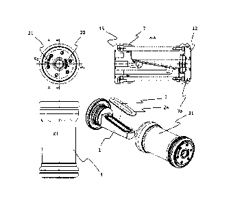
is tracers: by reactions with appropriate non-radioactive precursors,
radiodrugs are synthesized
and, when administered in the human body, permit diagnosis and therapy
monitoring by
Positron Emission Tomography (PET), especially in the treatment of tumors.
Some radiodrugs
can have therapeutic effect as well.
[3] Document EP 1 717 819 discloses a system for automatically producing
radionuclides. In the system disclosed, a cylindrical target carrier, or
capsule, comprising a
partition wall defining two open cylindrical cavities is disclosed. One of the
cylindrical cavities
is used to house the target material for irradiation. In the system disclosed,
the capsule is used
as a shuttle between an irradiation unit where the target material carried by
the capsule is
irradiated, and a hot cell wherein the electrodeposition and the
electrodissolution of the target
material can take take place thanks to an electrolytic cell. A pneumatic
transfer system is
arranged to transfer the capsule between the hot cell and the irradiation
unit. A purifying system
is also present and is used in order to purify the acid solution comprising
the radionuclide
obtained from the electrodissolution step. In this system, the irradiation
takes place in an
irradiation unit which receives a particle beam from a cyclotron. In the case
different
radionuclides need to be produced or when target materials with different
thicknesses are used
in this system, the energy of the particle beam irradiating the target
material needs to be varied.
This can be done by using a more complex accelerator which can deliver a beam
with a variable
energy. When the accelerator can only deliver the particle beam at a fixed
energy, the energy
CA 3049556 2019-07-15
2
T0220-EP-P
of the beam irradiating the target material can still be varied by using a
degrader foil
positioned across the beamline in the irradiating unit. By switching between
different
degrader foils, the energy of the beam obtained from a fixed energy cyclotron
can
consequently be tuned such to irradiate the target material with the
appropriate energy level.
Switching between different degrader foils is however an awkward procedure
which involves
a shutting down of the system, with obvious adverse economic implications, and
an access to
the irradiation station, generating a radiation exposure of the maintenance
staff.
Summary of the invention
[4]
It is an object of the present invention to provide a system for
automatically
producing radionuclides with an increased flexibility for varying the energy
of the beam
irradiating the target material.
151
The present invention is defined in the appended independent claims.
Preferred
embodiments are defined in the dependent claims.
[6]
In particular, the invention concerns a capsule for the transfer of a target
material in
a conveying system between a target irradiation station and a collecting
station, such as a hot
cell, comprising:
- a beamline channel extending along a beamline channel axis for the passage
of an
energetic beam irradiating said target material,
-
a target holder for holding the target material or a substrate backing the
target material
at a glancing angle with respect to said beamline channel axis,
- a housing for enclosing said target holder, said housing being openable such
that the
target material can be inserted in or removed from the target holder when the
housing
is opened,
- a degrader foil, said degrader foil being positioned across the beamline
channel, for
degrading the energy of said energetic beam upstream of the target material,
- at least one target cooling inlet and one target cooling outlet for the
passage of a
cooling fluid in a cooling duct in the vicinity of the target holder such that
the target
material can be cooled during the irradiation,
- at least one degrader foil cooling inlet and one degrader foil cooling
outlet for the
passage of a cooling gas in the vicinity of said degrader foil.
CA 3049556 2020-01-31
3
T0220-EP-P
[7] In an advangeous embodiment, the glancing angle is comprised between
100 and
90 .
[8] In an advangeous embodiment, the capsule has a shape defined by a
geometry of
revolution around said beamline channel axis, said capsule comprising a front
end and a back
end, the beamline channel extending inside the capsule from said front end to
said target
holder.
191
In an advangeous embodiment, the target cooling inlet is located in the back
end of
said capsule, said target cooling inlet being aligned with the beamline
channel axis.
[10] In an advangeous embodiment, the target cooling outlet is located in
the back end
of said capsule, said target cooling outlet being an annular cooling outlet
located around the
beamline channel axis.
[11] In an advangeous embodiment, the housing comprises a closing lid,
wherein
- said closing lid is coaxially fastenable to said housing with respect to
said beamline
axis such to form the back end of said capsule,
- said target holder is rigidly coupled to said closing lid such that said
target holder is
inserted into said housing when said closing lid is fastened to said housing.
[12] In an advantageous embodiment, the target cooling duct is configured
such that the
cooling fluid can contact the target material or the substrate backing the
target material held in
the target holder.
[13] The invention also concerns a system for the irradiation of a target
material in a
target irradiation station and the transfer of the irradiated target material
between said target
irradiation station and a collecting facility, such as a hot cell, comprising:
- at least one capsule as discussed supra,
- a receiving station for being located in said collecting facility,
- a target irradiation station for receiving an energetic beam from a beamline
along a
beamline axis,
- a conveying system comprising a transfer tube for conveying said capsule
between
said receiving station and said target irradiation station,
CA 3049556 2020-01-31
4
T0220-EP-P
wherein
- said conveying system comprises a first terminal located in said target
irradiation
station,
- said
target irradiation station comprises an irradiation unit for the irradiation
of said
target material,
- said irradiation station comprises a first actuator for the transfer of the
capsule
between the first terminal and the irradiation unit and a second actuator for
the locking
of the capsule in an irradiation position,
- said target irradiation station comprises a collimator for narrowing the
energetic beam
from the beamline,
- said at least one capsule can be locked in the irradiation unit by
the second actuator in
an irradiation position wherein the beamline channel axis of said capsule is
aligned
and connected with said beamline,
- said target irradiation station comprises at least one target cooling inlet
duct and one
target cooling outlet duct being in fluid communication with the target
cooling inlet
and the target cooling outlet of said capsule when said capsule is locked in
its
irradiation position,
- said target irradiation station comprises at least one degrader foil cooling
inlet duct
and one degrader foil cooling outlet duct being in fluid communication with
the
degrader foil cooling inlet and the degrader foil cooling outlet of said
capsule when
said capsule is locked in its irradiation position,
- said receiving station is connected to the transfer tube as a second
terminal of said
conveying system, said receiving station being openable such that said capsule
can be
extracted from said receiving station.
[14] In an advantageous embodiment, the conveying system is a pneumatic
system.
[15] In an advantageous embodiment, the conveying system is a vacuum
pneumatic
system.
[16] In an advantageous embodiment, the receiving station is connected to
the transfer
tube through a gate valve such that the second terminal can be used as an
airlock between said
conveying system and said collecting facility.
CA 3049556 2020-01-31
T0220-EP-P
[17] In an advantageous embodiment, the target cooling inlet duct and the
target cooling
outlet duct of said irradiation station, as well as the target cooling inlet
and the target cooling
outlet of said capsule, are configured such that the target cooling inlet duct
of said irradiation
station is in fluid communication with the target cooling inlet of said
capsule and such that the
5
target cooling outlet duct of said irradiation station is in fluid
communication with the target
cooling outlet of said capsule irrespective of the relative angular
orientation between said
capsule and said irradiation unit with respect to the beamline channel axis
when said capsule
is locked in the irradiation position.
[18] In an advantageous embodiment,
- the target cooling inlet of said capsule is a circular inlet located in the
back end of said
capsule, said target cooling inlet being aligned with the beamline channel
axis,
- the target cooling outlet of said capsule is located in the back end
of said capsule, said
target cooling outlet being an annular cooling outlet located around the
beamline
channel axis,
- the target cooling inlet duct of said irradiation station has an end portion
located on the
beamline axis with a circular shape having a radius matching the radius of the
target
cooling inlet of said capsule,
- the target cooling outlet duct of said irradiation station has an end
portion located on
the beamline axis with an annular outlet having a radius matching the radius
of the
target cooling outlet of said capsule.
[19] In an advantageous embodiment, the degrader foil cooling inlet duct
and the
degrader foil cooling outlet duct of said irradiation station, as well as the
degrader foil cooling
inlet and the degrader foil cooling outlet of said capsule, are configured
such that the degrader
foil cooling inlet duct of said irradiation station is in fluid communication
with the degrader
foil cooling inlet of said capsule and such that the at least one degrader
foil cooling outlet duct
of said irradiation station is in fluid communication with the degrader foil
cooling outlet of
said capsule irrespective of the relative angular orientation between said
capsule and said
irradiation unit with respect to the beamline channel axis when said capsule
is locked in the
irradiation position.
[20] In an advantageous embodiment,
CA 3049556 2020-01-31
6
T0220-EP-P
- the degrader foil cooling inlet of said capsule is an arc shaped inlet with
a radius
located in the front end of said capsule,
- the
degrader foil cooling outlet of said capsule is an arc shaped outlet located
in the
front end of said capsule, said arc shaped outlet having a radius different
from the
radius,
- the
degrader foil cooling inlet duct of said irradiation station has an end
portion with
an annular shape around the beamline axis having a radius matching the radius
of the
arc shaped inlet of said capsule,
- the
degrader foil cooling outlet duct of said irradiation station has an end
portion with
an annular shape around the beamline axis having a radius matching the radius
of the
arc shaped outlet of said capsule.
Brief description of the drawings
[21] These
and further aspects of the invention will be explained in greater detail by
way
of example and with reference to the accompanying drawings in which:
Figure 1 shows a capsule for a system according to the present invention;
Figure 2 is an enlarged sectional view of the capsule according to Figure 1;
Figure 3 is a schematic view of a system according to the present invention;
Figure 4 shows the irradiation station of a system according to the present
invention;
Figure 5 shows a sectional view of the irradiation station according to Figure
4, with a
capsule locked in its irradiation position;
Figure 6 is a detailed view of a part of a system according to the invention
connected to
the beamline of an energetic beam generator;
The figures are not drawn to scale.
Detailed description of preferred embodiments
[22] Figures
1 and 2 show an example of a capsule for the transfer of a target material 2
according to the invention, for use in a conveying system between a target
irradiation station
and a collecting station, such as a hot cell.
[23] The capsule comprises:
CA 3049556 2020-01-31
7 T0220-
EP-P
- a
beamline channel 4 extending along a beamline channel axis X1 for the passage
of an
energetic beam irradiating said target material 2,
- a target holder 1 for holding the target material 2 or a substrate 2a
backing the target
material 2 at a glancing angle with respect to said beamline channel axis Xl,
- a housing 3 for
enclosing said target holder 1, said housing 3 being openable such that
the target material 2 can be inserted in or removed from the target holder 1
when the
housing 3 is opened,
- at least one degrader foil 5a, 5b, 5c being positioned across the
beamline channel 4, for
degrading the energy of the energetic beam upstream of the target material 2,
- at least one target cooling inlet 14 and one target cooling outlet 15 for
the passage of a
cooling fluid in a cooling duct 6 in the vicinity of the target holder 1 such
that the target
material 2 can be cooled during the irradiation,
- at least one degrader foil cooling inlet 20 and one degrader foil
cooling outlet 21 for the
passage of a cooling gas in the vicinity of the at least one degrader foil 5a,
5b, Sc.
[24] The energetic beam to be received in the capsule for irradiating the
target material 2
is typically a particle beam, like a proton beam, but can also be an
electromagnetic radiation,
like Gamma ray. Such kinds of energetic beams are indeed commonly used in
applications for
the production of radionuclides by (photo)nuclear reactions wherein the use of
the capsule
according to the invention is highly advantageous.
[25] In Figures 1 and 2, the target material 2 is backed by a substrate 2a.
Such target
material 2 backed by a substrate 2a can be obtained by a chemical process
wherein the target
material 2 is electrodeposited on the substrate 2a. In another embodiment the
target material
can be melted or pressed into an appropriate cavity in the substrate.
Alternatively, when it is
not backed by a substrate, the target material 2 can be directly held by the
target holder 1.
Typical examples of common targets are enriched or natural nickel
electrodeposited on silver
or gold or gold plated copper substrates, enriched or natural thallium on
copper substrate,
enriched or natural zinc on copper or gold plated copper substrate, alloys of
enriched or natural
gallium and nickel on copper or gold plated copper, enriched or natural
antimony on copper or
gold plated copper substrate, enriched or natural tellurium oxide melted into
a cavity in
platinum or iridium substrate, enriched or natural strontium oxide pressed
into a cavity in
platinum or iridium substrate, natural yttrium foil fixed by a fixing ring
into a cavity in platinum
or iridium substrate, sheets or foils of metals without substrate, etc
CA 3049556 2019-07-15
8 T0220-
EP-P
[26] The target holder 1 is configured to receive the target material 2 and
to stabilize it at
a glancing angle with respect to the beamline channel axis X 1 . The glancing
angle is
advantageously comprised in a range between 100 and 90 wherein a glancing
angle of 90
corresponds to a target material 2 perpendicular to the beamline axis X 1 . A
glancing angle
lower than 90 increases the effective thickness of the target material
exposed to the irradiation,
which ultimately allows increasing the yield of the radionuclides production
while keeping
constant the actual thickness of the target material. A glancing angle lower
than 90 also
increases the effective surface area of the target exposed to the beam
reducing the average beam
current density and thereby increasing the beam current acceptance of the
target and
consequently the yield.
[27] In Figures 1 and 2, the capsule has a tubular lateral wall defined by
a geometry of
revolution around the beam line channel axis X1 and is closed by a front end
12 and a back end
13. The housing 3 is a sheath enclosing the different components of the
capsule. The housing
3 has a protective function for the target material 2 and can be made up of
any suitable material,
e.g. aluminium or aluminium alloys, titanium or titanium alloys, niobium or
niobium alloys,
etc.
[28] The housing 3 needs to be openable such that the target material 2 can
be inserted or
removed from the target holder 1 by a human or robotic operator, typically in
a shielded nuclear
radiation containment chamber (the so-called "hot cell"). In this regard, the
housing 3 can
comprise a main body 31 and a closing lid 7. The closing lid 7 is coaxially
fastenable to said
main body 31 with respect to said beamline axis X1 such to form the back end
13 of said
capsule. The target holder 1 is advantageously rigidly coupled to the closing
lid 7 such that
when the closing lid 7 is fastened to the main body 31, the target holder 1 is
inserted into said
main body 1 at the required glancing angle. Alternatively, when the housing
does not comprise
a main body 31 and a closing lid 7, the housing 3 can comprise a slide system
or door such that
the housing is openable and the target material 2 can be accessed.
[29] The at least one degrader foil 5a, 5b, 5c positioned across the
beamline channel 4 of
the capsule allows degrading the energy of the energetic beam received in the
capsule such that
the required energy level is reached when the beam hits the target material 2.
When the beam
delivered to the capsule has a fixed energy, it is indeed necessary to tune
the energy of the beam
downstream of the beam generator. The number, thickness and material of the
degrader foils
that are included in the capsule depend on the beam energy level delivered by
the beam
CA 3049556 2019-07-15
9 T0220-
EP-P
generator and on the required beam energy level to be delivered on the target
material 2. In
Figures 1 and 2, the capsule comprises three degrader foils 5a, 5b, 5c. In
other embodiments,
the capsule can comprise only one or two degrader foils, or alternatively more
than three
degrader foils. In the embodiment of Figures 1 and 2, the degrader foils are
made of aluminium
and have a width of 0.25mm. Any material of any width with a suitable energy
degradation
power can however be used.
[30] The presence of degrader foils in the capsule according to the
invention allows for
the reduction of the ionising radiation dose received by the operators during
the maintenance
of the target station. It is well known that the energy degrader foils are
getting heavily activated
during the operation of the target station, hence they are the strongest
source of ionizing
radiation induced in the target station other than the target and the
substrate. Since the energy
degrader foils are part of the capsule, they are removed from the target
station together with the
irradiated target after every irradiation, hence the only activated parts
remaining in the vicinity
of the target station are the collimators and beam stops along the beamline.
[31] The degrader foils 5a, 5b, 5c can be removably mounted on the capsule
such to be
replaced when necessary. This will allow the degrader foils 5a, 5b, Sc to be
replaced, for
example after a predetermined number of irradiations, or alternatively when a
new target
material 2 requiring a different energy degradation power needs to be
irradiated. The degrader
foils 5a, 5b, Sc can also be mounted on a support 3a being detachable from the
rest of the
housing 3. In such configuration, the degrader foils 5a, 5b, 5c can be changed
by removing the
support 3a and by mounting a new support 3a on the capsule.
[32] The at least one cooling inlet 14 and at least one target cooling
outlet 15 for the
passage of a cooling fluid in a cooling duct 6 in the vicinity of the target
holder 1 can be located
in the back end 13 of said capsule. In Figures 1 and 2, the target cooling
inlet 14 is a circular
outlet aligned with the beamline channel axis Xl, while the target cooling
outlet 15 is an annular
outlet located around the beamline channel axis X 1 . The cooling duct 6 is a
passage in the
capsule connecting the target cooling inlet 14 to the target cooling outlet
15. The function of
the cooling duct 6 is to evacuate the heat generated during the irradiation
from the target
material 2. The cooling duct 6 needs consequently to circulate a cooling
fluid, such as cooling
water, or any other suitable fluid with high boiling point, high heat capacity
and high heat
conductivity near the target material 2. In Figures 1 and 2, the cooling duct
6 is configured to
bring the cooling fluid in contact with the substrate 2a backing the target
material 2. In other
CA 3049556 2019-07-15
T0220-EP-P
embodiments, the cooling duct 6 can be configured such that the cooling fluid
is brought near
the substrate 2a without contacting it. In these embodiments, the cooling duct
6 advantageously
comprises a portion separated from the substrate 2a by a thin layer of
thermally conductive
material.
5 [33] The energetic beam received by the capsule will also generate
a heating of the
degrader foils 5a, 5b, 5c. In order to limit the thermal increase in the
degrader foils, a cooling
fluid can be brought in the vicinity of the at least one degrader foil 5a, 5b,
5c. As represented
in Figures 1 and 2, a degrader foil cooling inlet 20 and a degrader foil
cooling outlet 21 can be
configured to allow the passage of a cooling fluid tangentially to the
degrader foils 5a, 5b, 5c.
10 As it will spread in the beamline channel 4 during the irradiation, the
cooling fluid is
advantageously an inert substance, such as a noble gas. In Figures 1 and 2,
the degrader foil
cooling inlet 20 is an arc shaped inlet with a radius R1 located in the front
end 12 of the capsule.
The degrader foil cooling outlet 21 is an arc shaped outlet also located in
the front end 12 of
said capsule, but with a radius R2 different from Rl.
[34] In the capsule represented in Figures 1 and 2, the degrader foil 5c
and target holder
1 define a closed cavity in said beamline channel 4. In this configuration,
the contamination of
the irradiation station and of the beamline by the cooling fluid circulated in
the beamline
channel 4 is prevented because the cooling fluid does not leak outside of the
closed cavity in
the capsule. In addition, the circulation of the cooling fluid in the beamline
channel 4 can be
forced tangentially to the front face of the target material, which will
enhance the heat removal
from the target, which is particularly important for target materials with low
heat conductivity.
[35] The presence of the degrader foils 5a, 5b, 5c embedded in the capsule
according to
the invention allows tuning the energetic beam upstream of the target material
2 without having
to switch between degrader foils located in the irradiation unit 10. The use
of the capsule
according to the invention in a system for producing radionuclides is
consequently highly
advantageous. Indeed, with the capsule according to the invention, different
target materials 2
requiring different beam energy levels can be irradiated successively without
using a beam
generator with a variable energy level and without accessing the irradiation
station 10.
[36] As represented in Figure 3, the present invention also relates to a
system for the
irradiation of a target material in a target irradiation station 10 and the
transfer of the irradiated
target material between said target irradiation station 10 and a collecting
facility, such as a hot
cell 9, comprising:
CA 3049556 2019-07-15
11 T0220-
EP-P
- at least one capsule as described supra,
- a receiving station 8 for being located in the collecting facility 9,
- a target irradiation station 10, as represented in Figure 4, for
receiving an energetic beam
from a beamline along a beamline axis,
- a conveying system 11 comprising a transfer tube 12 for conveying said
capsule
between said receiving station 8 and said target irradiation station 10,
wherein
- the
conveying system 11 comprises a first terminal 16 located in the target
irradiation
station 10,
- the target irradiation station 10 comprises an irradiation unit 17 for the
irradiation of the
target material 2,
- the irradiation station 10 comprises a first actuator 34 for the transfer of
the capsule
between the first terminal 16 and the irradiation unit 17 and a second
actuator 18 for the
locking of the capsule in an irradiation position,
- the target irradiation station 10 comprises a collimator 19 for narrowing
the energetic
beam from the beamline,
- the at least one capsule can be locked in the irradiation unit 17 by the
second actuator
18 in an irradiation position wherein the beamline channel axis X1 of said
capsule is
aligned and connected with the beamline,
- the target irradiation station 10 comprises a target cooling inlet duct 22
and a target
cooling outlet duct 23 being in fluid communication with the target cooling
inlet 14 and
the target cooling outlet 15 of the capsule when the capsule is locked in its
irradiation
position,
- the target irradiation station 10 comprises a degrader foil cooling inlet
duct 24 and a
degrader foil cooling outlet duct 25 being in fluid communication with the
degrader foil
cooling inlet 20 and the degrader foil cooling outlet 21 of the capsule when
the capsule
is locked in its irradiation position,
- the receiving station 8 is connected to the transfer tube 12 as a second
terminal of the
conveying system 11, the receiving station 8 being openable such that the
capsule can
be extracted from the receiving station 8.
[37] In
the system represented in Figures 3, the conveying system 11 is a vacuum
pneumatic conveying system. Such system comprises a first suction tube 26 in
fluid
CA 3049556 2019-07-15
12 T0220-
EP-P
communication with the transfer tube through the first terminal 16 in the
irradiation station 10.
It also comprises a second suction tube 27 in fluid communication with the
transfer tube 12
through the receiving station 8 ("second terminal"). The suction tubes 26, 27
are connected to
an air blower 28 and to the atmosphere through three-way valves 29 and 30. A
HEPA filter 31
can also be included between the air blower 28 and the three-way valves 29 and
30.
[38] The principle of operation of the conveying system is the
following:
= when the capsule needs to be transferred from the collecting facility 9
to the irradiation
station 10, the atmosphere port of the first three-way valve 29 is closed
while the first
suction tube 26 is set in fluid communication with the blower 28. On the other
hand, the
air blower port of the second three-way valve 30 is closed while the second
suction tube
27 is set in fluid communication with the atmosphere. The air is consequently
sucked
out of the first suction tube 26 through the air blower 28. This depression in
the suction
tube 26 generates a motion of the capsule in the transfer tube 12 from the
collecting
facility 9 to the irradiation station 10 and at the same time an air suction
from the
atmosphere into the second suction tube 27.
= when the capsule needs to be transferred from the irradiation station 10
to the collecting
facility 9, the atmosphere port of the second three-way valve 30 is closed
while the
second suction tube 27 is set in fluid communication with the blower 28. On
the other
hand, the air blower port of the first three-way valve 29 is closed while the
suction tube
26 is set in fluid communication with the atmosphere. The air is consequently
sucked
out of the second suction tube 27 through the air blower 28. This depression
in the
suction tube 27 generates a motion of the capsule in the transfer tube 12 from
the
irradiation station 10 to the collecting facility and at the same time an air
suction from
the atmosphere into the first suction tube 26.
[39] As represented in Figure 3, the system can comprise two additional
valves 32, 33,
such as ball valves, in the collecting facility 9. The first valve 32 is
positioned across the transfer
tube 12 and the second valve 33 is positioned across the second suction tube
27. In this
arrangement, the receiving station 8 becomes consequently an airlock in the
hot cell 9. These
valves 32, 33 are advantageously kept closed when a capsule is extracted or
placed in the
receiving station 8. This operation will ensure that the atmosphere of the hot
cell 9 is not
disturbed by the air used for the transfer of the capsules and that the
potentially contaminated
atmosphere of the hot cell 9 will not enter the air stream of the conveying
system 11. When a
CA 3049556 2019-07-15
13 T0220-
EP-P
capsule needs to be transferred between the hot cell 9 and the irradiation
station 10, the valves
32, 33 are opened such that the conveying system 11 can be operated as
described supra.
[40] An example of an irradiation station 10 of a system according to
invention is
disclosed in more details in Figures 4 and 5. The irradiation station 10 is
mounted on a mounting
stand 35 through a positioning mechanism, which allows for a precise alignment
of the
irradiation unit relative to the beam. Besides the elements already described
supra, the
irradiation station 10 can also comprise a cooling system for the collimator
19. Such cooling
system comprises a collimator cooling inlet duct 36 and a collimator cooling
outlet duct 37.
[41] As represented in Figures 4 and 5, the irradiation station 10
comprises two actuators:
34 and 18 for positioning and locking the capsules. When the capsule is
received in the first
terminal 16 of the irradiation station 10, the first actuator 34 transfers the
capsule to the
irradiation unit 17. By the action of the second actuator 18 the capsule is
locked in its irradiation
position. The irradiation position of the capsule in the irradiation unit 17
is a position of the
capsule wherein
= the beamline channel axis X1 is aligned and connected with the beamline,
= the target cooling inlet duct 22 and the target cooling outlet duct 23
are in fluid
communication with the target cooling inlet 14 and the target cooling outlet
15 of the
capsule,
= the degrader foil cooling inlet duct 24 and the degrader foil cooling
outlet duct 25 are in
fluid communication with the degrader foil cooling inlet 20 and the degrader
foil cooling
outlet 21 of said capsule.
[42] In an
advantageous embodiment of the system, the target cooling inlet duct 22 of the
irradiation station 10 is configured such that it is in fluid communication
with the target cooling
inlet 14 of the capsule irrespective of the relative angular orientation
between the capsule and
the irradiation unit 17 with respect to the beamline channel axis X1 when the
capsule is locked
in the irradiation position. Similarly, the target cooling outlet duct 23 of
the irradiation station
10 is advantageously configured such that it is in fluid communication with
the target cooling
outlet of the capsule irrespective of the relative angular orientation between
the capsule and the
irradiation unit 17 with respect to the beamline channel axis X1 when the
capsule is locked in
the irradiation position. In this configuration, the target cooling system is
operational at any
angular orientation of the capsule in the irradiation unit 10 with respect to
the beamline channel
CA 3049556 2019-07-15
14 T0220-
EP-P
axis X1 . This reduces the task complexity of the actuators 18 and 34, which
does not need to
measure the angular orientation of the capsule in the first terminal 16 and
does not need to rotate
the capsule at a particular angle with respect to the beamline channel axis X1
when locking the
capsule in its irradiation position.
[43] In the capsule represented in Figures 1 and 2, wherein the target
cooling inlet 14 is a
circular inlet located in the back end 13 of the capsule and is aligned with
the beamline channel
axis Xl, the target cooling inlet duct 22 of the irradiation station 10 has an
end portion located
on the beamline axis and with a circular shape having a radius matching the
radius of the circular
target cooling inlet 14 of the capsule. Similarly, as represented in Figures 1
and 2, when the
target cooling outlet 15 of the capsule is an annular outlet in the back end
13 of the capsule and
is located around the beamline channel axis X 1 , the target cooling outlet
duct 23 of the
irradiation station 10 has an end portion with an annular outlet around the
beamline axis and
having a radius matching the radius of the target cooling outlet 15. In this
example of
configuration, the target cooling system is operational irrespective of the
relative angular
orientation between the capsule and the irradiation unit 17 with respect to
the beamline channel
axis X1 when the capsule is locked in the irradiation position.
[44] In an advantageous embodiment of the system, the degrader foil cooling
inlet duct
24 of the irradiation station 10 is configured such that it is in fluid
communication with the
degrader foil cooling inlet 20 of the capsule irrespective of the relative
angular orientation
between the capsule and the irradiation unit 17 with respect to the beamline
channel axis X1
when the capsule is locked in the irradiation position. Similarly, the
degrader foil cooling inlet
duct 25 of the irradiation station 10 is advantageously configured such that
it is in fluid
communication with the degrader foil cooling inlet 21 of the capsule
irrespective of the relative
angular orientation between the capsule and the irradiation unit 17 with
respect to the beamline
channel axis X1 when the capsule is locked in the irradiation position. In
this configuration, the
degrader cooling system is operational at any angular orientation of the
capsule in the irradiation
unit 10 with respect to the beamline channel axis X 1 . This reduces the task
complexity of the
actuators 18 and 34, which does not need to measure the angular orientation of
the capsule in
the first terminal 16 and does not need to rotate the capsule at a particular
angle with respect to
the beamline channel axis X1 when locking the capsule in its irradiation
position.
[45] In the capsule represented in Figures 1 and 2, wherein the degrader
foil cooling inlet
20 is located in the front end 12 of the capsule and is an arc shaped inlet
with a radius R1 around
CA 3049556 2019-07-15
15 T0220-
EP-P
the beamline channel axis Xl, the degrader foil cooling inlet duct 24 of the
irradiation station
has an end portion with an annular shape around the beamline axis and having a
radius
matching the radius R I of the arc shaped inlet 20 of the capsule. Similarly,
as represented in
Figures 1 and 2, when the degrader foil cooling outlet 21 is located in the
front end 12 of the
5 capsule and is an arc shaped outlet 21 having a radius R2 around the
beamline channel axis X1
different from the radius R 1 , the degrader foil cooling outlet duct 25 of
the irradiation station
10 has an end portion with an annular shape around the beamline axis and
having a radius
matching the radius R2 of the degrader foil cooling outlet 21.
[46] Figure 6 represents a detailed view of a part of a system
according to the invention
10 connected to the beamline 38 of an energetic beam generator 39. The
energetic beam generator
39 can be a particle accelerator such as a cyclotron. Alternatively, the
energetic beam generator
can generate electromagnetic radiation, like Gamma ray.
CA 3049556 2019-07-15