Language selection

Search

Patent 3049925 Summary

Third-party information liability

Some of the information on this Web page has been provided by external sources. The Government of Canada is not responsible for the accuracy, reliability or currency of the information supplied by external sources. Users wishing to rely upon this information should consult directly with the source of the information. Content provided by external sources is not subject to official languages, privacy and accessibility requirements.

Claims and Abstract availability

Any discrepancies in the text and image of the Claims and Abstract are due to differing posting times. Text of the Claims and Abstract are posted:

  • At the time the application is open to public inspection;
  • At the time of issue of the patent (grant).
(12) Patent: (11) CA 3049925
(54) English Title: PRODUCTION SYSTEM FOR SPECTACLE LENSES
(54) French Title: SYSTEME DE PRODUCTION DE VERRES DE LUNETTES
Status: Granted
Bibliographic Data
(51) International Patent Classification (IPC):
  • B65G 37/02 (2006.01)
  • B24B 13/00 (2006.01)
  • B24B 27/00 (2006.01)
  • B65G 29/00 (2006.01)
  • B65G 35/06 (2006.01)
  • B65G 47/53 (2006.01)
(72) Inventors :
  • MESCHENMOSER, RALF (Germany)
  • SCHULZ, ARNE (Germany)
  • KLORA, DENNIS (Germany)
(73) Owners :
  • CARL ZEISS VISION INTERNATIONAL GMBH (Germany)
(71) Applicants :
  • CARL ZEISS VISION INTERNATIONAL GMBH (Germany)
(74) Agent: PERRY + CURRIER
(74) Associate agent:
(45) Issued: 2020-10-20
(86) PCT Filing Date: 2017-12-08
(87) Open to Public Inspection: 2018-06-28
Examination requested: 2019-07-11
Availability of licence: N/A
(25) Language of filing: English

Patent Cooperation Treaty (PCT): Yes
(86) PCT Filing Number: PCT/EP2017/081972
(87) International Publication Number: WO2018/114386
(85) National Entry: 2019-07-11

(30) Application Priority Data:
Application No. Country/Territory Date
16205102.3 European Patent Office (EPO) 2016-12-19

Abstracts

English Abstract


The invention relates to a production system (100) for spectacle lenses made
from spectacle lens
blanks, comprising a left-hand outer transport track (101), multiple left-hand
processing devices
(121, 123, 125, 127, 129, 131, 133, 135, 137, 139) which are arranged on the
left-hand side next
to the left-hand outer transport track (101), a right-hand outer transport
track (103), and a central
transport track (102) which is arranged between the left-hand outer transport
track (101) and the
right-hand outer transport track (103), wherein the transport direction (101a)
of the left-hand
outer transport hack (101) and the transport direction (103a) of the right-
hand outer transport
track (103) ale identical, and the transport direction (102a) of the central
transport track (102) is
opposite to the transport directions (101a, 103a) of the left-hand outer
transport track (101) and
the right-hand outer transport track (103) or can be reversed. The invention
is characterized in
that multiple right-hand processing devices (122, 124, 126, 128, 130, 132,
134, 136, 138) are
arranged on the right-hand side next to the right-hand outer transport track
(103). A processing
device pan (121, 122; 123, 124, 125, 126;, 135, 136; 137. 138) made of left-
hand and right-hand
processing devices is paired with a transfer device (141, 142, 143,... 146.
147, 148. 149).
which comprises multiple rotational/transport devices (144a, 144b, 144c....
144i, 144j, 144k.
144l and l 44Za. 144Zb, 144Zc. 144Zd) Each transport track (102, 103, 104)
comprises four
respective rotational/transport devices (144a, 144b, 144e. . 144i, 144j. 144k,
144l and 144Za,
144Zb, 144Zc. 144Zd)


French Abstract

L'invention concerne un système de production (100) de verres de lunettes à partir d'ébauches de verre de lunettes, comportant une piste de transport extérieure gauche (101), plusieurs dispositifs de traitement gauches (121, 123, 125, 127, 129, 131, 133, 135, 137, 139) disposés côté gauche à proximité de la piste de transport extérieure gauche (101), une piste de transport extérieure droite (103), une piste de transport médiane (102) disposée entre la piste de transport extérieure gauche (101) et la piste de transport extérieure droite (103), le sens de transport (101a) de la piste de transport extérieure gauche (101) et le sens de transport (103a) de la piste de transport extérieure droite (103) sont identiques, et le sens de transport (102a) de la piste de transport médiane (102) est située à l'opposé du sens de transport (101a, 103a) de la piste de transport extérieure gauche (101) et la piste de transport droite (103) ou peut être inversée. L'invention se caractérise en ce que plusieurs dispositifs de traitement droits (122, 124, 126, 128, 130, 132, 134, 136, 138) sont disposés à proximité de la piste de transport extéreure droite (103). Un dispositif de transfert (141, 142, 143,... 146, 147, 148, 149) est associé à une paire de dispositifs de traitement (121, 122; 123, 124; 125, 126;.. 135, 136; 137, 138) les dites paires étant composées respectivement de dispositifs de traitement gauches et droits, le dispositif de transfert comprenant plusieurs dispositifs de rotation et de transport (144a, 144b, 144c,... 144i, 144j, 144k, 144l et 144Za, 144Zb, 144Zc, 144Zd). Chaque piste de transport (102, 103, 104) comprend respectivement quatre dispositifs de rotation et de transport (144a, 144b, 144c,... 144i, 144j, 144k, 144l et 144Za, 144Zb, 144Zc, 144Zd).

Claims

Note: Claims are shown in the official language in which they were submitted.


33

claims:

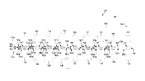
1. A system (100) for producing spectacle lenses from spectacle lens blanks,
comprising
- an outer left transport track (101) for transporting the spectacle lens
blanks in a transport
direction (101a),
- a plurality of left process devices (121, 123, 125, 127, 129, 131, 133,
135, 137, 139) for the
spectacle lens blanks, said left process devices (121, 123, 125, 127, 129,
131, 133, 135,
137, 139) being arranged to the left of the outer left transport track (101)
and being
configured to carry out at least one process step on the respective spectacle
lens blank in
order to convert the latter into the final spectacle lens blank or finished
spectacle lens,
- an outer right transport track (103) for transporting the spectacle lens
blanks in a transport
direction (103a),
- a central transport track (102) arranged between the outer left transport
track (101) and the
outer right transport track (103), for transporting the spectacle lens blanks
in a transport
direction (102a), wherein
- the transport direction (101a) of the outer left transport track (101) and
the transport
direction (103a) of the outer right transport track (103) are identical,
wherein
- the transport direction (102a) of the central transport track (102) is
counter to the transport
directions (101a, 103a) of the outer left transport track (101) and the outer
right transport
track (103) or reversible,
characterized in that
- a plurality of right process devices (122, 124, 126, 128, 130, 132, 134,
136, 138) for the
spectacle lens blanks are present, arranged to the right of the outer right
transport track
(103), said right process devices (122, 124, 126, 128, 130, 132, 134, 136,
138) being
configured to carry out at least one process step on the respective spectacle
lens blank in
order to convert the latter into the final spectacle lens blank or finished
spectacle lens,
wherein
- in pairs, one or more of the right process devices (122, 124, 126, 128,
130, 132, 134, 136,
138) are arranged lying opposite one or more of the left process devices (121,
123, 125,
127, 129, 131, 133, 135, 137, 139) in relation to the left, right and central
transport tracks
(101, 102, 103), forming one or more process device pairs (121, 122; 123, 124;
125, 126;
... 135, 136; 137, 138), wherein
- one or more of the process device pairs (121, 122; 123, 124; 125, 126; ...
135, 136; 137,
138) each have a transfer device (141, 142, 143, ... 146, 147, 148, 149),
respectively

34
assigned to a process device pair (121, 122; 123, 124; 125, 126; ... 135, 136;
137, 138), for
transferring the spectacle lens blanks between a respective left process
device (121, 123,
125, 127, 129, 131, 133, 135, 137, 139) of the respective process device pair
(121, 122;
123, 124; 125, 126; ... 135, 136; 137, 138) and the outer left transport track
(101) and the
central transport track (102) and for transferring the spectacle lens blanks
between a
respective right process device (122, 124, 126, 128, 130, 132, 134, 136, 138)
of the
respective process device pair (121, 122; 123, 124; 125, 126; ... 135, 136;
137, 138) and
the outer right transport track (103) and the central transport track (102),
and
- at least one of the transfer devices (141, 142, 143, ... 146, 147, 148, 149)
comprises a
plurality of rotation/transport devices (144a, 144b, 144c, , 144i, 144j, 144k,
1441 and
144Za, 144Zb, 144Ze, 1442d), wherein
(i) the outer left transport track (101) comprises four outer left
rotation/transport devices
(144a. 144b, 144c, 144d) of the plurality of rotation/transport devices (144a.
144b, 144c,
... 144i, 144j, 144k, 1441 and 144Za, 144Zb, I 44Ze, 144Zd),
(ii) the central transport track (102) comprises four central
rotation/transport devices (144e,
144f, 144g, 144h) of the plurality of rotation/transport devices (144a, 144b,
144c, ... I 44i,
144j 144k, 1441 and I 44Za, 144Zb, 144Zc, 144Zd),
(iii) the outer right transport track (103) comprises four outer right
rotation/transport devices
(144i, 144j, 144k, 1441) of the plurality of rotation/transport devices (144a,
144b, 144c, ...
144i, 144j 144k, 1441 and 144Za, 144Zb, 144Zc, 144Zd).
2. The production system (100) as claimed in claim 1, characterized in that
- the four outer left rotation/transport devices (144a, 144b, 144c, 144d) and
the four central
rotation/transport devices (144e, 144f, 144g, 144h) and the four outer right
rotation/transport
devices (144i, 144j, I44k, 1441) are arranged to form a 3 x 4 matrix.
3. The production system (100) as claimed in claim 1 or 2, characterized in
that
- two further left rotation/transport devices (171a, 171b) of the plurality of
rotation/transport
devices (144a, 144b, 144c, ... 144i, 144j 144k, 1441 and 144Za, 144Zb, 144Ze,
144Zd) are
arranged to the left-hand side of the four outer left rotation/transport
devices (144a, 144b,
144c, I44d) and/or in that
- two further right rotation/transport devices (172a, 172b) of the plurality
of rotation/transport
devices (144a, 144b, 144c, ... 144i, 144j 144k, 1441 and 144Za, 144Zb, 144Zc,
144Zd) are

35
arranged to the right-hand side of the four outer right rotation/transport
devices (144i, 144j,
144k, 1441).
4. The production system (l 00) as claimed in any one of claims 1 - 3,
characterized in that
- a left central transport track (101Z) is present, arranged between the outer
left transport track
(101) and the central transport track (102), for transporting the spectacle
lens blanks in a
transport direction (10IZa, 101Zb), and/or
- a right central transport track (103Z) is present, arranged between the
outer right transport
track (103) and the central transport track (102), for transporting the
spectacle lens blanks in
a transport direction (103Za, 103Zb).
5. The production system (100) as claimed in claim 4, characterized in that
(i) the left central transport track (101Z) comprises four left central
rotation/transport
devices (144Za, 144Zb, 144Zc, 144Zd) of the plurality of rotation/transport
devices (144a,
144b, 144c,...144i, 144j, 144k, 1441 and 144Za, 144Zb, 144a, 144Zd),
(i) the right central transport track (I03Z) comprises four right central
rotation/transport
devices (144Ze, 144Zf, 144Zg, 144Zh) of the plurality of rotation/transport
devices (144a,
144b, 144c, ... 144i, 144j, I44k, 144I and 144Za, 144Zb, 144Zc, 144Zd),
6. The production system (100) as claimed in either of claims 4 and 5,
characterized in that the
plurality of rotation/transport devices (144a, 144b, 144c, ... 144i, 144j
144k, 1441 and 144Za,
144Zb, 144Zc, 144Zd) are rotatable in 45° steps.
7. The production system (100) as claimed in any one of claims 4 - 6,
characterized in that
- the transport direction (101Za, 101Zb) of the left central transport track
(101Z) is reversible
and/or
- the transport direction (103Za, 103Zb) of the right central transport
track (103Z) is
reversible.
8. The production system (100) as claimed in any one of claims 1 - 7,
characterized in that
- the transport direction (101a) of the outer left transport track (101) is
not reversible and/or
- the transport direction (I03a) of the outer right transport track (103) is
not reversible and/or
- the transport direction (102a) of the central transport track (102) is not
reversible.

36
9. The production system (100) as claimed in any one of claims 1 - 8,
characterized in that
- the outer left transport track (101) has one or more outer left transport
devices (161a, 161b,
... 161i), which is/are driven for transporting the spectacle lens blanks in
the transport
direction (101a) of the outer left transport track (101),
- the outer right transport track (103) has one or more outer right transport
devices (163a,
163b, ... 163i), which is/are driven for transporting the spectacle lens
blanks in the transport
direction (103a) of the outer right transport track (103),
- the central transport track (102) has one or more transport devices
(162a, 162b, ... 162i),
which is/are driven for transporting the spectacle lens blanks in the
transport direction
(102a) of the central transport track (102),
10. The production system (100) as claimed in any one of claims 1 - 9,
characterized in that
- a computing device (180) is present, wherein
(i) the computing device (180) is configured to calculate a fastest transport
path for
transporting a predetermined spectacle lens blank of the spectacle lens blanks
to a
predetermined process device (121, 122; 123, 124; 125, 126; ... 135, 136; 137,
138) of the
process devices (121, 122; 123, 124; 125, 126; ... 135, 136; 137, 138) and/or
(ii) the computing device (180) is configured to calculate a shortest
transport path for
transporting a predetermined spectacle lens blank of the spectacle lens blanks
to a
predetermined process device (121, 122; 123, 124; 125, 126; ... 135, 136; 137,
138) of the
process devices (121, 122; 123, 124; 125, 126; ... 135, 136; 137, 138) and
- a control device (182) is present in order to transport the predetermined
spectacle lens blank
on the calculated transport path.
11. A method for operating a system (100) for producing spectacle lenses from
spectacle lens
blanks, which comprises
- an outer left transport track (101) for transporting the spectacle lens
blanks in a transport
direction (101a),
- a plurality of left process devices (121, 123, 125, 127, 129, 131, 133, 135,
137, 139) for the
spectacle lens blanks, said left process devices (121, 123, 125, 127, 129,
131, 133, 135,
137, 139) being arranged to the left of the outer left transport track (101)
and being
configured to carry out at least one process step on the respective spectacle
lens blank in
order to convert the latter into the final spectacle lens blank or finished
spectacle lens,

37
- an outer right transport track (103) for transporting the spectacle lens
blanks in a transport
direction (103a) and
- a central transport track (102) arranged between the outer left transport
track (101) and the
outer right transport track (103), for transporting the spectacle lens blanks
in a transport
direction (102a), wherein
- the spectacle lens blanks are transported to one or more of the left
process devices (121,
123, 125, 127, 129, 131, 133, 135, 137, 139) via the outer left transport
track (101) and/or
the outer right transport track (103) and/or the central transport track
(102),
- the spectacle lens blanks are transported with an identical transport
direction (101a, 103a)
on the outer left transport track (101) and the outer right transport truck
(103),
- the spectacle lens blanks on the central transport track (102) are
transported in the opposite
or in the same transport direction (101a, 102a, 103a) to the spectacle lenses
on the outer
left transport track (101) and the spectacle lenses on the outer right
transport track (103),
characterized in that the production system (100)
- comprises a plurality of right process devices (122, 124, 126, 128, 130,
132, 134, 136, 138)
for the spectacle lens blanks, said right process devices (122, 124, 126, 128,
130, 132, 134,
136, 138) being arranged to the right of the outer right transport track (103)
and being
configured to carry out at least one process step on the respective spectacle
lens blank in
order to convert the latter into the final spectacle lens blank or finished
spectacle lens,
wherein
- in pairs, one or more of the right process devices (122, 124, 126, 128,
130, 132, 134, 136,
138) are arranged lying opposite one or more of the left process devices (121,
123, 125,
127, 129, 131, 133, 135, 137, 139) in relation to the left, right and central
transport tracks
(101, 102, 103), forming one or more process device pairs (121, 122; 123, 124;
125, 126;
... 135, 136; 137, 138), wherein
- one or more of the process device pairs (121, 122; 123, 124; 125, 126;
... 135, 136; 137,
138) each have a transfer device (141, 142, 143, ... 146, 147, 148, 149),
respectively
assigned to a process device pair (121, 122; 123, 124; 125, 126; ... 135, 136;
137, 138), for
transferring the spectacle lens blanks between a respective left process
device (121, 123,
125, 127, 129, 131, 133, 135, 137, 139) of the respective process device pair
(121, 122;
123, 124; 125, 126; _135, 136; 137, 138) and the outer left transport track
(101) and the
central transport track (102) and for transferring the spectacle lens blanks
between a
respective right process device (122, 124, 126, 128, 130, 132, 134, 136, 138)
of the

38
respective process device pair (121, 122; 123, 124; 125, 126; ... 135, 136;
137, 138) and
the outer right transport track (103) and the central transport track (102),
and
- at least one of the transfer devices (141, 142, 143, ... 146, 147, 148,
149) comprises a
plurality of rotation/transport devices (144a, 144b, 144c, ... 144i, 144j,
144k, 144l and
144Za, 144Zb, 144Zc, 144Zd), wherein
(i) the outer left transport track (101) comprises four outer left
rotation/transport devices
(144a, 144b, 144c, 144d) of the plurality of rotation/transport devices (144a,
144b, 144c,
... 144i, 144j, 144k, 144l and 144Za, 144Zb, 144Zc, 144Zd),
(ii) the central transport track (102) comprises four central
rotation/transport devices (144e,
144f, 144g, 144h) of the plurality of rotation/transport devices (144a, 144b,
144c, ... 144i,
144j 144k, 144l and 144Za, 144Zb, 144Zc, 144Zd),
(iii) the outer right transport track (103) comprises four outer right
rotation/transport devices
(144i, 144j, 144k, 144l) of the plurality of rotation/transport devices (144a,
144b, 144c, ...
144i, 144j 144k, 144l and 1442a, 1442b, 1442c, 1442d), wherein
- the spectacle lens blanks are transported to one or more of the plurality
of right process
devices (122, 124, 126, 128, 130, 132, 134, 136, 138), arranged to the right
side of the
outer right transport track (103), for the spectacle lens blanks via the outer
left transport
track (101) and/or the outer right transport track (103) and/or the central
transport track
(102).
12. A system (100) for producing spectacle lenses from spectacle lens blanks,
comprising
- an outer left transport track (101) for transporting the spectacle lens
blanks in a transport
direction (101a),
- a plurality of left process devices (121, 123, 125, 127, 129, 131, 133, 135,
137, 139) for the
spectacle lens blanks, said left process devices (121, 123, 125, 127, 129,
131, 133, 135,
137, 139) being arranged to the left of the outer left transport track (101)
and being
configured to carry out at least one process step on the respective spectacle
lens blank in
order to convert the latter into the final spectacle lens blank or finished
spectacle lens,
- an outer right transport track (103) for transporting the spectacle lens
blanks in a transport
direction (103a),
- a central transport track (102) arranged between the outer left transport
track (101) and the
outer right transport track (103), for transporting the spectacle lens blanks
in a transport
direction (102a), wherein

39
- the transport direction (101a) of the outer left transport track (101) and
the transport
direction (103a) of the outer right transport track (103) are identical,
wherein
- the transport direction (102a) of the central transport track (102) is
counter to the transport
directions (101a, 103a) of the outer left transport track (101) and the outer
right transport
track (103) or reversible,
characterized in that
- a plurality of right process devices (122, 124, 126, 128, 130, 132, 134,
136, 138) for the
spectacle lens blanks are present, arranged to the right of the outer right
transport track
(103), said right process devices (122, 124, 126, 128, 130, 132, 134, 136,
138) being
configured to carry out at least one process step on the respective spectacle
lens blank in
order to convert the latter into the final spectacle lens blank or finished
spectacle lens,
wherein
- in pairs, one or more of the right process devices (122, 124, 126, 128,
130. 132, 134, 136,
138) are arranged lying opposite one or more of the left process devices (121,
123, 125,
127, 129, 131, 133, 135, 137, 139) in relation to the left, right and central
transport tracks
(101, 102, 103), forming one or more process device pairs (121, 122; 123, 124;
125, 126;
... 135, 136; 137, 138), wherein
- one or more of the process device pairs (121, 122; 123, 124; 125, 126;
... 135, 136; 137,
138) each have a transfer device (141, 142, 143, ... 146, 147, 148, 149),
respectively
assigned to a process device pair (121, 122; 123, 124; 125, 126; ... 135, 136;
137, 138), for
transferring the spectacle lens blanks between a respective left process
device (121, 123,
125, 127, 129, 131, 133, 135, 137, 139) of the respective process device pair
(121, 122;
123, 124; 125, 126; ...135, 136; 137, 138) and the outer left transport track
(101) and the
central transport track (102) and for transferring the spectacle lens blanks
between a
respective right process device (122, 124, 126, 128, 130, 132, 134, 136, 138)
of the
respective process device pair (121, 122; 123, 124; 125, 126; ... 135, 136;
137, 138) and
the outer right transport track (103) and the central transport track (102),
and
- at least one of the transfer devices (141, 142, 143, ... 146, 147, 148, 149)
comprises a
plurality of rotation/transport devices (144a, 144b, 144c, ... 144i, 144j,
144k, 144l and
144Za, 144Zb, 144Zc, 144Zd), wherein each rotation/transport device (144a,
144b, 144c,
... 144i, 144j 144k, 144l and 144Za, 144Zb, 144Zc, 144Zd) has a dedicated
transport drive
and a dedicated rotation drive, wherein

40
(i) the outer left transport track (101) comprises four outer left
rotation/transport devices
(144a, 144b, 144c, 144d) of the plurality of rotation/transport devices (144a,
144b, 144c,
... 144i, 144j, 144k, 144l and 144Za, 144Zb, 144Zc, 144Zd),
(ii) the central transport track (102) comprises four central
rotation/transport devices (144e,
144f, 144g, 144h) of the plurality of rotation/transport devices (144a, 144b,
144c, ... 144i,
144j 144k, 144l and 144Za, 144Zb, 144Zc, 144Zd),
(iii) the outer right transport track (103) comprises four outer right
rotation/transport devices
(144i, 144j, 144k, 144l) of the plurality of rotation/transport devices (144a,
144b, 144c, ...
144i, 144j 144k, 144l and 144Za, 144Zb, 144Zc,144Zd).
13. A method for operating a system (100) for producing spectacle lenses from
spectacle lens
blanks, which comprises
- an outer left transport track (101) for transporting the spectacle lens
blanks in a transport
direction (101a),
- a plurality of left process devices (121, 123, 125, 127, 129, 131, 133,
135, 137, 139) for the
spectacle lens blanks, said left process devices (121, 123, 125, 127, 129,
131, 133, 135,
137, 139) being arranged to the left of the outer left transport track (101)
and being
configured to carry out at least one process step on the respective spectacle
lens blank in
order to convert the latter into the final spectacle lens blank or finished
spectacle lens,
- an outer right transport track (103) for transporting the spectacle lens
blanks in a transport
direction (103a) and
- a central transport track (102) arranged between the outer left transport
track (101) and the
outer right transport track (103), for transporting the spectacle lens blanks
in a transport
direction (102a), wherein
- the spectacle lens blanks are transported to one or more of the left process
devices (121,
123, 125, 127, 129, 131, 133, 135, 137, 139) via the outer left transport
track (101) and/or
the outer right transport track (103) and/or the central transport track
(102),
- the spectacle lens blanks are transported with an identical transport
direction (101a, 103a)
on the outer left transport track (101) and the outer right transport truck
(103),
- the spectacle lens blanks on the central transport track (102) are
transported in the opposite
or in the same transport direction (101a, 102a, 103a) to the spectacle lenses
on the outer
left transport track (101) and the spectacle lenses on the outer right
transport track (103),
characterized in that the production system (100)

41
comprises a plurality of right process devices (122, 124, 126, 128, 130, 132,
134, 136, 138)
for the spectacle lens blanks, said right process devices (122, 124, 126, 128,
130, 132, 134,
136, 138) being arranged to the right of the outer right transport track (103)
and being
configured to carry out at least one process step on the respective spectacle
lens blank in
order to convert the latter into the final spectacle lens blank or finished
spectacle lens,
wherein
- in pairs, one or more of the right process devices (122, 124, 126, 128, 130,
132, 134, 136,
138) are arranged lying opposite one or more of the left process devices (121,
123, 125,
127, 129, 131, 133, 135, 137, 139) in relation to the left, right and central
transport tracks
(101, 102, 103), forming one or more process device pairs (121, 122; 123, 124;
125, 126;
... 135, 136; 137, 138), wherein
- one or more of the process device pairs (121, 122; 123, 124; 125, 126; ...
135, 136; 137,
138) each have a transfer device (141, 142, 143, ... 146, 147, 148, 149),
respectively
assigned to a process device pair (121, 122; 123, 124; 125, 126; ... 135, 136;
137, 138), for
transferring the spectacle lens blanks between a respective left process
device (121, 123,
125, 127, 129, 131, 133, 135, 137, 139) of the respective process device pair
(121, 122;
123, 124; 125, 126; ...135, 136; 137, 138) and the outer left transport track
(101) and the
central transport track (102) and for transferring the spectacle lens blanks
between a
respective right process device (122, 124, 126, 128, 130, 132, 134, 136, 138)
of the
respective process device pair (121, 122; 123, 124; 125, 126; ... 135, 136;
137, 138) and
the outer right transport track (103) and the central transport track (102),
and
- at least one of the transfer devices (141, 142, 143, ... 146, 147, 148, 149)
comprises a
plurality of rotation/transport devices (144a, 144b, 144c, ... 144i, 144j,
144k, 144l and
144Za, 144Zb, 144Zc, 144Zd), wherein each rotation/transport device (144a,
144b, 144c,
... 144i, 144j 144k, 144l and 144Za, 144Zb, 144Zc, 144Zd) has a dedicated
transport drive
and a dedicated rotation drive, wherein
(i) the outer left transport track (101) comprises four outer left
rotation/transport devices
(144a, 144b, 144c, 144d) of the plurality of rotation/transport devices (144a,
144b, 144c,
... 144i, 144j, 144k, 144l and 144Za, 144Zb, 144Zc, 144Zd),
(ii) the central transport track (102) comprises four central
rotation/transport devices (144e,
144f, 144g, 144h) of the plurality of rotation/transport devices (144a, 144b,
144c, ... 144i,
144j 144k, 144l and 144Za, 144Zb, 144Zc, 144Zd),
(iii) the outer right transport track (103) comprises four outer right
rotation/transport devices

42
(144i, 144j, 144k, 144l) of the plurality of rotation/transport devices (144a,
144b, 144c, ...
144i, 144j 144k, 144l and 144Za, 144Zb, 144Zc, 144Zd), wherein
- the spectacle lens blanks are transported to one or more of the plurality of
right process
devices (122, 124, 126, 128, 130, 132, 134, 136, 138), arranged to the right
side of the
outer right transport track (103), for the spectacle lens blanks via the outer
left transport
track (101) and/or the outer right transport track (103) and/or the central
transport track
(102).

Description

Note: Descriptions are shown in the official language in which they were submitted.


W02018/114386 1 PCT/EP2017/081972
Description:
Production system for spectacle lenses
The invention relates to a production system for spectacle lenses and to a
method for operating a
system for producing spectacle lenses from spectacle lens blanks, as set forth
below.
Until now, the formation of a process line from a plurality of process devices
has been
conventional within the scope of spectacle lens production, the spectacle lens
blanks to be
processed passing therethrough in succession. Then, the process line is set,
for example, to a
certain sequence of process steps and a certain surface design of the
spectacle lens. Conversion
or use of a separate process line is necessary for various processes, for
example for spectacle
lenses that are to be conditioned and processed differently.
A consequence of this when producing different spectacle lenses is that there
is
a very unequal load on different process lines or that frequent conversion is
necessary. The
successive or linear passage through a predetermined sequence of process
devices is
disadvantageous in that further processing overall must be stopped should one
of the process
devices fail. Further, an optimal load of various process devices is not
possible in conventional
process lines, particularly if said process devices have different capacities.
Usually, all process devices and transport devices, which transport the
spectacle lens blanks to
the respective process devices of the process line, are controlled by a
central controller. In
particular, which process device processes which spectacle lens blank in what
manner is set
.25 centrally, for example. Therefore, an extension has required much
outlay to date in the case of
existing process lines. Often, a complete reconstruction and new programming
of the central
controller are required in this case.
A multiplicity of embodiment variants are known for transport devices for
transporting the
spectacle lens blanks to the respective process devices.
By way of example, there are link chain conveyor belts with switches, as
described in WO
03/013992 Al, for example. There are also rail systems of the type described
in DE 195 06 670
CA 3049925 2020-02-20

CA 03049925 2019-07-11
WO 2018/114386 2 PCT/EP2017/081972
AI. Further, roller conveyor systems exist. as arc disclosed in EP 1 947 035
Al. for example.
Finally, conveyor belts or belt conveyors are also known. An embodiment
variant of a conveyor
belt or belt conveyor can be gathered from DE 20 2012 011 690 Ul, for example.
DE 20 2012 ()I1 690 U I describes an installation for producing spectacle
lenses. The installation
comprises a plurality of separate processing devices and a transfer system
comprising belt
conveyors or conveyor belts for transporting the spectacle lens blanks to be
processed to and
from the processing devices. A dedicated conveyor device is assigned to each
processing device.
The installation comprises a first transport track for conveying the spectacle
lens blanks from
one processing device to the next and a second parallel transport track for
conveying the
spectacle lens blanks in parallel. Transfer devices are arranged between the
processing devices,
said transfer devices serving to receive and temporarily store the spectacle
lens blanks and,
where required, convey said spectacle lens blanks onward, alternatively to a
conveyor device or
to the second transport track. The transfer devices and the conveyor devices
of the processing
devices [brill the first transport track. The transfer devices and the
conveyor devices are
independently actuatable. A third parallel transport track is provided for
parallel conveyance or
return conveyance and/or circulation. This allows the spectacle lens blanks to
be able to be
transported to any desired processing device.
DE 10 2007 059 303 Al has disclosed an installation with a main conveyor belt,
which has at
least two tracks circulating in the same direction. An outer track serves as
an overtaking track, on
which workpicces or workpiece carriers that should not be supplied to
processing are transported
onward. A change from one transport track to another transport track is
implemented by sliders
and associated stamps. Moreover, transverse conveyors with conveyor belts
running in the
opposite direction are assigned to each processin station, wherein workpieces
or µvorkpiece
carriers to be processed are offloaded via corresponding switches from the
main conveyor belt to
the transverse conveyors for the purposes of processing in the respective
processing station.
WO 2013/131656 A2, from which the invention proceeds, proposes an installation
for
processing spectacle lens blanks. Processing is implemented by means of
various processing
devices. between which a transfer device is arranged in each case. The
transfer devices serve for
both longitudinal and transverse conveyance.

CA 03049925 2019-07-11
WO 2018/114386 3 PCT/EP2017/081.972
Each processing device has a dedicated conveyor device, which is controlled by
the processing
device itself'.
The transfer devices are controlled by a central transfer controller (also
referred to as MES =
.. manufacturing executive system). The transfer devices and the conveyor
devices of the
processing devices form a first transport track. The transfer devices are
embodied to receive and
temporari IN store a spectacle lens blank and. where required, convey said
spectacle lens blank
onward, alternatively to a processing device following a conveyor device or to
a second transport
track.
I 0
The second transport track extends parallel to the first transport track. The
second transport track
is controllable independently of the first transport track. The second
transport track is
constructed from a plurality of conveyor devices that are drivable
independently of one another,
said conveyor devices in succession forming the second transport track,
optionally with transfer
IS devices arranged therebetween. The second transport track and
corresponding transfer devices
between the first and second transport track, preferably between each
processing device,
facilitate overtaking by spectacle lens blanks where necessary, for example
for processing
spectacle lens blanks ith a particular priority. and/or for circumvention or
selection of certain
processing devices. The conveying directions of the conveying devices and
transfer devices
20 forming the second transport track are reversible for reasons of
flexibility.
Additionally, provision can be made of a third transport track for parallel
conveyance, in
particular return conveyance, of spectacle lens blanks or the (optionally
empty) transport
containers thereof. The return conveyance can be implemented to their initial
position or to a
25 suitable process device for further processing. 'Ihe second and third
transport track have
mutually opposing conveying directions. The third transport track likewise
extends parallel to the
other transport tracks. The possibility of return conveyance by reversing the
conveying direction
of the second transport track and/or via the third transport track (or by way
of a return conveyor
connection) is considered advantageous.
US 2011/023294 A I describes an appliance for installing electronic
components. From figure 4
and the associated description, it is possible to gather a component
installation part, arranged on
the right-hand side and left-hand side of three transport lines. From figure
6, it is possible to
gather a plurality of such component installation parts. arranged in
succession on the left-hand

CA 03049925 2019-07-11
WO 2018/114386 4 PCT/EP2017/081972
and right-hand side of the transport lines. From this figure 6, it is
furthermore possible to gather
that the convevin(i direction of the central transport track is counter to the
conveyiniii direction of
the outer transport tracks. This appliance is neither provided nor suitable
for the production of
spectacle lenses.
DE 10 2009 05812 Al discloses a transport device for distributing various
break bulk cargo
items to a plurality of processing locations using a plurality of conveyors.
comprising a first
source and a second source. Furthermore. the document discloses a method for
operating a
transport device for distributing various break bulk cargo items to a
plurality of processing
locations using a plurality of conveyors. comprising a first source and a
second source. A
circular conveyor is present. the latter being guided from the first source
around the second
source in a closed arc. longitudinal conveyors are guided from the second
source to the
processing locations via the circular conveyor. These form crossings. at which
break bulk cargo
items are simultancousk moµ able al\ av from the crossing and to the crossing.
A rail-based ring-shaped transport system can be gathered from US 2009/013897
Al. As
evidenced by figure 8 and the associated description, tools are arranged
outside of the ring lying
opposite one another. Within the ring, in which transport is implemented in
one direction, three
rails arc arranged assigned to each tool pair, said rails being able to be
connected to one another
by arc-shaped rails, forming small rings in the process.
US 2009/0099686 Al describes a comparatively complex workpiece transport
system. The
ssorkpiece transport system according to figure I is constructed in the style
of a diamond-like
grid. A rotation unit is arranged at each node of the grid, said rotation unit
rendering a change in
the transport direction through 90 realizable. The rotation units/nodes are
connected by linear
transfer units whose transport directions are not changeable...I-here are
process devices, which
are arranged in opposing arrangement on two sides of the grid. A computing
device is present; it
can calculate the transport path.
The present invention is based on the object of providing a system for
producing spectacle lenses
from spectacle lens blanks and a method for operating a system for producing
spectacle lenses
from spectacle lens blanks. for a high throughput.

W02018/1143.86 5 PCT/EP2017/081972
This object is achieved by a production system and by a method as set forth
below.
Advantageous embodiments and refinements of the invention will be understood
from the
following description.
=
The system according to the invention for producing spectacle lenses from
spectacle lens blanks
comprises three transport tracks for transporting the spectacle lens blanks
and a plurality of
process devices. The three transport tracks are arranged next to one another.
For reasons of
distinguishability, the three transport tracks are referred to below as outer
left transport track,
outer right transport track and central transport track, which is arranged
between the outer left
transport track and outer right transport track. Each of these transport
tracks is provided for
transporting the spectacle lens blanks in a respective transport direction.
These transport tracks
= serve to transport the spectacle lens blanks to the respective process
devices, in which said=
spectacle lens blanks are processed until they are finished blanks or
completely finished.
The invention not only provides for a plurality of process devices to be
present to the !eft side of
the outer left transport track but also for a plurality of process devices for
the spectacle lens
blanks to be arranged on the right side of the outer right transport track.
The plurality of process
devices arranged to the left of the outer left transport track are referred to
as left process devices
below while the process devices arranged to the right of the outer right
transport track are
.. referred to as right process devices below.
The invention further provides for the transport direction of the outer left
transport track and the
transport direction of the outer right transport track to be identical.
Moreover, the invention
provides for the transport direction of the central transport track to be
counter to the transport
directions of the outer left transport track and the outer right transport
track, or for said transport
direction to be reversible. Transport direction should be understood to mean
the movement
direction of the respectively transported spectacle lens blank along the
respective transport tracks
in each case. This does not preclude a transfer of spectacle lens blanks
occurring or being able to
occur between the transport tracks. Nor is an intermittent complete lack of
transport precluded.
Rather, the intention is to express that, in the case of transportation along
the transport tracks, the
spectacle lens blanks are transported in the directions described above.
CA 3049925 2020-02-20

CA 03049925 2019-07-11
WO 2018/114386 6
PCT/EP2017/081972
Within the scope of the present invention, a process device should be
understood to mean any
device in which at least one process step can be implemented on the respective
spectacle lens
blank in order to convert the latter into the -final spectacle lens blank or
finished spectacle lens.
Very fenerally, the term process device comprises all types of processing
devices, conditioning
devices and control devices, such as. e.g., devices for blocking, cooling,
heating, moistening,
drying. gassing, shaping and, in particular, machining, applying, polishing,
checking and
measuring, coating and marking. Usually, these process devices are arranged in
series, to be
precise on both sides of the transport section formed by the three transport
tracks.
Together the three transport tracks form a transport apparatus for
transporting a spectacle lens
blank from a receiving point, by way of which the spectacle lens blank is
received, via the
transport section, where there is a transfer to the respective process device
and back again, and
up to an output point, at which the processed spectacle lens blank can be
removed in the finished
or semifinished state.
Usually, the respective spectacle lens blank tor possibly a frame for the
spectacle lens) is not
placed directly on the transport track: instead, it is received by a suitable
carrier that is guided
along on the respective transport track. By way of example. such a carrier can
be a holder or else
a container. By way of example. a typical container is described in FP 2 321
200 Bl.
According to the invention and in pairs, one or more of the right process
devices are arranged
opposite one or more of the left process devices in relation to the left,
right and central transport
tracks. forming one or more process device pairs in the process. Expressed
differently, in this
variant a process device is in each case arranged to the left oldie left
transport track and to the
right of the right transport track in an opposing arrangement, at equal
positions along the value-
adding chain. A left and a right process device, which are arranged in
opposing arrangement in
relation to the transport section, form a process device pair in each case.
This measure facilitates optimized processing and handling with high
flexibility
and/or low spatial requirements, in particular also when taking account of
different
process speeds or capacities or different process devices.

CA 03049925 2019-07-11
WO 2018/114386 7 PCT/EP2017/081972
A transfer device is assigned to such a process des ice pair. This transfer
device serves to transfer
the spectacle lens blanks between the left process device of the process
device pair and the outer
left transport track and the central transport track. Further, it serves to
transfer the spectacle lens
blanks between the right process device of the process device pair and the
outer right. transport
track and the central transport track. A plurality of process device pairs may
also be present, each
pair having such a transfer device assigned in each case. Accordingly. a
spectacle lens blank (or
spectacle lens frame) can be supplied by way of the respective outer transport
track to the
respectively adjacent process device for value-adding processing. The central
transport track
serves for the return transport of the spectacle lens blank to an upstream
process device in the
lb value-adding chain. for example in order to undertake post-processing or
another check.
According to the invention, one or more transfer devices each comprise a
plurality of
rotation/transport devices. I lere. four of these rotation/transport devices
of such a transfer device
belong to the outer left transport track, four belong to the central transport
track and four belong
to the outer right transport track. Accordingly. the outer left transport
track comprises four outer
left rotation/transport devices of the plurality of rotation/transport
devices, the central transport
track comprises four central rotation/transport devices of the plurality of
rotation/transport
devices and the outer right transport track comprises four outer right
rotation/transport devices of
the plurality of rotation/transport devices of a transfer device assigned to a
process device pair.
Each of these rotation/transport devices, \\,hich advantageously have an
identical embodiment,
tticilitate, firstly. the transport of the spectacle lens blank (or the
carrier thereof-) or of the
spectacle lens frame (or the carrier thereof) along the respective transport
track and, secondly,
the transport of the spectacle lens blank (or the carrier thereof) to an
adjacent transport track or
an adjacent process device after an appropriate rotation. This configuration
of the variant is
distinguished by its rnodularit and simplicity. 13) way 01 example, the
rotation/transport devices
can be configured as rotatable double belt conveyors.
Regularly, an integer number n of spectacle lens blanks (or the carrier
thereof) is situated on a
rotation/transport device. The bearing surface for the spectacle lens blanks,
carriers, transport
containers or the like on a rotation/transport device, which is set by the
belts of the double belt
conveyors in the exemplary embodiment specified above, is chosen in such a way
that one or
more spectacle lens blanks, carriers, transport containers or the like find
space.

CA 03049925 2019-07-11
WO 2018/114386 8 PCT/EP2017/081972
The lour outer left rotation/transport devices and the four central
rotation/transport devices and
the four outer right rotation/transport devices are arranged to form a 3 x 4
matrix. Within the
meaning of the present invention. a matrix is understood to mean, very
generally, a structure in
the style of a table with fields assignable to rows and columns. In a plan
view, the
rotation/transport devices are arranged like the fields of a table having
three rows and four
columns. Such a 3 x 4 matrix can easily be assigned to a respective process
device pair.
Regularly. the rotation/transport devices are arranged immediately adjacent to
one another within
the matrix: i.e.. no balkier rotation and, or transport devices are present
between the
rotation/transport devices forming the matrix.
The problem set lbrth at the outset is solved in its entirety by this
embodiment of a production
system. In particular. this is implemented by a choice of the transport
direction, embodied in
inventive fashion, along the value-adding chain and an arrangement of
rotation/transport devices.
matched thereto, between process devices arranged on two sides alone the value-
adding chain.
I
A further embodiment variant, which may be based on the two variants described
last. provides
or two further left rotation/transport devices to be arranged to the left of
the four outer left
rotation/transport devices. As an alternative or in addition thereto, two
lurther right
rotation/transport devices of the plurality of rotation/transport devices may
be arranged to the
right of the four outer right rotation/transport devices. These may also be
constituent parts of the
transfer device. These predominantly serve to temporarily store the spectacle
lens blank and
supply the latter to the respective process device.
In addition to the above-described transport tracks, the production system may
have one (or
possibly more) left central transport track l'or transporting the spectacle
lens blanks in a transport
direction, arranged between the outer left transport track and the central
transport track. As an
alternative or in addition thereto. it is also possible for one (or possibly
more) right central
transport track(s) for transporting the spectacle lens blanks in a transport
direction to be present,
arranged between the outer right transport track and the central transport
track. These additional
transport tracks may serve firstly for transport in the direction of the value-
adding chain, for
returning individual or a plurality of spectacle lens blanks and/or for
temporarily storing the
latter.

CA 03049925 2019-07-11
WO 2018/114386 9 PCT/EP2017/081972
In the embodiment described last, it was round to be advantageous if the left
central transport
track comprises lour left central rotation/transport devices of the plurality
of rotation/transport
devices and if. alternatively or additionally. the right central transport
track comprises four right
central rotation :transport devices of the pluralit of rotation/transport
devices. Accordingly, the
rotation/transport devices associated with the transport tracks are preferably
arranged in the style
of a 4 x 4 matrix or in the style of a 5 x 4 matrix.
As already described abo\ c in detail, the rotation/transport devices serve to
transfer the spectacle
lens blanks between the transport tracks and the adjacently arranged process
devices of a
respective process device pair..fhe rotation/transport devices have a
rotational embodiment to
this end. I [the plurality of rotation/transport devices are embodied to be
rotatable in 450 steps, as
is provided in a particularly advantageous manner by the invention, a transfer
of a spectacle lens
blank is possible not onl. between rotationitransport devices of one row or
one column of the
matrix. but also between rotation/transport devices of adjacent rows and
adjacent columns that
IS, are adjacent to one another in a diagonal direction. The effective
transport speed of a spectacle
lens blank along the value-adding chain can be significantly increased by way
of this measure.
Moreover, this opens up further options for temporarily storing the spectacle
lens blanks.
for the same reason. it is expedient For the transport direction of the left
central transport track to
have a reversible configuration and/or for the transport direction of the
right central transport
track to have a reversible configuration; this represents a further variant of
the invention.
While the above-described prior art always describes it advantageous to design
transport
directions of all transport tracks to he reversible, the inventors of the
production system
presented here ha \ e recognized that this does not necessarily yield faster
process control. Rather,
it appears to be more advantageous not to modify the transport directions of
the outer transport
tracks. in particular. and, instead, leave these in the direction of
increasing added value.
Specifically. the inventors therelbre propose that the transport direction of
the outer left transport
track is non-reversible and/or that the transport direction of the outer right
transport track is non-
reversible. The transport direction ofthe central transport track can also
have a non-reversible
embodiment. In this context, non-reversible means during standard operation,
in particular
during the entire process cycle, in relation to the processing of a spectacle
lens blank to form the
finished spectacle lens or to form the spectacle lens blank no longer to be
processed in the

CA 03049925 2019-07-11
Wo 2018/114386 10 PCT/E1'2017/081972
production system. The term non-reversible does not relate to servicing or
test operation, but
only to the standard production process.
'the outer left transport track of one embodiment of the production system
according to the
invention comprises one or more outer left transport devices, which is/are
driven for transporting
the spectacle lens blanks in the transport direction of the outer left
transport track. Accordingly.
the outer right transport track may alternatively or additionally comprise one
or more outer right
transport devices, which is/are driven for transporting the spectacle lens
blanks in the transport
direction of the outer right transport track. Finally, the central transport
track may alternatively
or additionally also comprise one or more transport devices, which is/are
driven for transporting
the spectacle lens blanks in the transport direction of the central transport
track. Very generally,
it is advantageous for each transport device and each rotation/transport
device to have a
dedicated transport drive. Moreover, it is advantageous if, in addition to the
dedicated transport
drive, each rotation/transport device also comprises a dedicated rotation
drive. which may
optionally be controlled independently ()lithe transport drive. Consequently,
the transport devices
and the rotation/transport devices are actuatable in completely independent
fashion. This
achieves a high degree of flexibility.
Just like the rotation/transport devices, the transport devices, too, may be
embodied as double
belt conveyors. The transport devices of the two outer transport tracks serve
to convey the
spectacle lens blanks in the value-adding direction. Preferably. conveying is
only carried out in
the value-adding direction. The transport devices of the central transport
track serve to convey
the spectacle lens blanks counter to the value-adding direction. Preferably,
conveying on the
central transport track is only implemented counter to the value-adding
direction.
For the same reason of providinL, a high degree of flexibilitv. an embodiment
variant of the
invention provides for a computing device to be present. The computing device
can be
configured to calculate a fastest transport path for transporting a
predetermined spectacle lens
blank of the spectacle lens blanks to a predetermined process device of the
process devices. As
an alternative or in addition thereto, the computing device is configured to
calculate a shortest
transport path for transporting a predetermined spectacle lens blank of the
spectacle lens blanks
to a predetermined process device of the process devices. A control device
that is likewise
present ensures that the predetermined spectacle lens blank is transported on
the calculated
transport path. in particulL1r by an appropriate actuation of the transport
devices and the
rotation/transport devices. for example.

CA 03049925 2019-07-11
W() 2018/114386 I I PCT/EP2017/081972
One aspect of the invention also relates to a method for operating a system
for producing
spectacle lenses from spectacle lens blanks. This method proceeds from a
production system
comprising an outer left transport track for transporting the spectacle lens
blanks in a transport
.. direction. a pluralit\ of left process devices, arranged to the left of the
outer left transport track.
For the spectacle lens blanks, an outer right transport track for transporting
the spectacle lens
blanks in a transport direction and a central transport track, arranged
between the outer left
transport track and the outer right transport track, for transporting the
spectacle lens blanks in a
transport direction. The left process devices are configured to carry out at
least one process step
on the respective spectacle lens blank in order to convert the latter to the
final spectacle lens
blank or the finished spectacle lens.
Further, the production system comprises a plurality of right process devices,
arranged to the
right of outer right transport track. for the spectacle lens blanks. The
right process devices are
configured to carry out at least one process step on the respective spectacle
lens blank in order to
convert the latter to the final spectacle lens blank or the finished spectacle
lens. In pairs, one or
more of the right process devices are arranged opposite one or more of the
left process devices in
relation to the left, right and central transport tracks, forming one or more
process device pairs in
the process. One or more of the process device pairs each have a transfer
device. respectively
.. assigned to a process device pair, for transferring the spectacle lens
blanks between a respective
left process device of the respective process device pair and the outer left
transport track and the
central transport track. and for transferring the spectacle lens blanks
between a respective right
process device of' the respective process device pair and the outer right
transport track and the
central transport track At least one of the transfer devices comprises a
plurality of
rotation/transport devices, wherein
(i) the outer left transport track comprises four outer left
rotation/transport devices of the
plurality of rotation/transport devices.
(ii) the central transport track comprises four central rotation/transport
devices of the
pluralit\ of cotillion/taw:Tort devices.
SO (iii) the outer right transport track comprises hour outer Hat
rotation/transport devices
of the plurality of rotation/transports devices
According to the invention, provision is made for the spectacle lens blanks to
be transported to
One or more of the loll process devices or to one or more of the plurality of
right process devices,

CA 03049925 2019-07-11
WO 2018/114386 12 PCT/EP2017/081972
arranged to the right side of the outer right transport track. for the
spectacle lens blanks via the
Outer left transport track and/or the outer right transport track and/or the
central transport track.
Further. the spectacle lens blanks are transported in the identical transport
direction on the outer
left transport track and on the outer right transport track. Finally,
according to the solution
according to the invention, the spectacle lens blanks on the central transport
track are transported
counter to the spectacle lenses on the outer left transport track and the
spectacle lenses on the
outer right transport track. The spectacle lens blanks are transported to one
or more of the
plurality of right process devices, arranged to the right side of the outer
right transport track, for
the spectacle lens blanks via the outer left transport track and/or the outer
right transport track
and/or the central transport track.
The problem set forth at the outset is solved in its entirety by this
embodiment of a method for
operating a production system. In particular, this is implemented by a choice
of the transport
direction, embodied in inventive fashion, along the value-adding chain, an
arrangement of
rotation/transport devices, matched thereto, between process devices arranged
on two sides along
the value-adding chain and the operation thereoi possible in autonomous and/or
individual
fashion.
A system or producing spectacle lenses from spectacle lens blanks that solves
the problem set
forth at the outset and that is an alternative to the production system
described above comprises
an outer left transport track for transporting the spectacle lens blanks in a
transport direction, a
plurality of left process devices for the spectacle lens blanks, said left
process devices being
arranged to the [ell of the outer left transport track and being configured to
carry.' out at least one
process step on the respective spectacle lens blank in order to convert the
latter into the final
spectacle lens blank or finished spectacle lens, an outer right transport
track for transporting the
spectacle lens blanks in a transport direction and a central transport track
arranged between the
outer left transport track and the outer right transport track, for
transporting the spectacle lens
blanks in a transport direction. The transport direction of the outer left
transport track and the
transport direction of the outer right transport track are identical and the
transport direction of the
central transport track is counter to the transport directions of the outer
left transport track and
outer right transport track or reversible.
The invention is characterized in that a plurality of right process devices
for the spectacle lens
blanks are present, arranged to the right of the outer right transport track,
said right process

CA 03049925 2019-07-11
WO 2018/114386 13 PCT/EP2017/081972
devices being configured to carry out at least one process step on the
respective spectacle lens
blank in order to convert the latter into the final spectacle lens blank or in
shed spectacle lens.
In pairs, one or inure of the right process devices are arranged opposite one
or more of the left
process devices in relation to the left, right and central transport tracks,
forming one or more
process device pairs in the process. One or more oldie process device pairs
each have a transfer
device, respectively assigned to a process device pair, for transferring the
spectacle lens blanks
between a respective left process device of the respective pros device pair
and the outer left
transport track and the central transport track, and for transferring the
spectacle lens blanks
between a respective right process device of the respective process device
pair and the outer right
transport track and the central transport track At least one of the transfer
devices comprises a
plurality of rotation/transport devices_ wherein each rotation/transport
device has a dedicated
transport drive and a dedicated rotation drive. W. herein
(i) the outer left transport track comprises lour outer left
rotation/transport devices of the
IS plurality or rotation/transport devices.
(ii) the central transport track comprises four central rotation/transport
devices of the
plurality of rotation/transport devices.
(iii) the outer right transport track comprises lour outer right
rotation/transport devices
of the plurality of rotation transports devices.
as is already described above in relation to the first configuration of the
production system.
The corresponding method according to the second configuration of the
invention for operating a
system for producing spectacle lenses from spectacle lens blanks. which
comprises an outer left
transport track for transporting the spectacle lens blanks in a transport
direction, a plurality of
left process devices for the spectacle lens blanks - these left process
devices being arranged to
the left of the outer left transport track and being configured to carry out
at least one process step
on the respective spectacle lens blank in order to convert the latter into the
final spectacle lens
blank or finished spectacle lens -. an outer right transport track for
transporting the spectacle lens
blanks in a transport direction and a central transport track arranged between
the outer left
transport track and the outer right transport track. for transporting the
spectacle lens blanks in a
transport direction. is designed in such a way that the spectacle lens blanks
are transported to one
or more of the left proc.-ess de \ ices via the outer left transport track
and/or the outer right
transport track and/or the central transport track. Furthermore. the method
provides for the
spectacle lens blanks to be transported in the identical transport direction
on the outer left

CA 03049925 2019-07-11
WO 2018/114386 14 PCT/EP2017/081972
transport track and on the outer right transport track, and for the spectacle
lens blanks on the
central transport track to be transported in the opposite or in the same
transport direction as the
spectacle lenses on the outer left transport track and the spectacle lenses on
the outer right
transport track.
The method according to the invention is based on a production system which
comprises a
plurality of right process devices for the spectacle lens blanks, arranged to
the right of the outer
right transport track, said right process devices being configured to carry
out at least one process
step on the respective spectacle lens blank in order to convert the latter
into the final spectacle
lens blank or finished spectacle lens.
In pairs. one or more of the right process devices are arranged opposite one
or more of the left
process devices in relation to the left, right and central transport tracks,
forming one or more
process device pairs in the process. One or more of the process device pairs
each have a transfer
device, respectively assigned to a process device pair, for transferring the
spectacle lens blanks
between a respective len process device of the respective process device pair
and the outer left
transport track and the central transport track, and for transferring the
spectacle lens blanks
between a respective right process device of the respective process device
pair and the outer right
transport track and the central transport track At least one of the transfer
devices comprises a
plurality of rotation/transport devices, wherein
(0 the outer left transport track comprises tour outer left rotation/transport
devices of the
plurality or rotation/transport devices,
(ii) the central transport track comprises tour central rotation/transport
devices of the
plurality of rotation/transport devices.
the outer right transport track comprises four outer right rotation/transport
devices
of the plurality of rotation/transports devices.
According to the invention, each rotation/transport device comprises a
dedicated transport drive
and a dedicated rotation drive.
A further system for producing spectacle lenses from spectacle lens blanks
that solves the
problem set forth at the outset and that is an alternative to the production
system described above
comprises an outer left transport track for transporting the spectacle lens
blanks in a transport
direction, a plurality of left process devices for the spectacle lens blanks,
said left process
devices being arranged to the len of the outer left transport track and being
configured to carry

CA 03049925 2019-07-11
WO 2018/114386 IS PCT/EP2017/081972
out at least one process step on the respective spectacle lens blank in order
to convert the latter
into the final spectacle lens blank or finished spectacle lens, an outer right
transport track for
transportin,, the spectacle lens blanks in a transport direction and a central
transport track
arranged between the outer left transport track and the outer right transport
track. for transporting
the spectacle lens blanks in a transport direction.
According to the invention, the transport direction of the outer left
transport track and the
transport direction of the outer right transport track are identical. The
transport direction of the
central transport track is counter to the transport directions of the outer
left transport track and
the outer right transport track. or said transport direction is reversible.
A plurality of right process devices for the spectacle lens blanks are
present, arranged to the right
of the outer right transport track, said right process devices being
configured to carry out at least
one process step on the respective spectacle lens blank in order to convert
the latter into the final
I5 spectacle lens blank or finished spectacle lens. Further, a computing
device is present and
configured to calculate a fastest and/or a shortest transport path for
transporting a predetermined
spectacle lens blank of the spectacle lens blanks to a predetermined process
device of the process
devices. Finally, a control device is present in order to transport the
predetermined spectacle lens
blank on the calculated transport path.
"lhe problem set forth at the outset is solved in its entirety by this
embodiment of a production
system. In particular. this is implemented by a choice of the transport
direction, embodied in
inventive fashion_ along the value-adding chain and a vvorkpiece transport.
matched thereto.
hem cell process devices arranged On two sides along the value-adding chain.
The corresponding method according to the invention for operating a system for
producing
spectacle lenses from spectacle lens blanks, which comprises an outer left
transport track for
transporting the spectacle lens blanks in a transport direction, a plurality
of left process devices
for the spectacle lens blanks, said left process devices being arranged to the
left of the outer left
transport track and being configured to carry out at least one process step on
the respective
spectacle lens blank in order to convert the latter into the final spectacle
lens blank or finished
spectacle lens, a plurality. of process devices for the spectacle lens
blanks arranged to the
right of the outer right transport track, said right process devices being
configured to carry out at
least me process step on the respective spectacle lens blank in order to
convert the latter into the

CA 03049925 2019-07-11
WO 2018/114386 16 PCT/EP2017/081972
final spectacle lens blank or finished spectacle lens, an outer right
transport track for transporting
the spectacle lens blanks in a transport direction and a central transport
track arranged between
the outer left transport track and the outer right transport track, for
transporting the spectacle lens
blanks in a transport direction.
The method according to the invention is distinguished by virtue of the
spectacle lens blanks
being transported to one or more of the left process devices via the outer
left transport track
and/or the outer right transport track and/or the central transport track, the
spectacle lens blanks
being transported in the identical transport direction on the outer left
transport track and on the
outer right transport track_ and the spectacle lens blanks on the central
transport track being
transported in the opposite or in the same transport direction to the
spectacle lenses on the outer
left transport track and the spectacle lenses on the outer right transport
track. I lere.
(i) a thstest transport path is calculated for transporting a predetermined
spectacle lens blank
of the spectacle lens blanks to a predetermined process device of the process
devices
I 5 and/or
(ii) a shortest transport path is calculated for transporting a predetermined
spectacle lens
blank of the spectacle lens blanks to a predetermined process device of the
process devices.
The problem set forth at the outset is solved in its entirety by this
embodiment of a method for
operating a production 5\ stem. In particular. this is implemented by a choice
of the transport
direction. embodied in inventive fashion. along the value-adding chain and a
workpiece
transport. matched thereto, between process devices arranged on two sides
along the value-
adding chain.
In conjunction \\ ith the respectiµe method, the subject matter of the
invention also relates to a
computer program with program code for carrying out the method steps described
above when
the computer program is loaded onto a computer and/or executed on a computer.
The object set forth at the outset is achieved in its entirety by these
methods and the computer
program programmed to carry out the respectiµe methods.
The method implemented on the computer with the aid of the computer program
may also
include the method step of controlling the transfer of one of the spectacle
lens blanks between
the above-descried transport tracks and the supply to and removal from a
respective process
device.

CA 03049925 2019-07-11
WO 2018/114386 17
PCT/EP2017/081972
The computer program may also comprise control commands for driving the
transport devices
described in relation to a variant according to the invention, in particular
the double conveyor
belts. Further. the computer program may include the control commands for the
transport drive
(e.g., double conveyor belts) and the rotation drive (e.g.. a stepper motor)
of the
fotationitransport devices described in relation to a variant.
Further, provision is also made for the computer program to comprise an
algorithm that serves to
calculate the above-described shortest or quickest transport path.
The invention is described in greater detail below \kith reference to the
drawings. In the figures:
figure 1 shows a plan vie \\ from above of a first exemplary embodiment
of a production
system according to the invention.
figure 2 shows a section relating to the conveyor technology from the
production system
according to the invention according to figure 1.
figure 3 shows a Section from a production system according to the
invention with WI
alternative embodiment variant to the conveyor technology shown in figure 2,
figure 4 shows a perspective view of a transport device,
figure 5 shows a perspective view of a rotation/transport device,
figure 6 shows a plan view of the rotation/transport device according to
figure 5.
Figure I shows a first exemplary embodiment of a system 100 according to the
invention for
producing spectacle lenses from spectacle lens blanks, in a plan view from
above.
/5
'file production system comprises three transport tracks 1 0 1, 102, 103 for
transporting the
spectacle lens blanks and a plurality of process devices 121. 122, ...137.
138. The three transport
tracks 10 102.
103 are arranged next to one another. In order to be able to distinguish the
three
transport tracks 101, 102, 103, these are, as already explained above, denoted
outer left transport
track 101, outer right transport track 103 and central transport track 102.
Each of these transport
tracks 101. 102, 103 is provided to transport the spectacle lens blanks in a
respective transport
direction 1(11a. 102a, I 03a. These transport tracks 10 102,
103 serve to transport the spectacle
lens blanks to the respective process devices 12 122,
...137. 138, in which said spectacle lens
blanks are processed until they are finished blanks or completely finished.
Accordingly, together

CA 03049925 2019-07-11
WO 2018/114386 18 PCT/EY2017/081972
the three transport tracks I 01. 102. 103 form a transport apparatus for
transporting a spectacle
lens blank from a receiving point 104, by way of which the spectacle lens
blank is received, via
the transport section. where there is a transfer to the respective process
device 121, 122. ...137,
138 and back to the transport section, and up to an output point 105, at which
the processed
spectacle lens blank can be removed in the finished or semifinished state.
A plurality of process devices 121, 123. 125. 127. 129. 131, 133. 135. 137 are
arranged next to
the outer left transport track 101. 1.ikewise. a plurality of process devices
122. 124, 126, 128,
130. 132. 134. 136. 138 ['or the spectacle lens blanks are arranged next to
the outer right transport
track 103. The process device 121 is a blocker device for blocking the
spectacle lens blanks. The
process device 122 is a measuring device for measuring the surface contour of
the blocked area
of the spectacle lens blank. -File process devices 123, 124 and 125 are
milling devices. The
process devices 126. 127. 128 are machining turtling devices. The process
devices 129, 130, 131
arc conditioning devices. The process devices 132, 133. 134 are pre-polishing,
devices and the
process devices 135. 136 are post-polishing devices. The process device 137 is
a marking device
and the process device 138 is a quality control device. A further process
device 139, which spans
all three transport tracks 101, 102, 103. is a cleaning device 140.
It is possible to gather from figure 1 that the transport direction 101a of
the outer lell transport
track 101 and the transport direction 103a of the outer right transport track
103 are identical. By
contrast, the transport direction 102a of the central transport track 102 is
counter to the transport
directions 10 I a. 103a of the outer left transport track 101 and the outer
right transport track 103.
Transport direction should be understood to mean the movement direction of the
respectively
transported spectacle glass blank along the respective transport tracks 101.
102, 103 in each case.
This does not preclude a transfer of spectacle lens blanks occurring or being
able to occur at
transfer points, described below. between the transport tracks 101, 102, 103.
The spectacle lens
blanks are transported with the aid oft receptacle container during the
respective transport
proceeding from the receptacle 104. The spectacle lens blanks. e.g., the
semifinished products.
are usually placed in pairs in this transport container. In this context. in
pairs means that the
spectacle lens blanks stored in a transport container arc destined for the two
spectacle lenses of
spectacles of a user.
It is possible to gather from figure 1 that two process devices. which are
arranged opposite one
another in relation to the transport apparatus, respectively form a process
device pair in each

CA 03049925 2019-07-11
WO 2018/114386 19 PCT/E132017/081972
case. Thus, the process devices 12 I and 122 form a process device pair.
Further, the process
devices 123 and 124 Corm a process device pair. The process devices 125 and
126 also form a
process device pair. etc.
A transfer device 111. 112. 143, ... 146, 147, 148. 149 is assigned to each
process device pair
121, 122: 123. 124: 125, 126: ... 135. 136: 137, 138. These transfer devices
141, 142, 143. ...
146, 147. 148. 149 serve to transfer the spectacle lens blanks between the
respective left process
device 171. 123. 125. 127. 129. 131. 133. 135. 137. 139 of the process device
pair 121, 122; 123,
124; 125, 126; ... 135. 136; 137. 138 and the outer left transport track 101
and the central
transport track 102. Further, the transfer devices 141. 142. 143, ... 146.
147, 148, 149 serve to
transfer the spectacle lens blanks between the respective right process device
122, 124, 126, 128,
130. 132. 134. 136. 138 of the process device pair 121. 122; 123. 124; 125.
126; ... 135, 136;
137. 138 and the outer right transport track 103 and the central transport
track 102. Accordingly.
a spectacle lens blank can be supplied by way of the respective outer
transport track 101. 103 to
the respectively adjacent process device (e.g., the process device 127) for
value-adding
processing. "[he central transport track 102 serves to transport the spectacle
lens blank back to a
preceding process device in the value-adding chain (e.g.. to the process
device 126 or to the
process de \ ice 125 or to die process device 121 proceeding from the process
device 127. etc.) in
order to undertake post-processing or a renewed check, for example.
In addition to the transfer devices 141. 142, 143, ... 146. 147, 148, 149 that
span all transport
tracks 10 I. 102. 103. each transport track 101, 102, 103 comprises a
plurality of transport
devices 161 a. 162a. I 63a. I 61b. 162 b. 163 b I 61h. 162h, 163h. 161 i,
162i. 163i. which are
embodied as double belt conveyors. The transport devices 161a. 16 lb. 161c,
... 161h, 161i:
163a, 163b, 163e. ...163h. I 63i of the two outer transport tracks 101, 103
serve to convey the
spectacle lens blanks in the value-adding direction. Conveying is only carried
out in the value-
adding direction. The transport devices 162a. 162b. 162c, ... 162h, 162i of
the central transport
track 102 serve to COFIVeN the spectacle lens blanks counter to the value-
adding direction.
Con\ eying on the central transport track 102 is only implemented counter to
the value-adding
direction.
The transport devices 161a. 161b, ... 161i. 162a, 162b, ... 162i, 163a, 163b,
...163i and the
transfer devices 141. 142. 143. ... 146, 147, 148. 149 have an identical
embodiment. Figure 2
shows a section of Figure I. N1.11.c!re six transport devices 16Id, 161e.
162d. 162e. I 63d, 163e of

CA 03049925 2019-07-11
WO 2018/11438(9 20 PCT/EP2017/081972
the transfer device 144 and two supply/ intermediate storage modules 171, 172
for the process
devices 127. 128 can be seen.
Figure 4 shows the transport device 16 I din exemplary fashion. This transport
device 161d
.. comprises a motor-type drive 201 and two belts 202a. 2020. which are driven
by the motor-type
drive ',OE The two belts 202a. 2020 serve as a bearing surface for the above-
described transport
container for the spectacle lens blanks.
The transfer device 144 comprises twelve rotation/transport devices I 44a,
144b. 144c, ... 1441,
I 44j, 144k, 1441. Here, the four rotation/transport devices 144a, 1440. 144c.
144d of the transfer
device 144 belong to the outer left transport track 101. the 1bur
rotation/transport devices 144e,
1441'. 144g. I 44h belong to the central transport track 102 and the four
rotation/transport devices
1441. 144j. 144k. 1441 belong to the outer right transport track 103.
Consequently. they form a 3
N 4 matrix.
Two further rotation/transport devices 171a. 1710; 172a, 1725 are in each case
arranged on both
sides or the transfer device 144. These rotation/transport devices 171a. 17I
b: 172a. 172b form
the two supply/intermediate storage modules 171, 172, which predominantly
serve to
temporarily store and supply the spectacle lens blank to the respective
process device 127. 128.
All rotation/transport devices I 44a. 1440. 144c. ... I 44i. I 44j, 144k. 1440
171a, 171b; 172a,
172b have an identical embodiment. Figure 5 shows a perspective illustration
of the
rotation/transport device 1445 in exemplary fashion. Figure 6 shows the same
rotation/transport
device 1440 in a plan view from above. As a matter of principle, the
rotation/transport device
1440 comprises a transport device ul Me type shoN\ it in Ileure 4, \ ith a
motor-type drive 201 in a
miniaturized embodiment and two belts 202a. 2020. Moreover. the
rotation/transport device
I 44b has a rotation device with a motor-type drive 203, which can drive a
wheel 205 by way of a
belt 204 rotating about a vertical axis 206 and which can thus change the
transport direction of
the two belts 202a. 202b. The rotation/transport device 1440 firstly
facilitates the transport of the
transport container along the transport track 101 and secondly, after an
appropriate rotation.
facilitates the transport or the transport container to the adjacent central
transport track 102 or to
the adjacent process device 127. Specifically, a transfer or handover of the
transport container
Inay take plaee, proceeding between the rotation/transport device 144b and the
rotation/transport

CA 03049925 2019-07-11
WO 2018/114386 21
PCT/EP2017/081972
devices I 44a. 144c. 144e. 1441. I 44g. 171a. 171h. To this end. it must be
necessary for the
rotation/transport. device 144b to be able to be rotated in 45' steps.
A computing device 180 is present in order to provide a high degree of
flexibility. The
computing device 180 is configured to calculate a fastest transport path for
transporting a
transport container \vith spectacle lens blanks to a predetermined process
device (e.g.. the
process device 127). Further, the computing device 180 is configured to
calculate a shortest
transport path for transporting a predetermined spectacle lens blank of the
spectacle lens blanks
to a predetermined process device (e.g., the process device 127) of the
process devices 121, 122:
123. 124; 125. 126: ... 135. 136; 137. 138. Finally, an algorithm is saved in
the computing
device 180. said 'algorithm taking account of predetermined right-of-way rules
when calculating
the fastest or shortest transport path. A control device that is likewise
present and. e.g.,
connected to the computing device 180 by way of a wireless link 181 ensures in
particular, e.g..
by way of 'an appropriate actuation of the transport devices 161a, 161b. ...
161i, 162a. 162h, ...
162i. 163a. 1631), ...I63i and the rotation/transport devices 144a, 144b,
144c, ... 1441, 144j,
144k. 1441; I 71a, I 71b; 172a. 1721) that the transport container with the
spectacle lens blanks is
transported on the calculated transport path.
transport speed of the transport devices 161a, 161b, ... 161i. 162a, 162b,
162i, I 63a,
I 63h. ...163i and of the rotation/transport devices I 44a, 144b. 144c. ...
144i. 144j, 144k. 1441:
17 I a. 171h; 172a. 1721) is greater than 10 mimin and can be variably
regulated in the
embodiment variant. Each rotation/transport device 144a. 144b. 144c. ... 144i,
144j. 144k, 1441;
171a. 171 ft 172a, 172b has an RF1D reader station 210. preferably integrated
to the point of
rotation 206. Consequently. different transport containers, and hence
different orders, can be
tracked at all times and at al1 places in real time. The alignment in \vhich
the transport containers
are transported is also irrelevant: i.e.. it need no longer be ensured that
the transport containers
have a defined alignment with respect to the transport unit. specifically the
belts 202a. 202b. for
example (where the right/left spectacle lens blank lies in respect of the
transport direction is
irrelevant).
The upwardfy pointing arca of the rotation/transport devices I44a, 144b. 144c,
... 144i, I 44j,
144k. 1441: 171a. 171h: 172a. I 72b is covered by no more than 50% in the plan
view in order to
facilitate use in an ISO Class 5 cleanroom. Consequently. a laminar airflow
with a speed output
of 0.3 (0.2-0.4 m/s) can flow through at the product plane. The transport
containers overcome the

CA 03049925 2019-07-11
WO 2018/114386 77 1ICT/EP2017/081972
distance to the next process device 127. 128 by means of advantageous double
belt conveyors
")0?a.
'kite logic (movement. intermediate storage/parking. stopping for evasion or
right-of-way rule) is
:) handled on the in fact central transport track 102. in particular the
rotation/transport devices
144e. 144f. 144g. I 44h of the 3 x 4 matrix formed by the rotation/transport
devices 144a, 144b,
144c. ... I 44i, 144.i. 1441. 1441. The control device 182 of the production
system IOU adopts the
basic rules that are predetermined by the computing device 180. e.g., the PCS
system by
Quantum. A precondition lies in the continuous comparison of information. Each
order can
always be localized at the actual position in real time. The decisions in
respect of the optimal
transport path are made on the computing device level, to be precise "step-by-
step- (n, n+1. n+2
etc.).
'Ihe respective two (or possibly more) rotation/transport devices I 71a, 171
b; I 72a. 172b that
form the supply/intermediate storage modules 171. 172 and that are arranged
outside of the mass
How directly or indirectl) serve the process devices 161a. 161b. ... 16 Ii.
162a. 162h, ... 162i,
I 63a, 163b. I63i (e.g.. a polishing machine). This is regularly
implemented by means of a 6-
axis robot and double-swivel grippers. with vacuum suckers.
In principle, the production system 100 is sealable in X and Y. In addition to
the above-described
transport tracks 101. 102 and 103. the production system 100 may have one (or
possibly more)
left central transport track 10 I Z for transporting the spectacle lens blanks
in a transport direction.
arranged between the outer left transport track 101 and the central transport
track 102.
Additionally, the production system may also have one (or possibly more) right
central transport
track(s) 103Z for transporting the spectacle lens blanks in a transport
direction, arranged between
the outer right transport track 103 and the central transport track 102, as is
shown, for example,
by figure 3 in sections.
These transport tracks 1017. 1037 present in addition to the transport tracks
101, 102, 103 can
serve. firstly. for transportation in the direction of the value-adding chain,
for returning and/or
for temporarily storing transport containers with the spectacle lens blanks.
Figure 3 shows four
of the transport devices 1617d. 161Ze, 163Zd. 163Ze. which are constituent
parts of the
additional transport tracks 10 It. 103/ and which are present in addition to
the transport devices
161a. 161b, 1611. 162a, 162b. ... 162i, 163a. 163b. ...163i.

CA 03049925 2019-07-11
W() 2018/114386 -y-,
PCT/EP2017/081972
The left central transport track 1017 comprises four left central
rotation/transport devices 1447a,
1447b. 1447e. 144/d. 'the right central transport track 1037 comprises four
right central
rotation/transport devices 144/e. 144/1. 1447g. I 44/h. The rotation/transport
devices 144a.
I4Th. I44c.... 14-4i. 144j. 1441k, 1441 and 144/a. I44/b. 144/c, 1447d and
144/e, 1447f.
144/g, 1447h, assigned to the transport tracks 101, 101Z, 102, 103Z, 103, are
arranged in the
style of a 5 x 4 matrix. forming a transfer device 144A. Moreover, the
rotation/transport devices
171a. 171 N; I 72a. 172b ol the supply/intermediate storage modules 171, 172
are plotted.
In the embodiment variants described above and shown in Figures 2 to 6, the
rotation/transport
devices 144a, 144b. 144c.... I 44i. 144j. I44k, 1441 and 144/a. 144/b, 144/c,
144Zd have a
height in respect to the base area of between 800 mm and 1200 mm, the
conventional height
being 950 min. The module installation height 1-1 is approximately 200 mm (see
figure 5) and
the rotation/transport devices 144a. 144b. I44c.... 144i. 144j. 144k. 1441 and
1447a. 1447b.
I44/c. 144/d are arranged in a grid R 01.300 mm (see figures 2 and 5). 'Bat is
to say. the
rotation/transport devices 144a. I 44b. 144c, ... 144k I44j. I44k, 1441 and
1447a, I 447b, 1447c,
144/d have an external diameter D 444'208 mm (see figure 6). Since the
individual
rotation/transport devices I 44a. 144b. 144c.... 144i. 144j. I44k. 1441 and
1447a, 144Zb, 1447c,
I 44/d have a closed outer ring 208 (see figures 5 and 6). no pinching and
shearing point arises.
and consequently the respective entire matrix, which forms the transfer device
144 or I44A, can
make do without housing and safety devices such as light barriers, for
example.
A basic frame. on which both the rotation/transport devices 144a, 144b. 144c,
... I 44i, 144j,
1441,_ 1441 mid 144/a. 144/b, 1-44/c. 1,-147(.1 and the transport devices 16
la. I 61b. 16Ii.
162a. 162b. I 62.
163a. I 631,. ...163i. 161/d. 161/e. 1637d. I 63Ze are assembled, is situated
in the lower region. The media routimi, of pressurized air, power supply (also
for the process
devices 121. 122; 123. 124: I 25, 126: ... 135, 136; 137, 138). process media.
e.g., polishing
means, and the like is all integrated at a level of between 200 mm and 600 mm
with respect to
the base area.
All rotation/transport devices (individual matrix modules) 144a, 144b, 144e,
... 144i. 144j. I44k,
1441 and 144/a. 1447b, I 44Ze. 1441d have plug-in connections for a mechanical
system, power
supply. pneumatic s..v stem. sensor system/controller (SPS) etc., such that
these can be quickly
interchanged and put back into operation. This ensures short interruptions.

CA 03049925 2019-07-11
WO 2018/114386 24 19CT/EP2017/081972
As explained in the general part of the description, the inventors of the
production system 100
presented in the present case have recognized that it is advantageous not to
modify the transport
directions 101a. 103a of the outer transport tracks 101. 103 and, instead,
leave these in the
direction of increasing added value. Specifically. the inventors propose that
the transport
.. direction 101a of the outer left transport track 101 is non-reversible and
that the transport
direction 103a of the outer right transport track 103 is non-reversible. The
transport direction 102
of the central transport track 102 can also have a non-reversible embodiment.
In this context,
non-reversible means during standard operation. in particular during the
entire process cycle, in
relation to the processing of spectacle lens blank to form the finished
spectacle lens or to form
the spectacle lens blank no longer to be processed in the production system I
Oft The term non-
reversible does not relate to servicing or test operation, but only to the
standard production
process. If the transport direction is reversible, this does not necessarily
mean that the transport
direction is reversed over the entire transport track. Rather, the transport
direction can also be
reversed Nµithin individual sections. in particular on one or more transport
devices and/or on one
or more rotation/transport devices.
In the embodiment variant shown ill figure 3, the respective transport
direction 101Za, 1 02a,
10211 or the transport devices 1617d. 162d, 162e is counter to the value-
adding direction and, in
particular. counter to the respective transport direction 101a, 1017b. 103/a.
1037b. 103a (tithe
remainine transport devices 161d. 161c, 161/e. 163/d. 163/e. I 63d. 163c. This
reversed
transport direction 161/d. 162d. I 62e is primarily implemented on account of
the necessity of
post-processing or for the purposes of a return transport of empty transport
containers.
The operating method for the entire production system I 00 ¨ naturally also in
any development
and, in particular, in the variant sketched out in figure 3 and described
above ¨ is computer-
implemented and realized by way or an appropriate computer program with
program code,
which is situated on the computer. specifically represented, in particular, by
the computing
device 180 and the control device 182. and which is realized by the processors
thereof'.
It comprises the control of the transfer of the transport containers between
the above-described
transport tracks 101. 101Z. 102. 103Z. 103 and the supply to and removal from
a respective
process device 121, 122: 123, 124; 125, 126; ... 135, 136; 137, 138.

CA 03049925 2019-07-11
WO 2018/114386 25
PCT/EP2017/081972
The computer program also comprises control commands for driving the transport
devices 161a,
161b. ... 161i, 162a. I 62b. ... 62i. I 63a. 163b. ...163i. 161/d. 161/e,
163/d. 163/e. in
particular the double conveyor belts. It further comprises the control
commands for the transport
drive (e.g.. double conveyor belts) and the rotation drive (e.g., a stepper
motor) of the above-
described rotation/transport devices I 44a. 144h. 144c. ... 44i. I 44j. 144k.
1441 and 144Za,
144/b, 144/c, 144/d.
.khe computer program has an algorithm that serves to calculate the above-
described shortest or
quickest transport path. The logistics rules are calculated by algorithm in
such a way that the
transport devices 161a. 161b.... 16! I. 162a. 162b. ... 162i. 163a, 163b,
...1631, 161/d. 161Ze.
163/d. 163/e and the rotation/transport devices 144a. 144b, 144c, ... 1441,
144j. 144k, 1441 und
144/a. 144/b, 144/c, 144/d operate in self-regulating and autonomous thshion
and even settle
on the respective admissible production state WIP (work in production) of the
respective
spectacle lens blank. Rules such as "fastest path to the next station- or
"shortest path- or "loaded
goods have right-of-way- are predetermined. Special algorithms are used for
the search for the
best path. said algorithms considering the respective next states of the
transport devices 161a.
161b.... 161i, 162a. 162b, 62i,
163a. 163b, ...1631, 161/d, 161/e. 163Zd, I 63/e and the
rotation/transport devices I 44a. 1441). 144c, ... 1441, 144j, 144k. 1441 and
144/a, 144/b, 144/e,
I 44/d and predetermining the next path for the transport containers by way of
an algorithmic
calculation. Here. the rotation/transport devices 144a. I 44b. 144c. ... 1441,
I44j. 144k. 1441 and
144Za, 144/b, 144/c, 1-14/d also exploit the option of the flexible, diagonal
path. which is
decided by means of the algorithmic calculation.
Here. an integer number n of transport containers may be situated on a
rotation/transport device
1T4a. I fib. I .4.1c. 1.4-11. I I lj. t IL L11.1 and 14.4Za. 144/b.
144/c. I44Zd. '11he bearing
surlhce for the transport containers on a rotation/transport device 144a,
144b, 144c, ... 1441,
I 44j. 144k. 1441 and 144/a. 144/b, 144/c. 144/d, which is set by the belts
202a, 202b in the
present exemplars embodiment, is chosen in such a way that one or more
transport containers
have space.
By means of neural networks, the spectacle lens blanks are input in an ideal
fashion by an end-
side buffer 104a (see figure 1) and supplied to the receptacle point 104
(together with appropriate
transport containers). Here. the states of the process devices 121, 122; 173.
124; 175, 176; ...
135. 136; 137, 138. the states of the tools used in these process devices 171.
172; 123, 124; 125,

CA 03049925 2019-07-11
WO 2018/114386 26 PCT/EP2017/081972
126; ... 135. 136: 137. 138, pending servicing or else most advantageous
process device and
order pairs are taken into tecount in each case. The orders are input to the
manulacturing with
the most advantageous order/process device combination in each case. The set
W1P and Kanban
signals present in this case represent a further influencing variable when
inputting and also
occupying the conveyor technology and load of the process devices 121. 122;
123, 124; 125,
126; ... 135. 136: 137. 138.
On account of the algorithmic calculation carried out by the computing device
180, it is possible
that defective rotation/transport devices 144a, 144b, 144c, ... 144i, 144j,
144k, 1441 and 144Za,
1447b. 1447c. 1447d and optionally also transport devices 161a, 161b, ...
161i. 162a, 1620. ...
162i. I 63a. 1630. ...163i. 161/d. 161/c. 163/d. 1637e. identified by way of
an appropriate
sensor system or manually. are circumnavigated in automatic and self-
regulating fashion as these
are already masked during the search for the shortest or fastest path. For
this purpose. the
computing device 180 has an interface by way of which this information can be
supplied.
After replacement of the defective module (rotation/transport devices 144a,
1440, 144c, ... 144i,
144j. 144k. 1441 and 144/a, 14470. 144/c, 1447d or transport devices 161a,
1610. ... 161i,
162a, 1620, ... I 62i. 163a, 163 b, ..I 63i. I 617d, 161/e. 163/d, 163/c) or
the defective
modules, the production system automatically uses these modules again. A
status tag is used to
this end.
Orders can be revised 1-). running production or post-processing orders. for
example.
Transport containers can be removed from the production system 1()() at any
point. for example
for manual interventions, but they can likewise also be reintroduced at any
point. The production
system I 00 immediately identities the ID code of the order with the aid of
the RF1D reader
station 2 10 attached to the point of rotation 206 amid independently adapts
its regulation (without
hulTILM intervention).
"[he orders are forwarded, inter alia. to a next station (transport device,
rotation/transport device,
process device, etc.) by means of Kanban signals (so-called ConWIP or
pacemaker signals).
These Kanban signals are provided w ith timers which allow an order to be
driven out of the
process devices independently in the case of a ran It in order to be forwarded
to another free
process device. All of this is carried out without human intervention and by a
self-regulating
system realized on the computer.

CA 03049925 2019-07-11
WO 2018/114386 27 PCT/EP2017/081972
As a result of all ofthese prescriptions, it is possible in the production
system 100 for the orders
either to be in motion Or be processed in one Idle process devices and hence
for the ideal WIP
to be set and for a throughput speed of only up to I.2-times the sum (Wall
process times to be
possible.
The overall layout fl the \arnnit S11M\ 11 in Iigure I is linked in three
circuits, with each being
regulated in a so-called ConWII) (controlled \vork in production). Moreover.
Kanban signals are
only used \\ ithin the circuits: this ields a hybrid control facilitating an
ideal throughput/passage
time.
An entirely straight-lined arrangement of the transport tracks as shown in
figure I is the lastest
variant: however. C/1. forms and polygonal chains can be facilitated at all
times. What is
characteristic for all layout formations is that the transport direction for
loaded goods is always
maintained and only empty goods, post-processing work or. optionally, rejects
are transported in
the opposite direction.
Advannitzeous embodiment variants of the invention are the subject matter of
the clauses
specified below within the meaning of decision J15/88:
Clause I. A stem (100) for producing spectacle lenses from spectacle lens
blanks, comprising
- an outer left transport truck (10 I) lbr transporting the spectacle lens
blanks in a transport
direction (1() I a),
- a plurality of left process devices (121, 123, 125, 127, 129. 131. 133, 135,
137, 139) for the
spectacle lens blanks, arranged to the left of the outer left transport track
(l01),
- an outer right transport track (103) for transporting the spectacle lens
blanks in a transport
direction (103a).
- a central transport track (102) arranged between the outer left transport
track (101) and the
outer right transport track (103), for transporting the spectacle lens blanks
in a transport
direction (102a),
characterized in that
- a plurality of right process devices (122. 124, 126, 128. 130. 132, 134.
136, 138) for the
spectacle lens blanks are present, arranged to the right of the outer right
transport track
(103),

CA 03049925 2019-07-11
WO 2018/114386 28
PCT/EP2017/081972
- the transport direction (101a) of the outer left transport track (101) and
the transport
direction (103a) of the outer right transport track ( 103) are identical,
- the transport direction (102a) of the central transport track (102) is
counter to the transport
directions (10Ia. I 03a) of the outer left transport track (101) and the outer
right transport
track (103) or reversible.
Clause 2. 'Me production system (100) according to clause I. characterized in
that
- in pairs_ one or more of the right process devices (122, 124. 126, 128. 130,
132, 134. 136,
138) arc arranged lying opposite one or more oldie left process devices (121.
123, 125. 127,
129, 131. 133. 135. 137, 139) in relation to the left, right and central
transport tracks (101,
102. 103). forming one or more process device pairs (121, 122; 123. 124; 125.
126; ... 135.
136: 137. 138).
Clause 3. The production system (100) according to clause 2, characterized in
that
- one or more of the process device pairs (121, 122; 123. 124; 125. 126: ...
135. 136; 137.
138) each have a transfer device (141, 142, 143, ... 146. 147, 148, 149),
respectively
assigned to a process device pair (121, 122; 123, 124: 125. 126; ... 135, 136;
137. 138). for
transferring the spectacle lens blanks between a respective left process
device (121, 123,
125. 127. 129. 131. 133. 135, 137. 139) of the respective process device pair
(121, 122: 123.
124; 125. 126: ...135. 136; 137. 138) and the outer left transport track (101)
and the central
transport track (102) and for transferring the spectacle lens blanks between a
respective right
process device (122. 124. 126. 128. 130, 132. 134. 136. 138) of the respective
process
device pair (121. 122: 123. 124: 125. 126; ... 135. 136: 137. 138) and the
outer right
transport track (103) and the central transport track ( I 02).
Clause 4. The production system (100) according to clause 3, characterized in
that
- at least one of the transfer devices (14 I. 142. 143. ... 146. 147. 148.
149) comprises a
plurality ol rotation/transport devices (144a, 144b. 144c, ... 144i. 144j,
I44k, 1441 and
144/a, 144/b. 144/c, 144/d). wherein
(i) the outer left transport track (101) comprises four outer left
rotation/transport devices
(144a. 14lb, 144c, I44d) of the plurality of rotation/transport devices (144a.
144b, 144c.
... 44i, 144j. 144k. 1441 and 144/a. 144/b. 144/c. 144/d),

CA 03049925 2019-07-11
WO 2018/114386 29 PCT/E P2017/081972
(ii) the central transport track (102) comprises four central
rotation/transport devices (144e,
144k 144g. 144h) of the plurality.' of rotation/transport devices (144a, 144b,
144e, ... 1441.
144j, I 44k. 1441 and 144Za, 1447b, 144Zc, 144/d),
( iii) the outer right transport track (103) comprises four outer right
rotation/transport
devices (1441. I 44j. 144k. 1441) or the plurality of lotation/transport
devices (144a. 144b.
144c. 144i, 144j. 144k. 1441 and 1447a, 1447_,b, 144/c. 144Zd),
Clause 5. The production system (100) according to clause 4, characterized in
that
- the tOur outer left rotation/transport devices (I44a. 144b. 144c. 144d) and
the four central
rotation/transport de \ ices (144e. 144k I 44g. I 44h) and the rour outer
right rotation/transport
devices (144i. 144j. 144k. 1441) are arranged to form a 3 x 4 matrix.
Clause 6. The production system (100) according to clause 4 or 5.
characterized in that
- two further left rotation/transport devices (171a, 171b) of the plurality of
rotation/transport
devices (144a, 144b. 144c, ... I 44i. 144. 144k. 1441 and 1/14/a, 144/b,
144/e, 144/d) are
arranged to the left-hand side of the four outer left rotation/transport
devices (144a. 144b,
144c, I44d) and/or in that
- two further right rotation/transport devices (172a. I 72b) of the plurality
of rotation/transport
devices (144a. 144b. ... 1 44i. 144j. 144k. 1441 and 144/a. 144/b.
1447c. I44/d) are
arranged to the right-hand side of the lour outer right rotation/transport
devices (I441. I 44j,
144k. 1441).
Clause 7. The production system (100) according to any one of the preceding
clauses,
characterized in that
- a left central transport track ( I 01/) is present, arranged between the
outer left transport track
101) and the central transport track (102), for transporting the spectacle
lens blanks in a
transport direction (101/a. I DI /b). and/or
- a right central transport track (103Z) is present. arranged between the
outer right transport
track (103) and the central transport track (102). for transporting the
spectacle lens blanks in
a transport direction (103/a, 103/b).
Clause 8. The production system (100) according to clause 7 when referring
back to any one of
clauses 4 to 6. characterized in that

CA 03049925 2019-07-11
WO 2018/114386 30 PCT/EP2017/081972
(i) the left central transport track (I01/) comprises lour left central
rotation/transport
devices ( I 44/a. I 44/b. 144/c. 144/d) of the plurality of rotation/transport
devices (144a.
44b. 144c. ... 144i. 144]. 144k. 1441 and 144Za, 144/b, 144/c. 144Zd).
(ii) the right central transport track (103Z) comprises four right central
rotation/transport
devices (144/e, 144/11 144/g. 144/h) of the plurality of rotation/transport
devices (144a,
44b. 144c. ... 144i, I44, 144k. 1441 and 144Za, 144/b, 144/c. l44/d).
Clause 9. The production system (100) according to any one of clauses 4 to 6
or according to
clause 7 when referring back to any one of clauses 4 to 6 or according to
clause 8. characterized
in that the plurality of rotation/transport devices (144a. 144b, 144c, ... I
44i. 144j, 1/-14k. 1441 and
I 44/a. I 44/b, 144/c, 144/d) are rotatable in 45 steps.
Clause 10. The production system (100) according to clause 7 or according to
clause 8 or
according to clause 9 when referring back to clause 7 or 8. characterized in
that
- the transport direction (10 I /a. 10I/b) of the left central transport track
( 0 I Z) is reversible
and/or
- the transport direction (103Za. 103/b) of the right central transport
track (103Z) is
reversible.
Clause 11. The production system (100) according to any one of the preceding
clauses,
characterized in that
- the transport direction (10 la) of the outer left transport track (10 I ) is
not reversible and/or
- the transport direction (103a) of the outer right transport track ( I 03)
is not reversible and/or
- the transport direction (102a) of the central transport track (102) is not
reversible.
Clause 12. The production system (100) according to any one of the preceding
clauses,
characterized in that
- the outer left transport track (101) has one or more outer left transport
devices (161a, 161b.
... 161i), which is/are driven for transporting the spectacle lens blanks in
the transport
direction (10 I a) of the outer left transport track (101).
- the outer right transport track (103) has one or more outer right
transport devices (163a.
163h. ... 163i). w hich is/are driven for transporting the spectacle lens
blanks in the transport
direction (103a) of the outer right transport track (103).

CA 03049925 2019-07-11
WO 2018/114386 31
PCT/EP2017/081972
- the central transport track (102) has one or more transport devices (162a.
162b. ... 162i),
hich is/are driVen or transporting, the spectacle lens blanks in the transport
direction
(102a) of the central transport track (102).
Clause 13. The production system (100) according to any one of the preceding
clauses,
characterized in that
- a computing device (180) is present. wherein
(i) the computing device (180) is configured to calculate a fastest transport
path for
transporting a predetermined spectacle lens blank of the spectacle lens blanks
to a
predetermined process device (121, 122; 123. 124: 125, 126; ... 135, 136; 137,
138) of the
process devices (121. 122: 123. 124; 125, 126: ... 135, 136; 137. 138) and/or
Ili) the compiiiinu device ( ISO) is configured to calculate a shortest
transport path for
transporting a predetermined spectacle lens blank of the spectacle lens blanks
to a
predetermined process device (121. 122; 123, 124; 125, 126; ... 135, 136; 137.
138) of the
process devices (121. 122; 123. 124; 125. 126; ... 135. 136; 137, 138) and
- a control device ( I 82) is present in order to transport the predetermined
spectacle lens blank
on the calculated transport path.
Clause 14. A method for operating a system (100) for producing spectacle
lenses from spectacle
lens blanks. Which comprises
- an outer left transport track (101) for transporting the spectacle lens
blanks in a transport
direction (101a).
- a plurality licit process devices (121, 123. 125, 127, 129. 131. 133. 135.
137, 139) for the
spectacle lens blanks, arranged to the left of the outer left transport track
(101).
- an outer right transport track (103) !Or transporting the spectacle lens
blanks in a transport
direction (103.) and
- a central transport track t102) arramted between the outer left transport
track (101) and the
outer right transport track (103). for transporting the spectacle lens blanks
in a transport
direction (102a),
characterized in that
- the spectacle lens blanks are transported to one or more of the left process
devices (1)1,
123. 125, 127. 129. 131. 133. 135, 137, 139) or one or more of the plurality
of right
process devices ( 122. 124. 126. 128. 130. 132. 13,4. 136. 138). arranged to
the right side of
the outer right transport track (103). for the spectacle lens blanks via the
outer left transport

CA 03049925 2019-07-11
WO 2018/1 I436 32 PCT/EP2017/081972
track (101) and/or the outer right transport track (103) and/or the central
transport track
(102),
- the spectacle lens blanks are transported in the identical transport
direction (101a, 103a) on
the outer lel) transport track (101) and on the outer right transport track
(103),
- the spectacle lens blanks on the central transport track (102) are
transported in the opposite
or in the same transport direction (101a, 102a, 103a) to the spectacle lenses
on the outer
lel) transport track (101) and the spectacle lenses on the outer right
transport track (103).
Clause 15. A computer program having program code for carrying out all method
steps
I 0 .. according to clause 14 when the computer program is loaded onto a
computer and/or executed on
a computer.

Representative Drawing
A single figure which represents the drawing illustrating the invention.
Administrative Status

For a clearer understanding of the status of the application/patent presented on this page, the site Disclaimer , as well as the definitions for Patent , Administrative Status , Maintenance Fee  and Payment History  should be consulted.

Administrative Status

Title Date
Forecasted Issue Date 2020-10-20
(86) PCT Filing Date 2017-12-08
(87) PCT Publication Date 2018-06-28
(85) National Entry 2019-07-11
Examination Requested 2019-07-11
(45) Issued 2020-10-20

Abandonment History

There is no abandonment history.

Maintenance Fee

Last Payment of $210.51 was received on 2023-11-27


 Upcoming maintenance fee amounts

Description Date Amount
Next Payment if standard fee 2024-12-09 $277.00
Next Payment if small entity fee 2024-12-09 $100.00

Note : If the full payment has not been received on or before the date indicated, a further fee may be required which may be one of the following

  • the reinstatement fee;
  • the late payment fee; or
  • additional fee to reverse deemed expiry.

Patent fees are adjusted on the 1st of January every year. The amounts above are the current amounts if received by December 31 of the current year.
Please refer to the CIPO Patent Fees web page to see all current fee amounts.

Payment History

Fee Type Anniversary Year Due Date Amount Paid Paid Date
Request for Examination $800.00 2019-07-11
Reinstatement of rights $200.00 2019-07-11
Application Fee $400.00 2019-07-11
Maintenance Fee - Application - New Act 2 2019-12-09 $100.00 2019-11-25
Final Fee 2020-12-21 $300.00 2020-09-03
Maintenance Fee - Patent - New Act 3 2020-12-08 $100.00 2020-12-01
Maintenance Fee - Patent - New Act 4 2021-12-08 $100.00 2021-11-29
Maintenance Fee - Patent - New Act 5 2022-12-08 $203.59 2022-11-28
Maintenance Fee - Patent - New Act 6 2023-12-08 $210.51 2023-11-27
Owners on Record

Note: Records showing the ownership history in alphabetical order.

Current Owners on Record
CARL ZEISS VISION INTERNATIONAL GMBH
Past Owners on Record
None
Past Owners that do not appear in the "Owners on Record" listing will appear in other documentation within the application.
Documents

To view selected files, please enter reCAPTCHA code :


To view images, click a link in the Document Description column. To download the documents, select one or more checkboxes in the first column and then click the "Download Selected in PDF format (Zip Archive)" or the "Download Selected as Single PDF" button.

List of published and non-published patent-specific documents on the CPD .

If you have any difficulty accessing content, you can call the Client Service Centre at 1-866-997-1936 or send them an e-mail at CIPO Client Service Centre.


Document
Description 
Date
(yyyy-mm-dd) 
Number of pages   Size of Image (KB) 
Amendment 2020-02-20 16 1,046
Description 2020-02-20 32 1,558
Claims 2020-02-20 10 690
Examiner Requisition 2020-04-17 3 164
Amendment 2020-07-28 13 609
Claims 2020-07-28 10 493
Final Fee 2020-09-03 3 116
Cover Page 2020-09-24 1 60
Representative Drawing 2020-09-24 1 14
Drawings 2019-07-11 6 196
Description 2019-07-11 32 1,506
Representative Drawing 2019-07-11 1 146
Patent Cooperation Treaty (PCT) 2019-07-11 3 192
International Preliminary Report Received 2019-07-11 47 2,064
International Search Report 2019-07-11 6 211
National Entry Request 2019-07-11 4 114
Prosecution/Amendment 2019-07-11 32 1,596
Cover Page 2019-08-07 2 102
Examiner Requisition 2019-08-29 4 211
Abstract 2019-07-11 1 33
Amendment - Abstract 2019-07-11 2 159
Claims 2019-07-11 12 536