Language selection

Search

Patent 3050178 Summary

Third-party information liability

Some of the information on this Web page has been provided by external sources. The Government of Canada is not responsible for the accuracy, reliability or currency of the information supplied by external sources. Users wishing to rely upon this information should consult directly with the source of the information. Content provided by external sources is not subject to official languages, privacy and accessibility requirements.

Claims and Abstract availability

Any discrepancies in the text and image of the Claims and Abstract are due to differing posting times. Text of the Claims and Abstract are posted:

  • At the time the application is open to public inspection;
  • At the time of issue of the patent (grant).
(12) Patent Application: (11) CA 3050178
(54) English Title: LOAD-BEARING STRUCTURE MODULE
(54) French Title: MODULE DE STRUCTURE PORTEUSE DE CHARGE
Status: Deemed Abandoned and Beyond the Period of Reinstatement - Pending Response to Notice of Disregarded Communication
Bibliographic Data
(51) International Patent Classification (IPC):
  • E04B 05/10 (2006.01)
  • E04B 01/19 (2006.01)
  • E04B 01/32 (2006.01)
  • E04B 01/61 (2006.01)
  • E04B 05/08 (2006.01)
  • E04B 05/43 (2006.01)
  • E04B 05/48 (2006.01)
  • E04B 07/02 (2006.01)
  • E04B 07/10 (2006.01)
  • E04B 07/20 (2006.01)
(72) Inventors :
  • HEIDENREICH, BERND (Germany)
(73) Owners :
  • BERND HEIDENREICH
(71) Applicants :
  • BERND HEIDENREICH (Germany)
(74) Agent: MLT AIKINS LLP
(74) Associate agent:
(45) Issued:
(86) PCT Filing Date: 2018-02-19
(87) Open to Public Inspection: 2018-08-23
Examination requested: 2019-07-15
Availability of licence: N/A
Dedicated to the Public: N/A
(25) Language of filing: English

Patent Cooperation Treaty (PCT): Yes
(86) PCT Filing Number: PCT/EP2018/000066
(87) International Publication Number: EP2018000066
(85) National Entry: 2019-07-15

(30) Application Priority Data:
Application No. Country/Territory Date
10 2017 001 551.1 (Germany) 2017-02-20

Abstracts

English Abstract

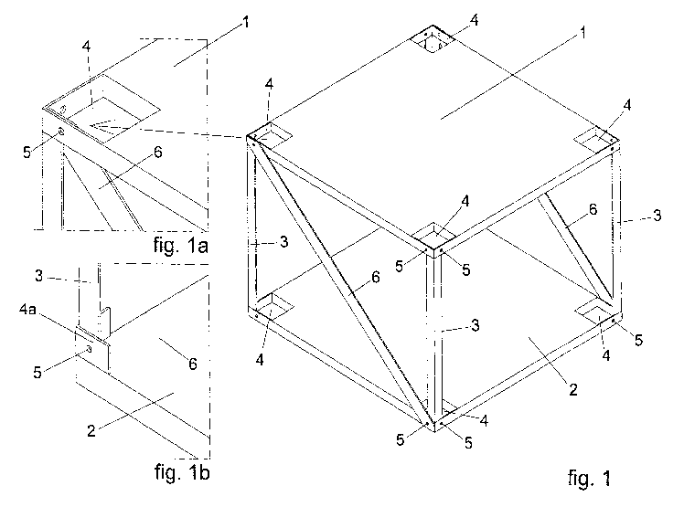
The invention relates to a double-shelled load-bearing structure module of any geometric shape, formed from a top secondary shell element (1) and a bottom secondary shell element (2), with which module, made of individual assembled load-bearing structure modules of this kind having statically necessary filling rods, a double-shelled load-bearing structure in the form of a primary shell structure is joined, wherein the secondary shell elements (1 and 2) have, in each corner, a connection pocket (4), which is open at the top or bottom or is open at the top and bottom, of appropriate size for connecting a plurality of load-bearing structure modules, which connection pocket, at least on the outside, that is on the outer vertical surfaces of the secondary shell elements (1 and 2) is delimited by preferably metal profiles or metal sheet. It is also possible to arrange connection tabs (4a) in each corner instead of connection pockets (4), which connection tabs are formed from angular surfaces, preferably metal sheet, protruding in the direction of the intermediate space between the secondary shell elements (1 and 2).


French Abstract

L'invention concerne un module de structure porteuse plane de forme géométrique quelconque, réalisé à double coque, constitué d'un élément de coque secondaire supérieur (1) et d'un élément de coque secondaire inférieur (2), avec lequel une structure porteuse plane à double coque sous la forme d'une structure porteuse à coque primaire est assemblée à partir de modules de structure porteuse plane individuels assemblés de ce type avec les barres de treillis nécessaires pour des raisons statiques. Les éléments de coque secondaires (1 et 2) possèdent dans chaque coin une poche de liaison (4) ouverte en haut ou en bas ou en haut et en bas de taille appropriée, servant à la liaison de plusieurs modules de structure porteuse plane, laquelle est délimitée au moins du côté extérieur, c'est-à-dire au niveau des surfaces verticales extérieures des éléments de coque secondaires (1 et 2) de préférence par des profilés métalliques ou des tôles métalliques. De même, il est possible de disposer dans chaque coins des pattes de liaison (4a) à la place des poches de liaison (4), lesquelles sont formées à partir de surfaces angulaires, de préférence des tôles métalliques, qui font respectivement saillie dans la direction de l'espace intermédiaire entre les éléments de coque secondaires (1 et 2).

Claims

Note: Claims are shown in the official language in which they were submitted.


Claims:
Claim 1:
Two shells executed tensile structure module that consists of a structure in
the form of a formed from six squares, octagonal, convex polyhedron with
twelve edges which forms a square in the special case of orthogonal
design, in which two opposing planes formed as surfaces having upper
and lower secondary shell elements (1 and 2), wherein the terms used to
describe the top and bottom, that the secondary shell elements (1 and 2)
are spaced apart and are being installed along the remaining four edges of
the cross bars (3) and replacement by statically necessary or expedient
diagonal bars (6) through connections at the corners of the upper and
lower secondary shell elements (1 and 2) with neighboring modules, a two-
shell surface structure is formed in the form of a primary shell supporting
framework with mono- or biaxial framework bearing action, in which the
edges of the secondary shell elements (1 and 2) of adjacent tensile
structure modules are together.
Claim 2:
Tensile structure module of claim 1, wherein the secondary shell elements
(1 and 2) in each corner of an open top or bottom or up and down,
Connecting pocket (4) of convenient size for connecting a plurality,
Tensile structure modules have another, which have at least at the outer
vertical surfaces of the secondary shell elements (1 and 2) stable and
mechanically strong limitations.
Claim 3:
Have tensile structure module of claim 1, wherein the secondary shell
elements (1 and 2) in each corner connecting lugs (4a), which are formed
from respectively in the direction of the intermediate space between the
secondary shell elements (1 and 2) projecting angular surfaces.
4

Claim 4:
Tensile structure module according to claim 1, wherein the filler of 90
degrees or approximately 90 degrees to the secondary shell elements (1
and 2) arranged transverse bars (3) and for receiving shell transverse
forces from diagonal bars (6) in static required number and arrangement
are formed.
Claim 5:
Flat structural module according to claim 1, wherein the space between the
Secondary shell elements (1 and 2) is to be used as an installation or
Verwahrraum.
Claim 6:
Tensile structure module of claim 5, wherein in use ä s in the space
between the secondary shell elements (1 and 2), subframes (10) are used,
which take over the function of the rods (3 and 6).
Claim 7:
Tensile structure module of claim 1, wherein the bivalve Tensile structure
result in the form of a primary shell support structure at any, meaningful
points on the module node (22) located at the corners of the secondary
shell elements (1 and 2), by means of line-shaped supports, for example
walls, (7) is supported or individual supports (8).
Claim 8:
Tensile structure module according to claim 1, wherein said additional
beams for supports which are to be arranged not directly to the module
node (22) (11), inclined struts (12) to the upper module corners or
reinforcements (13) of the lower
Secondary shell elements (2) are arranged, which derive the vertical load
on the nodes adjacent module (22).

Claim 9:
Tensile structure module according to claim 1, in which trapezoidal
secondary shell elements (1 and 2) are used in the construction of non-
linearly bound double-shell tensile structures in the form of primary shell
structures.
Claim 10:
Tensile structure module according to claim 1, wherein for the preparation
of
Primary shell structures are used with two-axis curvature of the truncated
pyramidal modules.
Claim 11:
Tensile structure module according to claim 1, wherein for the synthesis of
curvatures in bivalve shell structures in the form of primary shell structures
orthogonal modules fitted with spacer plates (14) and according to the
intended curvature adapter wedges (15) and wedge plates (16) are used.
Claim 12:
Tensile structure module according to claim 5, characterized in that not
constantly used furnishings during non-use in the space between the
secondary shell elements (1 and 2) to sink or to lift.
Claim 13:
Tensile structure module according to claim 5, characterized in that,
(1 and 2) rails are arranged in the space between the secondary shell
elements, storage containers are moved on or in those who are accessible
through one or more openings in one of the secondary shell elements (1
and 2).
6

Claim 14:
Tensile structure module according to claim 1, characterized, in that the,
Secondary shell elements (1 and 2) are at least partially equipped with
circumferential frame of angular profiles (19), on the lower horizontal leg
plates (20) with recesses in the corners to form the compound of pockets
(4) or have additionally arranged connecting flaps (4a) from suitable
materials are removably inserted, the side edges to ensure the diaphragm
action with pressure contact to the vertical angular shanks (19) are
inserted.
7

Description

Note: Descriptions are shown in the official language in which they were submitted.


CA 03050178 2019-07-15
Description:
Surface-supporting structure module
The invention relates to a two-shell surface-supporting structure module, in
which two-shell surface-supporting structures in the form of primary shell
supporting structures are formed, which in the further description are
referred to as primary shell supporting frameworks.
A prefabricated building system with a steel lattice structure consisting of
wall panels, ceiling panels and supporting supports is known from CN 102
174 858 A, which has special constructions of the components and
connection solutions between the components.
DE 3 415 344 Al describes a quick-release skeleton, in particular made of
steel, as a supporting structure for ceiling and wall panels of a building.
This solution is known as skeleton construction, which is used here with
special connection solutions,
Rod components (supports, bolts) are provided for the rapid mounting of
the skeleton.
Reversed reinforced concrete cassettes with crossed ribs in 3 planes are
known from EP 1 609 924 Al.
In this case, the lower plane 1 is formed from one. The invention relates to
a reinforced concrete slab, the plane 2 consisting of ribs and recesses and
the plane 3 consisting of plates/tiles resting on crossing points of the ribs
and having an upright for distributing conditioned air or plumbing lines. The
ceiling elements are supported at their corners on supports and are fixed by
special bolts. Devices are connected to one another.
GB 1,175,711 A describes crossed parallel truss girders for ceiling and roof
constructions, provided as a supporting structure.
Prefabricated grid sections made of crossed bending rods are known from
1

CA 03050178 2019-07-15
US 2009/0282766 Al, laid on parallel, flat, parallel truss girders made of
identical or similar profiles as the lattice sections. The truss girders lie
on
main supporting elements of the building (girder, walls) and the lattice
bosses are covered by removable plates. Undercovering formed by this
system is suspended on the flat truss girders or on main supporting
elements of the building, so that an approximately full-surface
CONFIRMATION COPY:
Accessibility to the intermediate space between the overlying grid ceiling
and suspended ceiling is achieved.
A disadvantage of all these known solutions is that no interaction of
spaced-apart surface elements with respect to the plate-carrying effect is
achieved and also relatively heavy solutions are involved.
The object of the invention is to propose a solution which overcomes the
disadvantages of the prior art and by the joining together of largely
identical, In order to economically produce primary shell supporting
frameworks which are to be prefabricated industrially in series, these
primary shell supporting frameworks, if required, can be assembled in a
partially pre-assembled, lightweight building can be installed in a wide
variety of different geometries in buildings of different constructions.
The solution according to the invention will be explained in more detail
below with reference to embodiments and figures.
The figures:
1 upper secondary shell elemenT
2 lower secondary shell element
3 crossbar

CA 03050178 2019-07-15
4 connecting bag
4a connecting strap
holes in 4 or 4a
6 diagonal bar
7 Supporting wall
8 single support
9 recess
subframes
11 traverse
12 diagonal strut
13 reinforcement of 2
14 spacer plate
adapter wedge
16 wedge disk
17 table
18 bed
19 angle profile
plate on 19
21 adapter elements
22 module nodes
3

Representative Drawing
A single figure which represents the drawing illustrating the invention.
Administrative Status

2024-08-01:As part of the Next Generation Patents (NGP) transition, the Canadian Patents Database (CPD) now contains a more detailed Event History, which replicates the Event Log of our new back-office solution.

Please note that "Inactive:" events refers to events no longer in use in our new back-office solution.

For a clearer understanding of the status of the application/patent presented on this page, the site Disclaimer , as well as the definitions for Patent , Event History , Maintenance Fee  and Payment History  should be consulted.

Event History

Description Date
Inactive: Dead - No reply to s.86(2) Rules requisition 2021-12-14
Application Not Reinstated by Deadline 2021-12-14
Deemed Abandoned - Failure to Respond to Maintenance Fee Notice 2021-08-19
Letter Sent 2021-02-19
Deemed Abandoned - Failure to Respond to an Examiner's Requisition 2020-12-14
Inactive: Report - No QC 2020-08-14
Examiner's Report 2020-08-14
Amendment Received - Voluntary Amendment 2020-05-20
Maintenance Request Received 2020-01-14
Common Representative Appointed 2019-10-30
Amendment Received - Voluntary Amendment 2019-08-22
Inactive: Cover page published 2019-08-12
Inactive: Acknowledgment of national entry - RFE 2019-07-31
Small Entity Declaration Determined Compliant 2019-07-25
Application Received - PCT 2019-07-25
Inactive: First IPC assigned 2019-07-25
Inactive: IPC assigned 2019-07-25
Letter Sent 2019-07-25
Request for Examination Requirements Determined Compliant 2019-07-15
All Requirements for Examination Determined Compliant 2019-07-15
National Entry Requirements Determined Compliant 2019-07-15
Application Published (Open to Public Inspection) 2018-08-23

Abandonment History

Abandonment Date Reason Reinstatement Date
2021-08-19
2020-12-14

Maintenance Fee

The last payment was received on 2020-01-14

Note : If the full payment has not been received on or before the date indicated, a further fee may be required which may be one of the following

  • the reinstatement fee;
  • the late payment fee; or
  • additional fee to reverse deemed expiry.

Patent fees are adjusted on the 1st of January every year. The amounts above are the current amounts if received by December 31 of the current year.
Please refer to the CIPO Patent Fees web page to see all current fee amounts.

Fee History

Fee Type Anniversary Year Due Date Paid Date
Request for examination - small 2019-07-15
Basic national fee - small 2019-07-15
MF (application, 2nd anniv.) - small 02 2020-02-19 2020-01-14
Owners on Record

Note: Records showing the ownership history in alphabetical order.

Current Owners on Record
BERND HEIDENREICH
Past Owners on Record
None
Past Owners that do not appear in the "Owners on Record" listing will appear in other documentation within the application.
Documents

To view selected files, please enter reCAPTCHA code :


To view images, click a link in the Document Description column. To download the documents, select one or more checkboxes in the first column and then click the "Download Selected in PDF format (Zip Archive)" or the "Download Selected as Single PDF" button.

List of published and non-published patent-specific documents on the CPD .

If you have any difficulty accessing content, you can call the Client Service Centre at 1-866-997-1936 or send them an e-mail at CIPO Client Service Centre.


Document
Description 
Date
(yyyy-mm-dd) 
Number of pages   Size of Image (KB) 
Drawings 2019-07-14 12 259
Abstract 2019-07-14 2 107
Claims 2019-07-14 4 124
Description 2019-07-14 3 90
Representative drawing 2019-07-14 1 27
Claims 2019-08-21 3 94
Description 2020-05-19 3 86
Acknowledgement of Request for Examination 2019-07-24 1 186
Notice of National Entry 2019-07-30 1 202
Reminder of maintenance fee due 2019-10-21 1 112
Courtesy - Abandonment Letter (R86(2)) 2021-02-07 1 549
Commissioner's Notice - Maintenance Fee for a Patent Application Not Paid 2021-04-05 1 528
Courtesy - Abandonment Letter (Maintenance Fee) 2021-09-08 1 552
International search report 2019-07-14 4 125
National entry request 2019-07-14 5 123
Patent cooperation treaty (PCT) 2019-07-14 1 60
Amendment - Claims 2019-07-14 3 111
Amendment / response to report 2019-08-21 4 127
Maintenance fee payment 2020-01-13 3 106
Amendment / response to report 2020-05-19 3 82
Examiner requisition 2020-08-13 6 339