Note: Descriptions are shown in the official language in which they were submitted.
CA 03050360 2019-07-16
WO 2018/166868
PCT/EP2018/055623
PROTECTION DEVICE FOR A SHELL-AND-TUBE EQUIPMENT
DESCRIPTION
Background of the invention
The present invention refers to a protection
device for a shell-and-tube equipment and, more
specifically, for tube-side inlet tube-sheets of a
shell-and-tube equipment, like heat exchangers and
reactors, where the tube-to-tube-sheet joint is of a
butt-weld type and is made from the tube-sheet bore
(also called "internal bore welding" or I.B.W.). The
protection device is aimed to protect the tube-sheet
bore from turbulence and erosion of fluid flowing on
tube-side.
Turbulent fluids at high velocity or of multiphase
type can engender damaging phenomena on shell-and-tube
equipment. Gases laden of solid particles or liquid
bubbles and liquids laden of solid particles or gas
bubbles are typical multiphase flows. When fluid
turbulence is locally high, the fluid heat transfer
coefficient is enhanced and therefore a local
overheating or overcooling may occur, leading to higher
thermal-mechanical stresses and corrosion in equipment
construction parts. When construction materials of the
equipment cannot bear impinging or shear action of a
high velocity or multiphase flow, erosion arises.
In shell-and-tube equipment, when the tube-side
inlet tube-sheet is connected to tubes by a butt-weld
joint made from the tube-sheet bore, the tube-sheet
bore may be subject to local high turbulence and
erosion. The fluid flowing on tube-side enters into the
tube-sheet bore and is in direct contact with the bore
surfaces since the tube, being connected to the tube-
-1-
CA 03050360 2019-07-16
WO 2018/166868
PCT/EP2018/055623
sheet from an internal bore welding, does not protect
the tube-sheet bore. As a consequence, if the inlet
tube-side fluid entering into the tube-sheet bore is,
for instance, at a higher temperature than the shell-
side fluid and is characterised by two-phases (gas-
solid, liquid-solid, gas-liquid), the fluid can locally
damage the tube-sheet bore, due to overheating or
erosion. Such a damage is dangerous since it can
significantly reduce the design life of the equipment.
A major example where shell-and-tube type heat
exchangers can suffer from erosion is represented by
the so called "quench" or "transfer-line" exchangers
(TLE), installed in steam cracking furnaces for
ethylene production. The process gas leaving the
furnace is at high temperature, high velocity and laden
of hydrocarbon particles. In the inlet section of the
TLE, the process gas can have a velocity in a range of
100 m/s to 150 m/s approximately. Accordingly, in such
an application, it is essential to adopt a design or a
device for protecting the tube-side inlet pressure
parts from local overheating and erosion, so to assure
operating reliability and long-life service.
Several devices for protecting tube-side inlet
tube-sheet and the tube-side inlet portion of tubes of
shell-and-tube equipment from erosion are known in the
state of the art. Conceptually, these known technical
solutions can be split into two major groups, i.e.:
- protection devices fully or partially inserted into
the tubes; and
- protection devices attached to the tubes, but not
inserted therein.
The protection devices of the first group can be
-2-
CA 03050360 2019-07-16
WO 2018/166868
PCT/EP2018/055623
either an erosion resistant protection device or a
sacrificial protection device. As a result, no erosion
can occur on the portion of tubes protected by the
protection device.
For example, document US 7252138 describes a heat
exchanger having a cladding on the tube-sheet and flow
through plugs welded thereon to prevent erosion,
extending inside the tubes. Document US
3707186
describes a heat exchanger having a refractory on one
side of the tube-sheet and funnel shaped ferrules
placed in the end of the tubes, extending inside the
tubes. Document US 4585057 describes a shell-and-tube
heat exchanger having funnel shaped tube extension
inlets made of erosion resistant material to protect
the tube-sheet, extending inside the tubes.
The above three patent documents are major
examples of protecting devices that are fully or
partially inserted into the tubes and therefore the
internal diameter of the protecting device is not
identical to the internal diameter of the tube. This
represents a discontinuity between the internal
diameter of the device and the internal diameter of the
tube, which can be source of local high turbulence and
erosion.
The protection devices of the second group are
usually manufactured as an extension of tubes and
therefore the erosion occurs on such extension. In
fact, the fluid at inlet of the device has a local high
turbulence, which is smoothed along the device before
reaching the tube. Such extensions can be replaced or
repaired.
For example, document FR 2508156 describes how the
-3-
CA 03050360 2019-07-16
WO 2018/166868
PCT/EP2018/055623
inlet ends of tubes of a shell-and-tube heat exchanger
are protected from erosion by providing them with
extension tubes, which can be welded to tubes or
expanded against tubes. Document DE 1109724 describes a
shell-and-tube heat exchanger having attached to tubes
replaceable tubular extensions to prevent erosion.
Document US 6779596 describes a tubular heat exchanger
having sacrificial extended tube lengths allowing for
periodic replacement the sacrificial sections that may
be cut-off and a new sacrificial section may be welded
on. Document US 4103738 describes a tubular heat
exchanger with replaceable inlet means in shape of
tubular extensions with the same diameter as the heat
exchanger tubes. The extensions may have bevelled ends.
Document US 4785877 describes a transfer-line heat
exchanger (i.e. a shell-and-tube heat exchanger for a
specific service) having hollow truncated cones which
are an extension of tubes.
The above five patent documents are major examples
of protecting devices that are connected to the tubes,
or are integral with tubes. These documents refer to a
shell-and-tube heat exchanger where the tubes are not
connected by an internal bore welding to the tube-
sheet. On the contrary, the tubes go inside the tube-
sheet bore either till to the tube-side face of the
tube-sheet or beyond the tube-side face of the tube-
sheet. Accordingly, the tube-sheet bore is protected by
the tube itself, and the protection device is not
claimed to protect the tube-sheet bore, but the first
portion of the tube.
Additionally, document EP 1331465 of the same
Applicant discloses a TLE exchanger of shell-and-tube
-4-
type wherein the tube-side inlet tube-sheet and the
exchanging tubes are welded together by a butt-weld
type welding, which eliminates discontinuities and
steps in the transition from tube-sheet to tubes.
Therefore, there are no obstacles along the gas path
that can cause impinging or erosion. On gas-side face,
the tube-sheet is protected by a lining (weld overlay)
of high-resistant erosion material, which is able to
withstand the impinging and shear action of hot gases
exiting from the steam cracking furnace. Such a
technical solution, which is shown in figure 2, has so
far been considered to be satisfactory in protecting
the gas-side face of the tube-sheet. In figure 2, the
inlet tube-sheets are shown at reference number 500,
the weld overlay at reference number 502, and the hot
gas is represented by the arrows 504.
However, erosion phenomena may also occur on the
internal walls of the tube-sheet bore and on the first
portion of the exchanging tubes. Such an erosion on the
internal walls of the tube-sheet bore and on the first
portion of the exchanging tubes is due to gas
turbulence, along with high metal operating
temperatures. Entrance of the tube-sheet bores
represents a strong discontinuity for the gas path and
therefore the tube-sheet bores are a source of
turbulence. Downstream of the entrance, the gas flow is
chaotic, not well developed from hydrodynamic
standpoint. As a consequence, shear and impinging
action of gas and hydrocarbon particles on bore and
tube walls occurs.
Summary of the invention
One object of the present invention is therefore
-5-
Date Recue/Date Received 2021-01-14
to provide a protection device for a shell-and-tube
equipment which is capable of resolving the
abovementioned drawbacks of the prior art in a simple,
-5A-
Date Recue/Date Received 2021-01-14
inexpensive and particularly functional manner.
In detail, one object of the present invention is
to provide a device for protecting the inlet tube-sheet
of a shell-and-tube equipment from erosion and high
turbulence due to fluid flowing on tube-side, wherein
tubes and tube-sheet are connected by a butt-weld joint
made from the tube-sheet bore, and wherein the
protection device consists of butts connected to tube-
side face of the tube-sheet. Each butt has an off-set
from the tube-side face of the tube-sheet and there is
no discontinuity between the internal diameter of the
butt and the tube-sheet bore diameter at said
connection. The protection device according to the
present invention is aimed to eliminate, or at least
mitigate, the risk of erosion and high local heat
transfer coefficient on the surface of the tube-sheet
bore, specifically when the inlet tube-side fluid is at
high velocity and temperature or with a multiphase
flow, like synthesis gases from reforming and
gasification processes, effluents from hydrocarbons
steam cracking furnaces and slurry type fluids.
This object is achieved according to the present
invention by providing a protection device for a shell-
and-tube equipment.
Specifically, this object is achieved by a shell-
and-tube equipment comprising a shell that surrounds a
tube bundle. The tube bundle comprises a plurality of
tubes. At least one end of each tube is joined to an
inlet tube-sheet provided with respective tube-sheet
bores for inlettinq a fluid in the shell-and-tube
equipment. The inlet tube-sheet is provided with a
first side, which receives the fluid, and with a second
-6-
Date Recue/Date Received 2021-01-14
side, which is opposite to said first side and on which
the tubes are joined. The inlet tube-sheet is connected
to each tube of the tube bundle, on said second side,
in such a way that each tube does not extend inside the
respective tube-sheet bore. The inlet tube-sheet is
provided, on at least part of said tube-sheet bores,
with respective tubular protection devices for
protecting said tube-sheet bores from high local
turbulence and erosion due to the fluid flowing into
said tube-sheet bores. Each tubular protection device
is made in the form of a butt, or a piece of tube, that
extends from said first side of the inlet tube-sheet at
a respective tube-sheet bore, wherein there is no
physical contact between the tubular protection devices
and the tubes of the shell-and-tube equipment.
Brief description of the drawings
The characteristics and advantages of a protection
device for a shell-and-tube equipment according to the
present invention will be clearer from the following
exemplifying and non-limiting description, with
reference to the enclosed schematic drawings, in which:
figure 1 is a schematic view of a shell-and-tube
equipment with horizontally arranged tube bundle;
figure 2 is a partial sectional view of a
protection device for a shell-and-tube equipment
according to the prior art;
figure 3 is a partial sectional view of a first
embodiment of a protection device for a shell-and-tube
equipment according to the present invention;
-7-
Date Recue/Date Received 2021-01-14
CA 03050360 2019-07-16
WO 2018/166868
PCT/EP2018/055623
figure 4 is a partial sectional view of a second
embodiment of a protection device for a shell-and-tube
equipment according to the present invention;
figure 5 is a partial sectional view of a third
embodiment of a protection device for a shell-and-tube
equipment according to the present invention; and
figure 6 is a partial sectional view of a fourth
embodiment as well as a fifth embodiment of a
protection device for a shell-and-tube equipment
according to the present invention.
Detailed description of the preferred embodiment
With reference to figure 1, a shell-and-tube
equipment 10, more specifically a shell-and-tube heat
exchanger 10, is shown. The shell-and-tube equipment 10
is of the type comprising a shell 12 that surrounds a
tube bundle 14. Although the shell-and-tube equipment
10 is shown in a horizontal orientation, it may also be
oriented vertically or at any angle with respect to a
horizontal surface.
The tube bundle 14 comprises a plurality of tubes
16. The tubes 16 can be of any shape, like U-shaped or
straight. At least one end of each tube 16 is joined to
an inlet tube-sheet 18 provided with respective tube-
sheet bores 20 for inletting a fluid 22 in the tubes 16
of the shell-and-tube equipment 10.
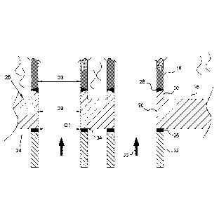
With reference now to figures 3 to 6, the inlet
tube-sheet 18 is provided with a first side 24, or
tube-side, which receives the inlet fluid 22, and with
a second side 26, or shell-side, which is opposite to
said tube-side 24. The fluid 22 is thus introduced into
the inlet tube-sheet 18 from the tube-side 24 and is
delivered into the tubes 16 laying on the shell-side
-8-
CA 03050360 2019-07-16
WO 2018/166868
PCT/EP2018/055623
26.
On the shell-side 26 the inlet tube-sheet 18 is
then connected to each tube 16 of the tube bundle 14,
preferably by means of a butt-weld joint 28 made from
inside a respective tube-sheet bore 20 of said inlet
tube-sheet 18 (this welding technique is also called
"internal bore welding" or I.B.W.). Therefore, the
butt-weld joint 28 stays on the shell-side 26 of the
inlet tube-sheet 18.
According to this butt-weld joint 28, the inlet
tube-sheet 18 is provided, on the shell-side 26, with
annular protrusions or necks 30 where respective tubes
16 are welded on. In other words, each tube 16 does not
extend inside the respective tube-sheet bore 20. As a
consequence, each tube-sheet bore 20 is not protected
by the respective tube 16 and the fluid flowing on the
tube-side 24 of the inlet tube-sheet 18 is in direct
contact with the tube-sheet bore 20.
According to the present invention, the inlet
tube-sheet 18 is provided, on at least part of its
tube-sheet bores 20, i.e. on at least some of the tube-
sheet bores 20, with respective tubular protection
devices 32 for protecting the tube-sheet bores 20 from
high local turbulence and erosion. In particular, the
inlet tube-sheet 18 is provided, on the rim of at least
part of its tube-sheet bores 20, with respective
tubular protection devices 32. More specifically, each
tubular protection device 32 is made in the form of a
butt, or a piece of tube, that extends from the first
side 24, or tube-side, of the inlet tube-sheet 18 at a
respective tube-sheet bore 20. In other words, each
tubular protection device 32 extends from the opposite
-9-
CA 03050360 2019-07-16
WO 2018/166868
PCT/EP2018/055623
side of the inlet tube-sheet 18 with respect to the
second side 26, or shell-side, of said inlet tube-sheet
18 where the tubes 16 are joined. Therefore, there is
no physical contact between the tubular protection
devices 32 and the tubes 16 of the shell-and-tube
equipment 10. The tubular protection device 32 does not
extend into the tube-sheet bore 20.
Additionally, each tubular protection device 32
has an internal diameter D1, measured at the joining
portion 34 between said tubular protection device 32
and the tube-side 24 of the inlet tube-sheet 18, that
is substantially identical to the internal diameter D2
of the respective tube-sheet bore 20. Preferably, the
internal diameter D1 of each tubular protection device
32 is also substantially identical to the internal
diameter D3 of the respective tube 16 placed at the
opposite side, i.e. the shell-side 26, of the inlet
tube-sheet 18.
According to the preferred but not limiting
embodiments shown in figures 3 to 5, each tubular
protection device 32 can be connected to the surface of
the tube-side 24 of the inlet tube-sheet 18, at the
respective joining portion 34, by three alternative
ways:
- each tubular protection device 32 is integral with
the tube-sheet 18, as shown in figure 3, that is, for
example, the tubular protection device 32 is made
from the tube-sheet 18 by machining;
- each tubular protection device 32 is welded to the
tube-sheet 18, as shown in figure 4, for example by
means of a weld seam 36;
- each tubular protection device 32 is welded to a
-10-
CA 03050360 2019-07-16
WO 2018/166868
PCT/EP2018/055623
lining 38 protecting the surface of the tube-side 24
of the inlet tube-sheet 18, as shown in figure 5, for
example by means of the interposition of a weld seam
36.
In all the connection configurations, each tubular
protection device 32 is thus characterized by the
following advantageous features:
- it is not in contact with the tubes 16; and
- at the joining portion 34 between the tubular
protection device 32 and the tube-side 24 of the
inlet tube-sheet 18, the internal diameter D1 of the
tubular protection device 32 is substantially
identical to the internal diameter D2 of the tube-
sheet bore 20, so that there is no discontinuity
between the bore of the tubular protection device 32
and the bore 20 of the inlet tube-sheet 18.
As previously mentioned, each tubular protection
device 32 has the first purpose to protect the
respective tube-sheet bore 20 from high local
turbulence and erosion due to the tube-side fluid 22
flowing into said tube-sheet bore 20. Depending on the
length of the tubular protection device 32, measured in
the tube-side fluid 22 flowing direction, and the
thickness of the inlet tube-sheet 18, the tubular
protection device 32 can also protect the first tube-
side portion of the tubes 16.
As known, a fluid at high velocity entering into a
bore from a larger domain increases its velocity and
changes its streamlines. This leads to an enhancement
of the local turbulence inside the bore. As a result:
- the local heat transfer coefficient increases and, if
the tube-side fluid 22 is hotter than the shell-side
-11-
CA 03050360 2019-07-16
WO 2018/166868
PCT/EP2018/055623
fluid, a local overheating on the tube-sheet bore 20
can occur; and
- in case of multiphase flow where a phase is abrasive,
the abrasive phase can shear or impinge the bore
surface, leading to erosion.
The protection of the tube-sheet bore 20 occurs
because of the respective tubular protection device 32
suitably regularizes the fluid-dynamics before the
tube-side fluid 22 reaches the tube-sheet bore 20. In
other words, if local high heat transfer coefficient or
erosion occur, they occur on the tubular protection
devices 32 and not on the tube-sheet bores 20.
As a result, the tube-sheet bore 20 is not
subject, for instance, to dangerous local overheating
when the tube-side fluid 22 is the hotter fluid and
therefore thermo-mechanical stresses and corrosion
phenomena on the inlet tube-sheet 18 are not primed or
enhanced. Moreover, the turbulence of the abrasive
phase, in case of multiphase flow, is regularized and
guided along the longitudinal direction of the tubes
axis.
Each tubular protection device 32 can be
manufactured either with the same construction material
of the inlet tube-sheet 18 (this occurs, for example,
in the embodiment of figure 3), or from a high erosion
resistant material. In all cases, the tubular
protection device 32 can be considered as a sacrificial
element that can be removed and replaced in case of
extended damages.
In order to improve the hydrodynamic smoothing
action of the tubular protection device 32, the free
end 40 of at least part of the tubular protection
-12-
CA 03050360 2019-07-16
WO 2018/166868
PCT/EP2018/055623
devices 32, i.e. the end 40 not connected to the
joining portion 34 of the inlet tube-sheet 18, can have
several shapes. Thus, the free end 40 of at least some
of the tubular protection devices 32 can have several
shapes. For example, as shown in figure 6, the free end
40 of each tubular protection device 32 can have a
bevelled shaped portion 42, wherein the internal
diameter D4 of said bevelled shaped portion 42,
measured at said free end 40, is greater than the
internal diameter D1 of the tubular protection device
32, measured at the joining portion 34 between said
tubular protection device 32 and the tube-side 24 of
the inlet tube-sheet 18. The internal diameter D4 of
the bevelled shaped portion 42, measured at the
respective free end 40, can also be substantially
identical to the external diameter D6 of the respective
tubular protection device 32.
Additionally, as once again shown in figure 6, the
free end 40 of at least part of the tubular protection
devices 32, i.e. the free end 40 of at least some of
the tubular protection devices 32, can also have a
funnel shaped portion 44, wherein the internal diameter
D5 of said funnel shaped portion 44, measured at said
free end 40, is greater than the internal diameter D4
of the above mentioned bevelled shaped portion 42. The
internal diameter D5 of the funnel shaped portion 44,
measured at the respective free end 40, can also be
greater than the external diameter D6 of the respective
tubular protection device 32. In any case, the final
smoothing action of the tubular protection device 32
can be set by changing the length of said tubular
protection device 32, measured in the tube-side fluid
-13-
CA 03050360 2019-07-16
WO 2018/166868
PCT/EP2018/055623
22 flowing direction, or the entry shape of the
respective free end 40.
At least part of the tubular protection devices
32, i.e. at least some of the tubular protection
devices 32, can be provided with a disc, such as a
circular or square disc, around the free end 40.
The tubular protection device 32 is applicable
whenever a shell-and-tube equipment 10 with a tube-to-
tube-sheet joint of butt-weld type made from the bore
has:
- an inlet tube-side fluid at high velocity which may
engender a local high heat transfer coefficient; and
- an inlet tube-side fluid with multiphase flow that
may engender erosion.
Some examples of fluids and relevant shell-and-
tube equipment 10 that may benefit from the use of the
tubular protection device 32 according to the present
invention are:
- transfer-line exchangers for effluents from steam
cracking furnaces for ethylene production;
- process gas boilers and coolers for synthesis gases
(reforming, gasification); and
- reactors for slurry fluids.
The shell-and-tube equipment may thus be a shell-
and-tube heat exchanger, in particular a shell-and-tube
transfer-line heat exchanger, a shell-and-tube process
gas boiler or cooler, or a shell-and-tube reactor, and
more particularly a shell-and tube transfer-line heat
exchanger or shell-and-tube process gas boiler or
cooler.
It is thus seen that the protection device for a
shell-and-tube equipment according to the present
-14-
CA 03050360 2019-07-16
WO 2018/166868
PCT/EP2018/055623
invention achieves the previously outlined objects.
The protection device for a shell-and-tube
equipment of the present invention thus conceived is
susceptible in any case of numerous modifications and
variants, all falling within the same inventive
concept; in addition, all the details can be
substituted by technically equivalent elements. In
practice, the materials used, as well as the shapes and
size, can be of any type according to the technical
requirements.
The protective scope of the invention is therefore
defined by the enclosed claims.
-15-