Note: Descriptions are shown in the official language in which they were submitted.
METHOD OF CONVERTING RAILCARS
Background
[0001] The invention relates generally to railcars, and more
particularly to
railcars for shipping automotive vehicles.
[0002] For many years, autorack railcars have been used for shipment of
automotive vehicles. Shipping by rail can significantly reduce costs as
compared
with shipping by tractor-trailer.
[0003] Prior art autorack railcars as shown in Figs. 1 and 3 typically
have side
walls that comprise a row of vertical posts extending along each side of the
railcar, with vertical columns of rectangular side screens supported between
adjacent posts. The side screens typically provide security for the vehicles
being
transported, while also having vent openings to avoid undesirably high
concentrations of automobile exhaust in the railcar interiors.
[0004] A roof extends across the width of the car between the side
walls.
Some prior art roof structures comprise a series of roof structure segments,
including end segments made of corrugated 14 gauge (.0785 in. thick)
galvanized
steel or non-corrugated 1/4 in. plate, and intermediate segments made of
corrugated
16 gauge (.0635 in. thick) galvanized steel, with each roof sheet having a
longitudinal dimension of about 4 ft., 3 in., i.e., about 51 in., with 22 roof
structure segments arranged in series on a railcar having a total length of
about 90
ft. The longitudinal dimension of some prior art segments is about 4 ft., 3
3/8 in.,
i.e., about 51 3/8 in., with overlaps providing an effective length of about 4
ft. for
each segment. As shown in Figs. 1 and 3, some prior art roofs include a
horizontal
top central portion, with inner sloped portions extending downward and outward
therefrom, and outer sloped portions extending downward and outward more
steeply from the inner sloped portions. Roof rails extend along the sides of
the
roof. The vertical dimension of some prior art roof structures including the
roof
rails is about 2 ft., 83/4 in.
[0005] One factor that limits the number of vehicles that can be
shipped on an
individual autorack railcar is that height limits are imposed on railcars due
to the
1
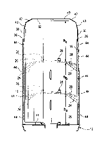
CA 3050402 2019-07-23
presence of bridges, tunnels and other obstructions over the railways.
Railroad
regulations specifying a maximum height at the center of the railcar, and
lower
maximum heights at certain distances from the center. The prior art includes
19'-
0" ATR auto racks meeting AAR Plate J specifications, and 20'2" auto racks
meeting AAR Plate K specifications.
[0006] Another factor that can limit the number of vehicles is the need
to
maintain the center of gravity (Cg) of the loaded railcar at or below a
certain
height above the top of the rail (ATR) for stability. The center of gravity is
affected by the weight of the vehicles being transported, and the height of
the
centers of gravity of the vehicles being transported, which can vary
significantly
between, e.g., relatively tall vehicles such as conventional gasoline-powered
SUV's as compared with, e.g., certain electric vehicles that have a relatively
low
profile, with weight concentrated in batteries near the bottom of the vehicle.
[0007] Bi-level autorack railcars are often used to ship automotive
vehicles
that have relatively high vertical dimensions, such as pick-up trucks, mini-
vans
and sport utility vehicles. Tr-level railcars are typically preferred for
shipping
lower height passenger cars. Tr-level cars can accommodate a larger number of
shorter vehicles than bi-level cars, thus increasing load factor and lowering
the
cost of transportation of such vehicles.
[0008] The demand for bi-level and tri-level autorack cars in North
America
at any time depends on the mix between shorter and taller vehicles being
transported in North America, which in turn depends on multiple ever-changing
factors, e.g., (I) customer demand in various regions, (2) percentages of
vehicle
types being built in various regions, and (3) percentages of vehicle types
arriving
at various ports. There is a need for railcars that can easily be modified
between
bi-level and tri-level configurations to accommodate changes in demand.
[0009] Many tri-level railcars have been constructed by building racks
on flat
cars. In some cases, the racks may be built on new flat cars that are custom
built
for autorack use. In other cases, the racks may be built on flat cars that
have been
built and used previously for other commercial rail service. In the latter
case, the
flat cars may exhibit configurational variation as a result of strain incurred
while
2
CA 3050402 2019-07-23
in service. This may impose challenges relating to construction of the racks,
but
nevertheless may be more desirable than using new flat cars, for economic
and/or
environmental reasons. In either case, the deck of the flat car typically
functions
as the first deck of the tri-level car, and the second and third decks are
supported
by the rack. The first, second, and third decks are commonly referred to as
the A,
B, and C decks respectively.
[0010] End doors to provide enhanced security in autorack cars are
described,
e.g., in U.S. Patents No. 3,995,563, No. 4,936,227, No. 5,829,360 and No.
5,765,486, the disclosures of which are incorporated herein by reference. End
doors typically include locking pins that engage the A deck, a fixed upper
deck,
and in some cases, the roof. In some cases, the locking pin enters the fixed
upper
deck from above, as shown in Fig. 1 of the '360 patent. The prior art also
includes
arrangements in which the locking pin enters a fixed upper deck of a bi-level
car
from below the deck.
[0011] One of the challenges in adapting flat cars for tri-level
autorack use is
that a low flat car deck height may be desirable for Cg purposes and overhead
clearance purposes, but a low deck height can create bottom clearance issues
relative to draft gear housing. The bottom clearance issues have typically
been
addressed through the use of ramps near the ends of the flat car, which raise
the
deck height near the ends of the flat car. Such ramps enable the flat car deck
to
have a central low portion along most of its length, providing a sufficiently
low
Cg for the loaded railcar, while providing adequate bottom clearance for most
automotive vehicles to clear the draft gear housing near the ends.
[0012] Tr-level cars typically have hinged end sections on their B
decks that
can be raised to provide clearance for automobiles being loaded on the A deck.
The hinged end sections are manually raised and lowered during loading and
unloading operations. The hinged end sections are placed in their lowered
positions to support automobiles.
[0013] In conventional tri-level cars heretofore used in commercial
rail
service, adequate clearance is generally not maintained if the same number of
vehicles is loaded on the A deck as on the B and C decks, requiring a reduced
3
CA 3050402 2019-07-23
number of vehicles to be transported on the A deck. While the B and C decks
can
generally accommodate five typical passenger cars each in a conventional tri-
level
railcar, the A deck can typically carry only four. Thus, the load factor for
conventional tri-level railcars is 14 for most passenger cars. Where four
vehicles
are carried on the A deck, the automobiles in the end positions typically are
inclined due to their location on the ramps.
[0014] With conventional tri-level cars, shippers must spend
significant
amounts of time determining the load makeup of a shipment. Load makeup refers
to the specific types of vehicles loaded at specific positions in a railcar.
Because
conventional tri-level cars have different clearances on different decks and
at
different positions within individual decks, only specific types of
automobiles can
be loaded at specific positions. Thus, loading a conventional tri-level car
entails
locating vehicles that can fit within each position and arranging all of the
vehicles
on the car to use the available capacity efficiently. In some cases, if no
automobiles are being shipped that fit within a particular position, the
position
remains empty, which can increase the number of railcars required to ship a
particular number of automobiles.
[0015] As consumers' preferences among different types of automobiles
fluctuate due to economic factors such as changes in fuel prices as well as
non-
economic factors, the mix of automobiles being shipped by rail changes and the
demand for various types of vehicle-carrying railcars fluctuates, as do the
load
makeup decisions. Increased demand for tri-level autorack railcars has been
met
in part by construction of new tri-level autorack railcars. Many older tri-
level cars
have a height of about 19 ft., 0 in ATR. Many cars constructed in recent years
have a height of about 20 ft., 2 in. ATR, taking advantage of increased
clearances
that have become available in certain areas in recent years. The increased
height
can enable taller automotive vehicles to be carried on the tri-level cars,
thereby
help to alleviate some of the constraints on load makeup with shorter autorack
railcars.
[0016] When demand for tri-level autorack railcars increases
simultaneously
with a decrease in demand for bi-level autorack railcars, conversion of bi-
level
4
CA 3050402 2019-07-23
autorack railcars to tri-level autorack railcars may be particularly
desirable. In the
past, autorack railcars having a height of about 19 ft., 0 in. ATR have been
converted to autorack railcars having a height of about 20 ft., 2 in. by
adding post
extensions and adding a row of side screens above the existing side screens.
U.S.
Patent No. 8,302,538, the disclosure of which is incorporated herein by
reference,
describes another method of converting a bi-level railcar to a tri-level
railcar that
comprises severing each of the posts between the flat car and the roof
structure,
thereby dividing the posts into upper and lower portions, possibly without
disconnecting the upper portions of the posts from the roof structure;
removing
upper portions of the posts with the roof structure; removing the upper deck
from
the portions of the posts to which it was affixed; adjusting the height of the
upper
deck and affixing the upper deck to portions of the posts; affixing a second
upper
deck to portions of the posts; adding extensions to portions of the posts; and
assembling the portions of the posts and the extensions. While prior art
conversion methods such as those described above may be useful, these methods
can be expensive, and can increase the height of the railcar's center of
gravity
significantly. There is a continuing need for improved methods that reduce the
time and cost of conversions, while also reducing increases in the height of
the
railcar's center of gravity.
Summary
[0017] There is
provided a method of increasing the height of a railcar
comprising removing the roof of the railcar, and replacing the roof with an
increased height roof structure comprising a horizontal top center portion,
sloping
intermediate portions extending downward and outward from the top center
portion, and side wall extension portions extending downward from the
intermediate portions, wherein the side wall extension portions eliminate the
need
to extend side wall post height or add side screens. In some embodiments, the
side
wall extension portions are vertical. In some embodiments, the side wall
extension portions are substantially vertical, within 100 of vertical, within
5 of
vertical, within 2 of vertical, or within 10 of vertical.
CA 3050402 2019-07-23
[0018] In some embodiments, the roof structure comprises a series of
roof
segments that are arranged along the length of the railcar with edges
overlapping
sufficiently to permit adjacent segments to be attached by fasteners such as
HuckBolts, by welding, and/or by other suitable means. In some embodiments,
each segment is an integral, one-piece, unitary structure that includes a
horizontal
top center portion, sloping intermediate portions, and vertical side wall
extension
portions.
[0019] In some embodiments, each segment of the roof structure may
consist
of a single sheet of material such as corrugated metal. In some embodiments,
the
corrugated metal may comprise galvanized steel, another steel material that
has a
protective coating to prevent or delay oxidation, aluminum, stainless steel,
or
other materials. The roof structure material preferably is light in weight to
facilitate provision of an acceptably low center of gravity while also being
strong
enough to be self-supporting and to provide protection for vehicles
transported
within the railcar. The roof structure may also contribute strength and
stiffness to
the railcar structure. In some embodiments, the roof structure may comprise a
series of roof structure segments, including end segments made of 14 gauge
(.0785 in. thick) galvanized steel, and intermediate segments made of 16 gauge
(.0635 in. thick) galvanized steel, with each roof sheet having a longitudinal
dimension of about 4 ft., with the roof sheets at the ends of the car being of
14
gauge galvanized steel, with 22 roof structure segments arranged in series on
a
railcar having a total length of about 90 ft. In some embodiments, each roof
sheet
may have a longitudinal dimension of between 51 in. and 52 in., or about 4
ft., 3
3/8 in. It is believed that the methods described herein can provide
advantages with
respect to efficiency and cost of conversion, as well as with respect to
maintaining
an acceptably low center of gravity for the autorack car during transport of
automotive vehicles.
[0020] In some embodiments, the methods may be used in converting
autorack railcars from bi-level to tri-level configuration in conjunction with
steps
such as augmenting internal deck configuration by adjusting the height of or
replacing the existing bi-level upper deck, and adding a second upper deck.
The
6
CA 3050402 2019-07-23
bi-level autorack car may have a height of, e.g., about 19 ft., 0 in. ATR, and
may
be converted into a tri-level autorack car having a height of about 20 ft., 2
in.,
with substantially vertical side wall extension portions having a vertical
dimension of at least 12 in.
[0021] In some embodiments, the new roof structure has a vertical
dimension
of about 3 ft., 10 1/4 in., and replaces a roof structure having a vertical
dimension
of about 2 ft., 8 % in. In other embodiments, the method may be used with
railcars
and roof structures of other dimensions. The method may also be used to
increase
the height of an autorack railcar without increasing the number of decks.
[0022] In some embodiments, the side wall extension portions cooperate
with
side screens to effectively increase side wall height without requiring
additional
side wall structure such as side screens or post extensions, with the side
wall
extension portions being lighter in average weight per unit area than the
combined
average weight per unit area of the side posts and side screens.
[0023] In some embodiments, ladders may be provided on each side near
both
ends of the railcars as is conventional, with spacing between the ladders and
the
side wall to permit a radial door to open with part of the door being between
the
ladder and the side wall. To facilitate worker access to a higher upper deck
after
conversion, convenience grabs or hand-holds may be provided on the side wall
extension portions of the roof to facilitate use of the ladders. . In some
embodiments, one or more convenience grabs or hand-holds may be provided
near the top of each end door above the elevation of the top rung of each
ladder,
so that when the door is open, the convenience grab or hand-hold is positioned
directly above the top rung of the ladder.
[0024] The method may include providing end door extensions to
increase
end door height, or replacing existing end doors with taller end doors. The
end
doors may be radial end doors such as Seal Safe end doors that have portions
extending over the top of the roof and that are pivotally supported on the
roof by
such portions, or may be other types of end doors.
[0025] In some embodiments, the method can be used to increase overall
height of a railcar in conjunction with conversion between a unilevel
7
CA 3050402 2019-07-23
configuration, a bi-level configuration and a tri-level configuration by
adding or
removing one or more decks.
[0026] In some embodiments, when the railcar is in a bi-level
configuration, a
third deck may be added by first removing the roof of the bi-level car, then
using
an overhead crane and/or other apparatus to lower the upper deck or B deck of
the
bi-level car, then using an overhead crane and/or other apparatus to lower an
additional deck into position as the C deck, and thereafter replacing the
roof.
[0027] In some embodiments, a bi-level autorack car may be built to the
maximum allowed height with an upper deck bolted in place. The upper deck
may have hinged end sections locked in the "level" position. That is, the B
deck
of the bi-level railcar may have pivotable end sections of the type normally
used
on the B deck of tri-level railcars, with the pivotable end sections being
secured in
place and not pivoted during normal operation of the bi-level railcar. The car
may
have a bolt-on roof structure. The car may be converted to a tri-level
configuration by removing the bolt-on roof structure, repositioning the
intermediate deck downward to the "tri-level" position with the end sections
able
to pivot up and down, installing from the top a second fixed end deck at its
"tri-
level" position, and reattaching the roof structure. The car could be
converted
back to a bi-level configuration by reversing these steps.
[0028] In some embodiments, a bi-level autorack car may be built with a
lower deck that has ends at a first elevation and a region of reduced
elevation
between the ends, similar to the lower deck configuration of conventional tri-
level
autorack cars, and with hinged end sections on the upper deck. The hinged end
sections may be similar to those used in conventional tri-level railcars, and
may
be raised and lowered during loading and unloading of the bi-level railcar. In
some embodiments, the hinged end sections are about 18 ft. long, and their
ends
are capable of being raised by about 9 in. to facilitate loading of the A deck
with
light trucks, e.g., pick-up trucks, as well as SUV's and vans. After loading
or
unloading, the hinged end sections may be lowered to generally horizontal
transport positions, creating a flat B deck.
8
CA 3050402 2019-07-23
[0029] Where hinged B deck end sections are provided, a B deck may
provide
less structural support for the autorack railcar than a B deck with fixed end
sections. To avoid excessive distortion of the autorack structure such as
racking or
"match boxing" in which the upper deck moves transversely relative to the
lower
deck in response to certain dynamic loads, braces or other structural
enhancements may be employed to compensate for reduced structural support
associated with hinged end sections.
[0030] In some embodiments, locking pins are provided to enable end
doors
to be locked in open positions during loading and unloading, and in closed
positions at other times. In these embodiments, each end door may have an
upper
locking pin and a lower locking pin. Each of the locking pins may be supported
for longitudinal vertical displacement in a bracket mounted on an inside
surface of
the door. To lock the door in closed position, the upper locking pin may
engage
an opening near the center of an upper deck, and the lower locking pin may
engage an opening in the A deck. To lock the door in open position, the upper
and
lower locking pins may engage respective openings near outer edges of the
upper
deck and A deck respectively. In some such embodiments, the upper locking pin
may be positioned to engage the upper deck from beneath the upper deck, with
the upper locking pin bracket positioned beneath the upper deck, and
optionally
with the opening(s) in the upper deck for receiving the locking pins when the
doors are closed being in hinged end sections of the upper deck.
[0031] In some embodiments, a conventional bi-level (which does not
have
hinged end sections on its B deck) may be converted to a tri-level of
increased
height having hinged end sections on its B deck by the following method:
removing the roof; removing the "B" deck; inserting a new "B" deck with hinged
ends; re-installing the "B" deck as a "C" deck; and installing a new increased
height roof structure with side wall extension portions as described above.
[0032] Other embodiments comprise building a mixed use bi-level railcar
with a roof structure having vertical side wall extension portions as
described
herein, in which the B deck is mounted much higher than in conventional bi-
level
railcars, e.g., at the height of the C deck in a tri-level railcar. A bi-level
car with
9
CA 3050402 2019-07-23
this configuration may be used to transport tall vans such as Ram ProMaster
vans,
Ford Transit vans, Mercedes Sprinter vans or other tall vehicles on its A deck
while transporting conventional vehicles on its B deck.
[0033] Another embodiment comprises building a mixed use bi-level
railcar
with a roof structure having vertical side wall extension portions as
described
herein, in which the B deck is mounted lower than in conventional bi-level
railcars, e.g., at the height of the B deck in a conventional tri-level car. A
bi-level
car with this configuration may be used to transport tall vans such as
Sprinter vans
or other tall vehicles on its B deck while transporting conventional vehicles
on its
A deck. This type of bi-level car can be built by removing the C deck from a
tri-
level railcar by any of the methods described in this application, and
providing an
increased height roof structure as described herein.
[0034] In some embodiments in which greater clearance is provide on one
deck than the other, the deck with greater clearance may have a clearance of,
e.g.,
over 99 in., over 100 in., or over 110 in., or over 111 in. More specifically,
in
some embodiments, the deck with greater clearance may have a clearance of,
e.g.,
99 in. to 111 in., 99 in. to 102 in., 109 to 111 in., about 110 in., or other
clearances suitable for the vehicles intended to be transported. In one
particular
configuration.
[0035] In any of the above embodiments, the railcar may have a height
of
about 20 ft., 2 in. AIR. In some embodiments, a series of connected bi-level
railcars may have varying B-deck heights, with a first railcar having a B-deck
height of 10 ft., 10 1/4 in. AIR, a second car adjacent thereto having a B
deck
height about 3 in. less, i.e., about 10 ft. 7 % in.; and with a third car
adjacent the
second one having a B deck height of 3 in. less than that of the second car,
i.e.,
about 10 ft. 4 3/4 in. A string of five auto rack railcars is often circus
loaded in a
single operation. Providing varying B deck heights in which adjacent railcars'
B
deck heights are within 3 in. of each other as described above would enable
railcars with varying deck heights and varying clearances to be loaded in a
single
cascade circus loading operation. Alternatively, or additionally, a small ramp
having a length of, e.g., 24 in. or less, may be provided at the ends of each
B
CA 3050402 2019-07-23
deck, with the ramp being capable of adjusting up 3 in. on each of the two
running
surfaces to facilitate circus loading among railcars with B decks at different
heights. Where B decks with hinged end sections are employed, the above
dimensions and descriptions are applicable to B decks in their transport
positions.
[0036] A method of installing a removable roof structure on an autorack
railcar having at least one deck for supporting automotive vehicles, side
walls
extending upward from the deck, and end doors which are movable between open
positions in which access to the railcar interior is permitted, and closed
positions
in which the interior of the railcar will be fully enclosed to prevent
unauthorized
access after installation of the roof, may comprise installing removable
longitudinal roof supports on upper portions of the side walls, and welding or
otherwise attaching the roof structure to the longitudinal roof supports.
Installing
removable longitudinal roof supports on upper portions of the side walls may
comprise bolting longitudinal members such as angle members or channel
members to upper ends of side wall posts.
[0037] The railcars built or converted by the methods described herein
may
comprise, for example, a tri-level railcar capable of transporting in
commercial
rail service increased percentages of passenger cars having certain
predetermined
characteristics with a load factor of at least 15, comprising: a pair of side
walls;
end doors at each end of the railcar; and first, second and third decks. The
railcar
may have substantially equal top and bottom clearances above each of said
decks
to enable automobiles having the predetermined characteristics to be loaded
onto,
transported to a destination on, and unloaded from all decks of the railcar
using
circus loading and unloading techniques, without the need to raise end
portions of
the second deck to provide increased vertical clearance for loading on the A
deck,
and without any clearance-related restrictions as to which individual
automobiles
are in which positions on the decks during transport of automobiles on the
railcar.
Each of the decks may provide sufficient clearance to permit any automobile
having the predetermined characteristics to be driven from a first end to a
second
end of the deck at a speed up to about 5 mph without any portion of the
passenger
car, other than the tires, contacting the deck. Each of the decks may be
11
CA 3050402 2019-07-23
substantially horizontal along substantially the entire length of each deck.
The
railcar may in some embodiments have an empty weight of no more than about
116,000 lbs. In some embodiments, the railcar, when fully loaded at up to
about
24,000 lbs. per deck with vehicles having the predetermined characteristics,
may
have a center of gravity or Cg no greater than 98 in. ATR. The railcar may
have a
removable roof structure and a fully enclosed interior. The removable roof
structure may be secured to the side walls by fasteners that are readily
accessible
from the interior but not from outside the railcar.
[0038] In some embodiments, the center of gravity of the railcar may be
maintained at an acceptably low elevation while substantially eliminating the
conventional height variations and ramps on the A deck. Elimination of the
above-described variations in A deck height in prior art tri-levels may not
only
alleviate ground clearance concerns associated with certain high performance
automobiles that have lower spoilers, but may also eliminate or reduce the
need to
provide extra clearance for vertical movement or bouncing associated with the
ramps near the ends of the A deck.
[0039] The railcar may comprise a unit car, i.e., a railcar having a
monocoque
body, or may comprise a rack built on a conventional flat car, a low-level
flat car,
an upsill flat car, or a flat car having a 39 '/2 ATR running surface. In one
approach where a flat car having a 39 'A ATR running surface is employed, the
railcar has an overall height of approximately 20%2". The B and C decks may be
permanently fixed, i.e. bolted or welded in place along their entire length,
rather
than having hinged end sections as in the prior art cars discussed above. In
some
embodiments, the A deck does not include ramps of the type described above
which automobiles must travel up or down during loading and unloading, or rest
on in an inclined orientation during transportation, but instead the A deck is
substantially horizontal with only minor variations in elevation.
[0040] In some embodiments, there is provided a tri-level autorack
railcar in
which the clearances above each of the three decks are approximately equal. A
minimum clearance of about 64 to 66 in., measured near the deck end 30" off
center may be provided for each of the decks. For the C deck, the minimum
12
CA 3050402 2019-07-23
clearance may need to be measured from the deck to roof-mounted door hardware
such as hardware associated with a roof-mounted radial door pivot, which may
be
as much as 1 to 2 in. below the roof.
Brief Description of Drawings
[0041] Fig. 1 is an end view of a prior art tri-level autorack railcar.
[0042] Fig. 2 is a sectional view of a tri-level autorack railcar made
from the
railcar of Fig. 1.
[0043] Fig. 3 is a sectional view of a prior art bi-level autorack
railcar.
[0044] Fig. 4 is a sectional view of an increased height bi-level
autorack
railcar made from the railcar of Fig. 3.
[0045] Fig. 5 is a sectional view of an increased height tri-level
autorack
railcar made from the railcar of Fig.3.
Detailed Description
[0046] The embodiments described herein comprise a method of shipping
automobiles, a railcar for shipping automobiles, and methods of manufacturing
and converting railcars for shipping automobiles.
[0047] Fig. 1 illustrates a prior art tri-level autorack railcar that
may be
converted into the increased height tri-level railcar of Fig. 2. The railcar
of Fig. 2
comprises a flat car 12 having a rack structure constructed thereon. The flat
car
has a deck 14 that functions as the A deck of the railcar. The A deck may be
at
substantially at the same elevation along its entire length. The rack
structure
comprises a plurality of vertical posts 16, and B and C decks 18 and 20
respectively supported by the posts. Side screens 44 are supported between
adjacent pairs of posts on each side of the railcar.
[0048] Each of the decks is connected directly to the posts to be
supported
thereby. Knee braces 24 add strength and stiffness. Tire guides 26 and a chock
track 28 are provided on each deck. Longitudinal members 36 such as roof rails
and/or top chords tie the vertical posts together at their upper ends.
13
CA 3050402 2019-07-23
[0049] A corrugated increased height roof structure 32 encloses the top
of the
car. The increased height roof structure comprises a horizontal top center
portion
40, inner intermediate portions 42 extending downward and outward on each side
of the top center portion, outer/lower intermediate portions 43 extending
downward and outward from the inner intermediate portions 42 on each side of
the roof structure, and vertical side wall extension portions 30 extending
downward from the outer/lower intermediate portions 43 on each side of the
roof
structure.
[0050] A pair of radial end doors enclose each end of the car. One end
door is
shown at 34 in Fig. 2. Minimum clearances of ha, hb and hc, measured 30" off
center, are maintained above the A, B and C decks respectively. The minimum
clearances may be equal or approximately equal, and may be, e.g., between 64
and 66 in.
[0051] The railcar may be based on a low-level flat car, a conventional
flat
car, an upsill flat car, or a flat car having a 39 1/2" ATR (above top of
rail) running
surface. To facilitate maintenance of appropriate clearances, high cambered
decks may be employed at both the B and C level. The overall height of the
railcar is preferably equal to the maximum height permissible in North America
under applicable AAR regulations, i.e., about 20' 2".
[0052] In some embodiments, when the railcar is in a bi-level
configuration, a
third deck may be added by first removing the roof of the bi-level car, then
lowering the upper deck or B deck of the bi-level car, then lowering an
additional
deck into position as the C deck using an overhead crane or other suitable
equipment, and thereafter replacing the original roof with an increased height
roof
structure as shown at 32 in Fig. 2.
[0053] In some embodiments, a bi-level autorack car may be built to the
maximum allowed height with an upper deck bolted in place. The upper deck of
the bi-level car may have hinged end sections locked in the "level" position.
That
is, the B deck of the bi-level railcar may have pivotable end sections of the
type
normally used on the B deck of tri-level railcars, with the pivotable end
sections
being secured in place and not pivoted during normal operation of the bi-level
14
CA 3050402 2019-07-23
railcar. The car may have a bolt-on roof. The car may be converted to a tri-
level
configuration by removing the bolt-on roof, repositioning the B deck downward
from the bi-level B deck position to the tri-level B deck position and
enabling the
end sections of the B deck to pivot up and down, adding a third deck by
lowering
it through the open top into the "tri-level" C deck position, fixing it in
place, e.g.,
by bolting or welding, and replacing the original roof with an increased
height
roof structure having vertical side wall extensions 30 as shown in Fig. 2.
[0054] Fig. 3 illustrates a prior art bi-level railcar that may be
converted to an
increased height autorack car such as that of Fig. 4 or Fig. 5 by replacing
its roof
with an increased height roof structure 116. The increased height roof
structure
comprises a horizontal top center portion 40, inner intermediate portions 42
extending downward and outward on each side of the top center portion,
outer/lower intermediate portions 43 extending downward and outward from the
inner intermediate portions 42 on each side of the roof structure, and
vertical side
wall extension portions 30 extending downward from the outer/lower
intermediate portions 43 on each side of the roof structure.
[0055] Fig. 4 illustrates an increased height bi-level autorack car 108
having a
first deck 110, a plurality of posts 114 extending upward on opposite sides
thereof, a second deck 112 supported on the posts 114 above the first deck,
and a
roof 116. Braces 118 extend upward and inward from the posts to the second
deck 112. The lower/outer ends of the braces are joined to plates 120 which
extend upward from the braces to the sides of the deck. The plates 120 are
preferably removably attached to posts 114 by bolts or other means to
facilitate
adjustment of deck position.
[0056] The bi-level car of Fig. 3 may be converted to the increased
height tri-
level car of Fig. 5 by removing the roof, disconnecting the upper deck 112
from
the posts, lowering it and securing it in the position shown in Fig. 5,
securing a
new "C" deck 122 above it, and replacing the original roof with an increased
height roof structure 116.
CA 3050402 2019-07-23
[0057] The new C deck 122 may have braces 118 and connecting plates
120,
attached thereto prior to installation. The braces and connecting plates may
be
bolted or otherwise fastened to the posts or other structure to secure the
deck 122.
[0058] The bi-level car of Fig. 20 may alternatively be converted to
the tri-
level car of Fig. 22 by other methods described herein. The tri-level car of
Fig. 22
may be converted to the bi-level car of Fig. 20 by reversing the steps of any
of the
methods described herein for converting bi-level cars to tri-level cars.
[0059] One additional method of converting railcars comprises
converting a
bi-level or tri-level auto-rack railcar to a unilevel railcar by removing the
roof
structure to facilitate crane access to the railcar interior; removing one or
more
decks from the railcar using a crane; and replacing the original roof with an
increased height roof structure as described herein to provide an interior
space
that is capable of accommodating and enclosing vehicles of a height greater
than
the spacing between the decks of the bi-level or tri-level car.
[0060] Another additional method comprises building a mixed use bi-
level
railcar in which the B deck is mounted much higher than in conventional bi-
level
railcars, e.g., at the height of the C deck in a tri-level railcar. A bi-level
car with
this configuration may be used to transport tall vans such as Sprinter vans or
other
tall vehicles on its A deck while transporting conventional vehicles on its B
deck.
This type of bi-level car can be built by removing the B deck from a tri-level
railcar by any of the methods described in this application without other
major
structural changes.
[0061] Another additional method comprises building a mixed use bi-
level
railcar in which the B deck is mounted lower than in conventional bi-level
railcars, e.g., at the height of the B deck in a conventional tri-level car. A
bi-level
car with this configuration may be used to transport tall vans such as
Sprinter vans
or other tall vehicles on its B deck while transporting conventional vehicles
on its
A deck. This type of bi-level car can be built by removing the C deck from a
tri-
level railcar by any of the methods described in this application without
other
major structural changes.
16
CA 3050402 2019-07-23
[0062] A method of installing a removable roof on an autorack railcar
may
comprise installing removable longitudinal roof supports 140 on upper portions
of
the side walls, and thereafter attaching the increased height roof structure
116 to
the removable longitudinal roof supports. Installing removable longitudinal
roof
supports on upper portions of the side walls may comprise bolting them to
upper
ends of side wall posts. The increased height roof structure 116 may comprise
a
plurality of sections, or may be one piece, end to end, with no transitions.
The
roof structure 116 may have offsets at its ends for radial end doors.
[0063] The roof supports 140 may comprise generally L-shaped angle
members extending the entire length of the railcar along each side. Each roof
support may comprise a horizontal bottom portion and a vertical portion. The
roof structure 116 may be welded to the vertical portion of the roof support
140
with an inner bead and/or an outer bead along the entire length of the roof or
along portions thereof. The roof supports 140 may be attached to the side wall
posts by fasteners. The fasteners are preferably easily removable from the
inside
of the railcar only. Each fastener may comprise, e.g., a bolt that engages a
nut
which may be welded to the roof support 140. In other embodiments, cap screws
may be employed with their heads on the outside of the car, and nuts secured
to
them on the inside of the railcar. In some embodiments, other fasteners may be
used. When replacing the roof, new fasteners may be used to secure it in
place,
with the fasteners, such as cap screws, bolts or the like, being loosely
secured
first, then torqued as required.
[0064] The invention is not limited to the embodiments described above.
The
invention is further described in the following claims.
17
CA 3050402 2019-07-23