Note: Descriptions are shown in the official language in which they were submitted.
METHOD FOR PRODUCING A ROTOR UNIT
The invention pertains to a method for producing a rotor
unit or a bearing unit, as well as to a respective rotor
unit or bearing unit, wherein the rotor unit is realized
with a rotor and a plain bearing bush for the rotatable
arrangement of the rotor on a spindle, wherein the plain
bearing bush is placed into a mould, and wherein the rotor
is produced by attaching a polymeric material to the plain
bearing bush in the mould by means of a transfer moulding
process or injection moulding process.
Rotor units of polymeric materials are sufficiently known
from the prior art and typically used as a component of a
canned motor or a pump, e.g. with an impeller formed on the
rotor unit, in heating circuits or in vehicles. In canned
motors, a rotor unit and a stator of the electric motor are
separated by a can, which is arranged in an air gap between
the stator and the rotor unit. This makes it possible to
hermetically separate the rotor unit from the stationary
components of the pump without the use of seals. In this
case, the rotor unit is driven in a brushless manner, i.e.
with a permanently magnetic or separately excited armature
of the rotor unit. The rotor and the plain bearing bush are
bathed in the medium to be conveyed in the pump, wherein a
pump wheel or an impeller is respectively arranged on one
end of the rotor. A tribological pairing of the spindle and
the plain bearing bush is subject to strict requirements in
order to ensure a long service life of the pump. Depending
on the medium to be conveyed, dirt particles in a bearing
gap of the spindle or roughening of a bearing surface of
the spindle due to corrosion can lead to increased wear of
the spindle or the plain bearing bush, respectively.
Since it should also be possible to cost-efficiently
produce the rotor unit in large quantities, however, the
plain bearing bush is produced of a suitable material by
- 1 -
CA 3050561 2019-07-25
means of sintering, transfer moulding or injection moulding
and mechanically processed or machined in order to comply
with the required tolerances of the bearing surfaces of the
plain bearing bush. The plain bearing bush is then placed
into a mould and a polymeric material, which typically
differs from the material of the plain bearing bush, is
injection-moulded around this plain bearing bush. For
example, an impeller and an armature of the thusly designed
rotor can be formed on the plain bearing bush in this
production step.
In known production methods, it is disadvantageous that the
transfer moulding process and the injection moulding
process are associated with broad tolerance ranges
depending on the materials used. In addition, this method
does not allow the production of a sufficiently cylindrical
bearing bore in the plain bearing bush, which is why a
slightly larger inside diameter of the bearing bore is
intentionally produced in a central region of the plain
bearing bush. However, an internal mandrel of the mould
used for this purpose then requires forced demoulding,
which negatively affects the functional characteristics
such as the inside diameter and dimensional and positional
tolerances. Another disadvantage can be seen in that the
required length tolerance requires postprocessing of the
one-piece plain bearing bush. Machining of at least a
length of the plain bearing bush and, if applicable, the
bore is required in order to comply with the desired
tolerances required for a long service life.
The present invention therefore is based on the objective
of proposing a method for producing a rotor unit, a rotor
unit for a canned motor and a pump with a rotor unit, which
respectively allow a cost-efficient production.
This objective is attained by means of a method with the
characteristics of claim 1 or 2, a rotor unit with the
- 2 -
CA 3050561 2019-07-25
characteristics of claim 22, a bearing unit with the
characteristics of claim 23 and a pump with the
characteristics of claim 24.
In the inventive method for producing a rotor unit, the
rotor unit is realized with a rotor and a plain bearing
bush for the rotatable arrangement of the rotor on a
spindle, wherein the plain bearing bush is placed into a
mould, wherein the rotor is produced by attaching a
polymeric material to the plain bearing bush in the mould
by means of a transfer moulding process or injection
moulding process, wherein the plain bearing bush is
composed of a first bush section and a second bush section
that is connected to the first bush section, wherein the
bush sections are placed into the mould, and wherein the
polymeric material is attached to the bush sections.
In the inventive method for producing a bearing unit, the
bearing unit is realized with a bearing housing and a plain
bearing bush for the rotatable arrangement of a spindle of
a rotor, wherein the plain bearing bush is placed into a
mould, wherein the bearing housing is produced by attaching
a polymeric material to the plain bearing bush in the mould
by means of a transfer moulding process or injection
moulding process, wherein the plain bearing bush is
composed of a first bush section and a second bush section
that is connected to the first bush section, wherein the
bush sections are placed into the mould, and wherein the
polymeric material is attached to the bush sections.
The plain bearing bush therefore is composed of at least
two parts, wherein the first bush section is directly or
indirectly connected to the second bush section. This is
simply realized by placing the respective bush sections
into the mould, e.g. on a mandrel. After the bush sections
have been placed into the mould, the polymeric material is
introduced into the mould by means of a transfer moulding
- 3 -
CA 3050561 2019-07-25
process or injection moulding process and respectively
fixed on the plain bearing bush or the bush sections by
curing. The injected polymeric material thereby
respectively forms the rotor of the rotor unit or the
bearing housing of the bearing unit. Since the plain
bearing bush is composed of at least two parts, it is
possible to produce the respective bush sections
independently of one another. In addition, an internal
mandrel no longer has to be realized in a crowned manner
and pulled out of the plain bearing bush. In fact, an
internal mandrel may now have a straight shoulder, which
ensures that the respective bush section only comes in
contact with the spindle at the desired locations.
Consequently, special postprocessing of bearing bores in
the respective bush sections is no longer required.
Furthermore, the first and the second bush section can then
be positioned relative to one another in the mould such
that a desired length of the plain bearing bush is
adjusted. Machining of the thusly produced plain bearing
bush can thereby also be eliminated such that the
production costs of a rotor unit or bearing unit can be
significantly reduced.
The first bush section may form a first radial bearing
surface on a first axial end of the plain bearing bush and
the second bush section may form a second radial bearing
surface on a second axial end lying opposite of the first
end. Accordingly, the plain bearing bush may on its ends
form a respective bearing surface, which can come in
contact with a spindle, within a bearing bore in the plain
bearing bush. In this case, the bearing bore can have a
comparatively larger inside diameter between the respective
bearing surfaces such that a gap is formed between the
spindle and the plain bearing bush or the respective bush
section. Consequently, only the respective ends of the
plain bearing bush have to be produced such that they lie
within a dimensional tolerance. In this respect, it is also
- 4 -
CA 3050561 2019-07-25
particularly advantageous that the radial bearing surfaces
are in principle realized independently of one another
because the respective bearing surface can adapt its
position relative to the spindle. The adaptation may take
place when the bush section is placed into the mould, e.g.
on a mandrel that has the shape of the spindle. In this
case, it is furthermore possible to realize the bush
sections and therefore also the shaft used with different
inside diameters, for example, in order to adapt the bush
sections to bearing forces, a sliding speed or a structural
space. An angular arrangement of the bearing surface
transverse to the spindle, which occurs in one-piece plain
bearing bushes according to the prior art, is thereby
prevented. All in all, the service life of the plain
bearing bush and therefore of the respective rotor unit or
bearing unit can thereby also be prolonged.
Furthermore, the first bush section and/or the second bush
section may be formed with an axial bearing surface by the
respective axial ends. In this case, it is also possible to
precisely position the respective rotor unit or bearing
unit on a spindle in the axial direction. For example, an
axial contact surface for contacting the axial bearing
surface may be formed on the spindle. The plain bearing
bush may comprise a connecting section, by means of which
the first bush section and the second bush section are
connected to one another. The connecting section may be
realized in the form of an additional component of the
rotor unit. For example, the connecting section may be a
sleeve that is fixed on the first bush section and the
second bush section. In this case, the insertion of the
connecting section also makes it possible to prevent the
polymeric material of the rotor or the bearing housing from
reaching bearing surfaces of the bush sections during its
injection into the mould. The connecting section preferably
forms a gap between the spindle and the plain bearing bush.
Furthermore, a length of the plain bearing bush can be
- 5 -
CA 3050561 2019-07-25
varied as needed by means of the connecting section such
that the bush sections can in principle be realized
identically and the production therefore can be
additionally simplified.
Alternatively, the first bush section and/or the second
bush section may form a connecting section, by means of
which the first bush section and the second bush section
are connected to one another. Accordingly, the connecting
section may be formed by one of the bush sections, as well
as by both bush sections. In this case, the connecting
section is formed on a bush section or both bush sections
such that that a clearance between the bush sections is
bridged by the connecting section. This likewise makes it
possible to prevent polymeric material from reaching
bearing surfaces of the bush sections during its injection
into the mould. The integral design of the connecting
section with the bush section or the bush sections makes it
possible to realize the plain bearing bush without an
additional component. Furthermore, the connecting section
may also be realized in such a way that a length of the
plain bearing bush can be varied within defined limits.
The connecting section may be realized with such an inside
diameter that a gap is formed with respect to the spindle.
The connecting section particularly may be realized in a
sleeve-shaped manner and have such an inside diameter that
a radial gap is formed between the connecting section and
the spindle. In this case, the plain bearing bush
particularly can be realized with respective radial bearing
surfaces on opposite ends of the plain bearing bush.
Consequently, only the bearing surfaces have to be realized
centrically relative to the spindle rather than the entire
bearing bore of the plain bearing bush.
The plain bearing bush may be encased, preferably
completely enclosed radially, by the polymeric material. In
- 6 -
CA 3050561 2019-07-25
this way, the plain bearing bush can be integrally and/or
positively connected to the rotor or the bearing housing,
respectively. A relative position of the respective bush
sections can be fixed during the transfer moulding process
or the injection moulding process by curing the polymeric
material.
A connecting fit, which allows a relative motion between
the bush sections in the axial direction, may be produced
between the first bush section and the second bush section.
The connecting fit may be produced between a bore and a
shaft, wherein the bore is formed on one bush section and
the shaft is formed on the other bush section. The
connecting fit then allows a relative motion between the
bush sections in the axial direction such that the bush
sections can during the placement into the mould, e.g. on a
mandrel, be positioned in such a way that a desired length
of the plain bearing bush is achieved.
The connecting fit may be designed with an inside diameter
and an outside diameter on the bush sections, wherein the
connecting fit may in this case be realized tight with
respect to the polymeric material. The connecting fit
accordingly forms a seal that prevents the polymeric
material from passing through the connecting fit during its
injection into the mould. In this way, no polymeric
material can reach the respective bearing surfaces of the
bush sections.
The first bush section and the second bush section may be
designed and arranged in the mould in such a way that a
radial gap is at least sectionally formed between the first
bush section and the second bush section, wherein the
polymeric material can penetrate into the radial gap during
the transfer moulding or injection moulding process. The
radial gap ensures more precise positioning of the bush
sections relative to one another, wherein the bush sections
- 7 -
CA 3050561 2019-07-25
of the finished rotor unit or bearing unit are prevented
from being pushed together because cured polymeric material
is located in the radial gap.
Nevertheless, a relative motion between the bush sections
in the axial direction against respective inner surfaces of
the mould can be realized by means of an injection pressure
during the transfer moulding or injection moulding process.
This effect particularly can be achieved in that a radial
gap, into which the polymeric material can penetrate, is
formed between the bush sections. The injection pressure
can act upon respective axial faces of the bush sections,
which lie opposite of one another and form the radial gap,
and press apart these bush sections in the axial direction
in such a way that the gap is increased and the bush
sections are pressed against the respective inner surfaces
of the mould. In this way, the length of the plain bearing
bush can be realized even truer to size without requiring
any machining of the plain bearing bush.
It is furthermore possible to design the mould with
receptacles for a first axial end of the first bush section
and a second axial end of the second bush section, wherein
the bush sections can be inserted into the respective
receptacles, and wherein the receptacles can seal the axial
ends with respect to the polymeric material during the
transfer moulding or injection moulding process. For
example, the respective receptacle may be realized in the
form of a blind bore, into which the respective bush
section is inserted. It is important to design the
receptacles in such a way that the polymeric material is
unable to respectively reach axial ends of the bush
sections or axial bearing surfaces of the bush sections
during its injection into the mould.
The rotor or the bearing housing may be respectively made
of a fiber-reinforced polymeric material. The fibers used
- 8 -
CA 3050561 2019-07-25
may consist of carbon fibers or glass fibers, preferably in
the form of short fibers. Short fibers may have a length
between a few millimeters and 2 cm. Long fibers may
alternatively also be used, for example when using
partially preformed moulding materials.
A thermosetting polymer, preferably phenolic resin, epoxy
resin, polyester resin or polycyclopentadiene resin, or a
thermoplastic polymer, preferably
polypropylene,
polyphenylene sulfide or polyetheretherketone, may be used
as polymeric material.
The bush sections may be made of carbon, preferably of
graphite, graphite with phenolic resin impregnation, a
carbonized, graphite-filled phenolic resin compound, fiber-
reinforced polymer or ceramic. Furthermore, gap dimensions
between the spindle and a plain bearing formed by the plain
bearing bush can be adapted to thermal coefficients of
expansion and a water absorption or swelling behavior of
the materials under operating conditions. For example,
hydrophobic additives or postprocessing of the friction
partners, e.g. by means of silicones, may be used for
reducing a water absorption and a swelling behavior.
Consequently, an additional filler in the form of graphite,
molybdenum sulfide, tungsten
disulfide,
polytetrafluoroethylene, glass spheres and/or mineral
additives may be added to the polymeric material of the
bush sections. The addition of another filler particularly
makes it possible to achieve a further improvement of a
friction value. In this case, a starting resistance of the
rotor unit may be comparatively low after a prolonged
standstill of a pump. However, the bush sections may also
be made of different materials. In this way, the bush
sections can be optimally adapted to a respective stress of
a bearing surface of a bush section. For example, a bush
section located in the region of an impeller of the rotor
- 9 -
CA 3050561 2019-07-25
unit may have different material properties or tribological
properties than a bush section located in the region of an
armature of the rotor unit. The choice of different
materials for the respective bush sections makes it
possible to optimize a friction behavior of the plain
bearing bush such that a prolonged service life of the
respective rotor unit or bearing unit is achieved.
The first bush section may be produced by means of
machining and the second bush section may be produced by
means of a transfer moulding or injection moulding process
or vise versa. One of the bush sections may be machined on
bearing surfaces after its production in order to achieve
particularly sound sliding properties and a desired
clearance fit between the spindle and the bush section. In
this context, machining refers to material removal of any
type, e.g. by means of turning, grinding or polishing. This
type of machining makes it possible to significantly reduce
a roughness of the plain bearing bush or the bush section
on the bearing surfaces such that improved sliding
properties can be achieved.
The plain bearing bush may be designed with a length-
diameter ratio of 5:1 or greater. Accordingly, a length of
the plain bearing bush may be significantly greater than an
inside diameter of the plain bearing bush.
A permanent magnet or a cage winding of the rotor unit or
the bearing unit may be placed into the mould and joined
with the rotor or the bearing housing in the mould by means
of the transfer moulding process or the injection moulding
process. In this case, a permanent magnet or a cage winding
no longer has to be pressed on or bonded to the plain
bearing bush or the rotor. In this way, the permanent
magnet or the cage winding can be integrally and/or
positively connected to the rotor or the bearing housing in
an inseparable manner.
- 10 -
CA 3050561 2019-07-25
The permanent magnet or the cage winding also may be
encased, preferably completely enclosed, by the polymeric
material. According to the prior art, permanent magnets or
cage windings on the respective rotor are additionally
encapsulated in order to protect these permanent magnets or
cage windings from a medium to be conveyed. This additional
process step also can be eliminated because the permanent
magnet or the cage winding can already be encased or
enclosed by the polymeric material during the production of
the rotor within the mould such that the permanent magnet
or the cage winding may be completely embedded in the
material of the rotor. The receptacle, into which the
permanent magnet or the cage winding is simply inserted,
may alternatively also be formed on the rotor or the
bearing housing, wherein the receptacle may form an
enclosure in this case. The rotor or the bearing housing
also may be joined with the permanent magnet in the mould,
wherein the permanent magnet may be made of a thermoplastic
or thermosetting magnetic compound. In addition, the
permanent magnet can also be magnetized in a mould. It is
furthermore possible to simultaneously produce the
respective rotor or bearing housing and the permanent
magnet in the mould by means of a two-component injection
moulding process.
The inventive rotor unit for a canned motor is realized
with a rotor and a plain bearing bush for the rotatable
arrangement of the rotor on a spindle, wherein the rotor is
produced by attaching a polymeric material to the plain
bearing bush in a mould by means of a transfer moulding
process or injection moulding process, wherein the plain
bearing bush is composed of a first bush section and a
second bush section that is connected to the first bush
section, and wherein the polymeric material is attached to
the bush sections. With respect to the advantages of the
- 11 -
CA 3050561 2019-07-25
inventive rotor unit, we refer to the description of the
advantages of the inventive method.
Other advantageous embodiments of a rotor unit result from
the characteristics of the dependent claims, which refer to
claim 1.
The inventive bearing unit for a canned motor is realized
with a bearing housing and a plain bearing bush for the
rotatable arrangement of a spindle of a rotor, wherein the
bearing housing is produced by attaching a polymeric
material to the plain bearing bush in a mould by means of a
transfer moulding process or injection moulding process,
wherein the plain bearing bush is composed of a first bush
section and a second bush section that is connected to the
first bush section, and wherein the polymeric material is
attached to the bush sections.
Other advantageous embodiments of a bearing unit result
from the characteristics of the dependent claims, which
refer to claim 2.
The inventive pump comprises an inventive rotor unit or
bearing unit. In this respect, advantageous embodiments of
a pump also result from the characteristics of the
dependent claims, which respectively refer to claim 1 or
claim 2.
An embodiment of the invention is described in greater
detail below with reference to the attached drawings.
In these drawings:
Figure 1 shows a longitudinal section through a rotor unit
according to the prior art; and
- 12 -
CA 3050561 2019-07-25
Figure 2 shows a longitudinal section through a plain
bearing bush in a mould.
Figure 1 shows a rotor unit 10 according to the prior art,
wherein the rotor unit 10 is composed of a rotor 11 and a
plain bearing bush 12. The rotor 11 consists of a polymeric
material, which was attached to the plain bearing bush 12
in a not-shown mould by means of a transfer moulding
process or injection moulding process. The rotor 11 forms
an impeller 13 and comprises an armature 14, which forms
part of a not-shown canned motor for driving the impeller
13. The rotor unit 10 can be placed on a not-shown spindle
in order to thereby rotate about the rotational axis 15 of
the rotor unit 10. In the process, radial bearing surfaces
16 of the plain bearing bush 12 come in contact with the
spindle, wherein an inside diameter 17 of a bearing bore 18
of the plain bearing bush 12 lying between the radial
bearing surfaces 16 is larger than an inside diameter 19 of
the radial bearing surfaces 16. A gap, which is not visible
in this figure, can thereby be formed between the not-shown
spindle and the inside diameter 17. The plain bearing bush
12 is produced in one piece by means of a transfer moulding
process or injection moulding process, wherein the material
of the plain bearing bush 12 differs from the polymeric
material of the rotor 11.
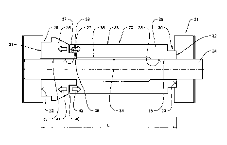
Figure 2 shows a longitudinal section through a plain
bearing bush 20 in a mould 21. The plain bearing bush 20
can be encased with a polymeric material in the mould 21,
for example in order to produce the rotor shown in Figure
1. The schematically indicated mould 21 has opposite inner
surfaces 22 and 23 and comprises a mandrel 24, on which the
plain bearing bush 20 is placed. The plain bearing bush 20
is composed of a first bush section 25 and a second bush
section 26, wherein the first bush section 25 is connected
to the second bush section 26. In this case, the first bush
section 25 forms a first radial bearing surface 27 and the
- 13 -
CA 3050561 2019-07-25
second bush section 26 forms a second radial bearing
surface 28. A first axial bearing surface 31 is formed on a
first axial end 29 of the first bush section 25 and a
second axial bearing surface 32 is formed on a second axial
end 30 of the second bush section 26. The first axial
bearing surface 31 and the second axial bearing surface 32
tightly abut on the respective inner surfaces 22 and 23 of
the mould. In this case, a distance between the inner
surfaces 22 and 23 of the mould essentially corresponds to
a length L of the plain bearing bush 20.
The second bush section 26 forms a connecting section 33
with an inside diameter 34, which is larger than an inside
diameter 35 of the radial bearing surfaces 27 and 28 such
that a gap 36 is formed on the mandrel 34 in the connecting
section 33. In addition, a connecting fit 37 is produced
between the first bush section 25 and the second bush
section 26 with an inside diameter 38 on the second bush
section 26 and an outside diameter 39 on the first bush
section 25. The connecting fit 37 allows a relative motion
between the bush sections 25 and 26, wherein the connecting
fit 37 prevents polymeric material from passing into the
gap 36 during its injection into the mould 21.
A radial gap 40, into which the polymeric material
penetrates during the transfer moulding or injection
moulding process, furthermore is formed between the first
bush section 25 and the second bush section 26 in the
region of the connecting fit 37. As a result, the first
bush section 25 and the second bush section 26 are
respectively pressed in the direction of the arrows 41 and
42 such that the first axial bearing surface 31 and the
second axial bearing surface 32 are pressed against the
respective inner surfaces 22 and 23 of the mould. In this
case, mechanical processing of the plain bearing bush 20 is
no longer required after the polymeric material of the
rotor has cured. A potential shrinkage can be ignored
- 14 -
CA 3050561 2019-07-25
during the production of the bush sections 25 and 26
because the already finished bush sections 25 and 26 are
adapted to the length L of the plain bearing bush 20 in the
mould 21. Nevertheless, it is possible to choose different
materials for the bush sections 25 and 26 in order to adapt
the bush sections 25 and 26 even better to a potential
load. In the plain bearing bush 20, the first bush section
25 is arranged in the region of a not-shown impeller of the
rotor.
- 15 -
CA 3050561 2019-07-25