Note: Descriptions are shown in the official language in which they were submitted.
CA 03050613 2019-07-17
1
SHEET-FED PRINTING PRESS FOR SIMULTANEOUS RECTO-VERSO PRINTING OF
SHEETS, IN PARTICULAR FOR THE PRODUCTION OF SECURITY DOCUMENTS
TECHNICAL FIELD
The present invention generally relates to a sheet-fed printing press adapted
to carry out
recto-verso printing of individual sheets, in particular for the production of
security
documents such as banknotes, comprising one or more printing units each
adapted to
carry out simultaneous recto-verso printing of the sheets, each printing unit
including two
printing cylinders cooperating with one another and forming a printing nip
where both
sides of the sheets are simultaneously printed, the two printing cylinders
each collecting
ink patterns from at least two associated plate cylinders. The invention
especially relates
to a printing press preferably comprising a printing unit with at least a
printing group
designed to print a first side and/or a second side of the substrate by
collecting different
impressions or ink patterns in their respective colours on a cylinder, e. g. a
collecting
cylinder, in advance before being printed onto the substrate.
BACKGROUND OF THE INVENTION
Such printing presses are known as such in the art, in particular from
European Patent
Publication No. EP 0 949 069 Al and International PCT Publications Nos. WO
2007/042919 A2, WO 2007/105059 Al, WO 2007/105061 Al, WO 2008/099330 A2, WO
2014/056711 Al, WO 2016/042482A2 and WO 2016/071870 Al.
International PCT Publication No. WO
2007/042919 A2 in particular discloses a recto-verso offset printing press
adapted to carry
out simultaneous recto-verso printing of sheets that further comprises an
additional
printing group placed upstream of a main printing group of the printing press.
CA 03050613 2019-07-17
WO 2018/167064 PCT/EP2018/056247
2
Figures 1 and 2 illustrate such a recto-verso printing press that is adapted
to carry out
simultaneous recto-verso printing of sheets S, as typically used for the
production of
banknotes and like security documents, which printing press is designated
globally by
reference numeral 100. Such printing press is in particular marketed by the
present
Applicant under the product designation Super Simultane IV. The basic
configuration of
the printing press 100 shown in Figures 1 and 2 is similar to that shown and
discussed
with reference to Figure 1 of International PCT Publication No. WO 2007/042919
A2. This
type of printing press is typically designated as a so-called "Simultan" (or
"Simultan-
offset") press owing to the fact that multiple colours are collected on a
common blanket
before being simultaneously transferred to the sheets S.
This printing press 100 comprises a printing unit 2, which is specifically
adapted to
perform simultaneous recto-verso printing of the sheets S (according to the so-
called
Simultan-offset printing principle) and comprises, as is typical in the art,
two blanket
cylinders (or printing cylinders) 5, 6 rotating in the directions indicated by
the arrows and
between which the sheets S are fed to receive multicolour impressions on both
sides,
namely on the recto and verso sides. In this example, blanket cylinders 5, 6
are three-
segment cylinders which are supported between a pair of side frames designated
by
reference numeral 20. The blanket cylinders 5, 6 receive and collect different
ink patterns
in their respective colours from plate cylinders 15 and 16 (four on each side)
which are
distributed around a portion of the circumference of the blanket cylinders 5,
6. These plate
cylinders 15 and 16, which each carry a corresponding printing plate, are
themselves
inked by corresponding inking apparatuses 25 and 26, respectively. The two
groups of
inking apparatuses 25, 26 are advantageously supported in two inking carriages
21, 22
that can be moved toward or away from the centrally-located plate cylinders
15, 16 and
blanket cylinders 5, 6.
As is known in the art, each printing plate is wrapped around the
corresponding plate
CA 03050613 2019-07-17
3
cylinder 15, 16 and clamped at its leading end and trailing end by a suitable
plate
clamping system, which plate clamping system is located in a corresponding
cylinder pit of
the plate cylinder (see e.g. International (POT) Publications Nos. 'NO
2013/001518 Al,
WO 2013/001009 Al and WO 2013/001010 A2).
Sheets S are fed from a sheet feeder 1 onto a feeder table 1* located next to
the printing
unit 2 (on the right-hand side in Figures 1 and 2) to a succession of transfer
cylinders 9,
8', 10 (three cylinders in this example) placed upstream of the blanket
cylinders 5, 6.
While being transported by the transfer cylinder 8', the sheets S receive a
first impression
on a first side of the sheets S (namely the upper ¨ or recto ¨ side in the
illustrated
example, which side is identified by a black triangle in the drawings by
opposition to the
lower ¨ or verso ¨ side, which is identified by a white triangle) using an
additional printing
group, the transfer cylinder 8' fulfilling the additional function of
impression cylinder. This
additional printing group consists of, in addition to the transfer cylinder
8', a blanket
cylinder 8 (a two-segment cylinder in this example) that collects inks from
two plate
cylinders 18 that are inked by corresponding inking apparatuses 28. The inking
apparatuses 28 are advantageously supported in an inking carriage 24 that can
be moved
toward or away from the plate cylinders 18 and blanket cylinder 8. The sheets
S that are
printed by means of the additional printing group are first dried/cured by a
drying/curing
unit (designated by reference numeral 50 in Figure 2) while being transported
by the sheet
transfer cylinder 8' before being transferred to the downstream-located main
printing
group. This drying/curing unit 50 can in particular be a UV curing device,
such as a UV-
LED curing device.
In the example of Figures 1 and 2, the sheets S are transferred onto the
surface of blanket
cylinder 5 where a leading edge of each sheet is held by appropriate gripper
means
located in cylinder pits between each segment of the blanket cylinder 5. Each
sheet is
thus transported by the blanket cylinder 5 to the printing nip between the
blanket cylinders
CA 03050613 2019-07-17
WO 2018/167064 PCT/EP2018/056247
4
and 6 where simultaneous recto-verso printing occurs. Once printed on both
sides, the
printed sheets S are then transferred, as known in the art, to a sheet
conveying system 3
(such as a chain gripper system with spaced-apart gripper bars) for delivery
in a sheet
delivery unit 4 comprising multiple (e.g. three) delivery pile units 41, 42,
43. Reference
numeral 31 in Figure 2 designates a pair of chain wheels located at the
upstream end of
the sheet conveying system 3.
In the example of Figures 1 and 2, first and second transfer cylinders or
drums 11, 12,
such as suction drums or cylinders, are interposed between the sheet conveying
system 3
and the blanket cylinders. These first and second transfer cylinders 11, 12
are optional
(and could therefore be omitted) and are designed to carry out inspection of
the sheets S
on the recto and verso sides as described for instance in International
application No. WO
2007/105059 Al. Reference numerals 61, 62 in Figure 2 designate corresponding
inspection cameras (such as line-scan cameras) that cooperate with cylinder or
drums 11,
12.
Figure 3 schematically shows a partial side view of a printing unit,
designated by
reference numeral 2*, of a printing press 100* in accordance with Figure 3 of
International
PCT Publication No. WO 2016/071870 Al.
The printing press 100* comprises a main printing group consisting of elements
5, 6, 15,
16, 25, 26. including first and second printing cylinders 5, 6 cooperating
with one another
to form a first printing nip between the first and second printing cylinders
5, 6 where first
and second sides of the sheets S are simultaneously printed, the first
printing cylinder 5
acting as a sheet conveying cylinder of the main printing group. The
configuration of the
main printing group is as such identical to that of the main printing group
illustrated in
Figures 1 and 2. In this other example, printing cylinders 5, 6 are likewise
three-segment
cylinders which are supported between a pair of side frames 20. The printing
cylinders 5,
6 receive and collect different ink patterns in their respective colours from
first and second
CA 03050613 2019-07-17
WO 2018/167064 PCT/EP2018/056247
sets of four plate cylinders 15, respectively 16, which are distributed around
a portion of
the circumference of the printing cylinders 5, 6. These plate cylinders 15 and
16, which
each carry a corresponding printing plate, are again inked by corresponding
sets of four
inking apparatuses 25 and 26, respectively. The two sets of inking apparatuses
25, 26 are
likewise supported in two retractable inking carriages 21, 22 that can be
moved toward or
away from the centrally-located plate cylinders 15, 16 and printing cylinders
5, 6.
In contrast to the configuration illustrated in Figures 1 and 2, the
additional printing group
comprises third and fourth printing cylinders 7, 8 cooperating with one
another to form a
second printing nip between the third and fourth printing cylinders 7, 8 where
both sides of
the sheets S are simultaneously printed, the third printing cylinder 7 acting
as a sheet
conveying cylinder of the additional printing group. Each printing cylinder 7,
8 collects inks
from corresponding sets of two plate cylinders 17, respectively 18, that are
inked by
corresponding inking apparatuses 27, 28. These two sets of inking apparatuses
27, 28 are
likewise supported in two retractable inking carriages 23, 24 that can be
moved toward or
away from the centrally-located plate cylinders 17, 18 and printing cylinders
7, 8 (which
carriages 23, 24 could be distinct from or form an integral part of the inking
carriages 21,
22 of the main printing group).
As shown in Figure 3, the additional printing group 7, 8, 17, 18, 27, 28 is
placed upstream
of and above the main printing group 5, 6, 15, 16, 25, 26, the first and
second printing
cylinders 5, 6, on the one hand, and the third and fourth printing cylinders
7, 8, on the
other hand, being aligned along two horizontal planes.
The main printing group 5, 6, 15, 16, 25, 26 and the additional printing group
7, 8, 17, 18,
27, 28 are coupled to one another by means of an intermediate sheet conveying
system
comprising, in the illustrated embodiment, first to third sheet transfer
cylinders 10', 10",
10- interposed between the first and third printing cylinders 5, 7. More
precisely, the
sheets S printed in the additional printing group 7, 8, 17, 18, 27, 28 are
transferred from
CA 03050613 2019-07-17
WO 2018/167064 PCT/EP2018/056247
6
the third printing cylinder 7 in succession to the first sheet transfer
cylinder 10', to the
second sheet transfer cylinder 10", to the third sheet transfer cylinder 10¨,
and then to the
first printing cylinder 5 of the main printing group.
On their way to the main printing group 5, 6, 15, 16, 25, 26, the sheets S are
dried/cured
by first and second drying/curing devices 51, 52 cooperating for instance
respectively with
the first and second sheet transfer cylinders 10', 10". The drying/curing
devices 51, 52 are
typically UV curing devices, in particular UV-LED curing devices.
The sheets S to be printed are fed in succession from the sheet feeder (not
shown in
Figure 3) onto the feeder table 1* where they are conventionally aligned
before being fed
to a succession of e.g. three sheet transfer cylinders 9, 9', 9" at the
infeed. As illustrated
in Figure 3, the sheets S are fed in succession by the sheet transfer
cylinders 9, 9', 9" to
the third printing cylinder 7. The sheets S thus receive first and second
impressions on
both sides which are performed simultaneously at the printing nip between the
third and
fourth printing cylinders 7, 8 of the additional printing group and at the
printing nip
between the first and second printing cylinders 5, 6 of the main printing
group.
Once fully printed, the sheets S can likewise be inspected on both sides by
means of an
inspection system 11, 12, 61, 62 similar to the one described with reference
to Figures 1
and 2, and then transferred to the sheet conveying system 3 for delivery to
the sheet
delivery unit (not shown in Figure 3).
In the examples of Figures 1 to 3, one will appreciate that the sheet path
runs through the
printing unit 2, respectively 2*, from top to bottom. One limitation of the
printing presses of
Figures 1 to 3, resides in that expansion possibilities are somewhat limited
by the
available installation height in the relevant printing works where the
printing press is to be
installed. The basic configuration of the printing presses of Figures 1 to 3
is however a
huge advantage in terms of colour-to-colour register accuracy thanks to the
fact that such
CA 03050613 2019-07-17
7
printing presses are designed to operate according to the Simultan-offset
printing process.
Figure 4 shows another known sheet-fed printing press, designated globally by
reference
numeral 100*", for recto-verso printing press of sheets S as for instance
disclosed in US
Patent No. US 5555,804.
This type of printing press, which (like the printing presses of Figures 1 to
3)
does not require any sheet reversal system to print both sides of the sheets
S, is typically
designated as a so-called "double-decker" press. Other examples of such double-
decker
presses are disclosed for instance in Japanese Patent Publication No. JP 2004-
034641 A
and European Patent Publications Nos. EP 0 906 826 A2, EP 0 976 555 Al, EP 1
060
883 Al, EP 1 323 529 Al, EP 2 357 083 Al, EP 2 484 523 Al, EP 2 583 828 Al, EP
2
647 505 Al, EP 2 653 309 Al, EP 2 756 952 Al and EP 2 845 728 A2.
In contrast to the examples of Figures 1 to 3, the printing press of Figure 4
is not adapted
for simultaneous recto-verso printing of the sheets S. Rather, the sheets S
are fed in
succession from the sheet feeder 1 (via the feeder table 1* and sheet transfer
cylinder 9 at
the infeed) through a series of printing units 2.1-2.8 which are designed to
print the recto
and verso sides of the sheets S in an alternate and consecutive manner. More
precisely,
printing units 2.1, 2.3, 2.5 and 2.7 are designed to print the upper (recto)
side of the
sheets S, while printing units 2.2, 2.4, 2.6 and 2.8 are designed to print the
lower (verso)
side of the sheets S.
As depicted in Figure 4, the printing units 2.1, 2.3, 2.5, 2.7 each comprise
an impression
cylinder 10.1-10.4 (located below the path of the sheets S) cooperating with
an associated
blanket cylinder 5.1-5.4 (located above the path of the sheets S), which
blanket cylinder
receives a relevant ink pattern to be transferred onto the recto side of the
sheets S from a
corresponding plate cylinder 15.1-15.4 inked by an inking apparatus 25.1-25.4.
Once
printed by the printing units 2.1, 2.3, 2.5, 2.7, the sheets S are transferred
from the
relevant impression cylinder 10.1-10.4 to the relevant impression cylinder
11.1-11.4 of the
CA 03050613 2019-07-17
WO 2018/167064 PCT/EP2018/056247
8
downstream-located printing unit 2.2, 2.4, 2.6, 2.8, which impression cylinder
11.1-11.4 is
located above the path of the sheets S. A series of eight impression cylinders
10.1-10.4,
11.1-11.4 is thus provided to transport the sheets S consecutively through the
eight
successive printing units 2.1 to 2.8.
Printing units 2.2, 2.4, 2.6, 2.8 are basically the mirror image of the
printing units 2.1, 2.3,
2.5, 2.7 and likewise each comprise a blanket cylinder 6.1-6.4 (located in
this case below
the path of the sheets S) cooperating with the associated impression cylinder
11 located
thereabove and receiving a relevant ink pattern to be transferred onto the
verso side of
the sheets S from a corresponding plate cylinder 16.1-16.4 inked by an inking
apparatus
26.1-26.4.
Once printed by the last printing unit 2.8 in the sequence, the sheets S are
transferred to a
sheet conveyor system 3 via a final transfer cylinder 13 for transport and
delivery to the
sheet delivery unit 4. Only one delivery pile unit 41 is depicted in Figure 4,
but multiple
delivery pile units could be contemplated as in the example of Figure 1.
In the example of Figure 4, one will appreciate that the sheet path runs
through the
printing units 2.1-2.8 from right to left along a substantially horizontal
direction, rather than
vertically as in the examples of Figures 1 to 3. Furthermore, the sheets S are
subjected in
the example of Figure 4 to eight consecutive printing steps, one in each
printing unit 2.1-
2.8, whereas, in the examples of Figures 1 to 3, the sheets S are subjected to
only two
consecutive printing steps, namely a first printing step in the additional
printing group and
a second, subsequent printing step in the main printing group. In that
respect, one major
limitation of the printing press type depicted in Figure 4 resides in
increased sheet
distortion (as each printing step adds up to the distortion of the sheets S)
which negatively
impacts colour-to-colour register accuracy. Furthermore, while the printing
press of Figure
4 is flexible in that additional printing units could be provided, the machine
footprint is
necessarily increased as a result of such addition.
PCT/EP 2018/056 247 - 17-07-2018
L1.1395PCT Replacement page PCT/EP2018/056247
2018-07-16
9
There is therefore a need for an improved printing press configuration which
would be
flexible in terms of modularity, while retaining as much as possible the high
colour-to-
colour register accuracy of the aforementioned Simultan presses.
DE 197 556 990 Al shows a sheet-fed printing press including four printing
units each
being adapted to carry out single color recto-verso printing with printing
cylinders located
one above the other with transfer cylinders located between printing cylinders
of
consecutive printing units.
US 3 384 011 A and DE 12 68 153 B each show sheet-fed printing presses with
four
printing cylinders being able to be connected to form two printing units for
single color
recto-verso printing with horizontal sheet transport, inking systems being
basically
oriented vertically.
WO 2016/050662 Al shows a sheet-fed printing press for one sided printing
containing
UV-LED curing units.
US 5 042 378 A shows a sheet-fed printing press including a printing unit
being adapted
to carry out four color colleting recto-verso printing with printing cylinders
located one
above the other.
SUMMARY OF THE INVENTION
A general aim of the invention is to improve the known printing presses of the
aforementioned type.
More precisely, an aim of the present invention is to provide such a printing
press that is
adapted to carry out recto-verso printing of individual sheets with a high
colour-to-colour
register accuracy while being flexible in terms of expansion possibilities.
Another aim of the present invention is to provide such a printing press where
machine
AMENDED SHEET
CA 3050613 2019-10-08
CA 03050613 2019-07-17
9a
=
operability and accessibility are not compromised.
These aims are achieved thanks to the printing press described herein. In
particular,
there is provided a sheet-fed printing press adapted to carry out recto-verso
printing of
individual sheets, In particular for the production of security documents such
as
banknotes, comprising two or more printing units each adapted to carry out
simultaneous
recto-verso printing of the sheets, each printing unit including two printing
cylinders
cooperating with one another and forming a printing nip where both sides of
the sheets
are simultaneously printed, the two printing cylinders each collecting Ink
patterns from at
least two associated plate cylinders. According to the invention, the two
printing cylinders
are located one above the other such that the sheets travel laterally through
each printing
unit from a first lateral side located upstream of the printing nip to a
second lateral side
opposite to the first lateral side and located downstream of the printing nip.
=
CA 03050613 2019-07-17
WO 2018/167064 PCT/EP2018/056247
Instead or preferably in addition to the above, in a preferred embodiment a
printing group
of a respective printing unit is designed as printing group for indirect
printing, such as
indirect lithographic printing, i.e. offset printing, or an indirect relief
printing, e. g. letterset
printing, or a combination of both of them.
A so called collect printing group is designed to print at least one side of
the substrate by
firstly collecting several impressions or patterns from several plate
cylinders on a printing
cylinder, e. g. a so called collecting cylinder, before being printed as a
collected image as
a whole onto the substrate.
The printing unit or especially the collect printing group preferably can be
configured with
at least one or more inking apparatuses and associated plate cylinders
designed to
enable and/or carry out offset printing, comprising for example a dampening
system
and/or at least the possibility to place lithographic printing plates onto the
respective plate
cylinder. Although these inking apparatuses possibly can also be run for
letterset printing
without or with inactive dampening system and with a letterpress printing
plate, the
printing group or printing unit nevertheless is designed ¨ at least partly ¨
as an offset
printing group respectively printing unit. In addition to plate cylinders and
inking
apparatuses designed to enable and/or carry out offset printing a collect
printing group or
unit can comprise additional plate cylinders with associated inking
apparatuses designed
to especially carry out only other kinds of printing, for example letterset
printing. In this
sense, the above collect printing unit or group shall be understood as an
offset printing
unit or group, provided at least one, more or all of its plate cylinders and
corresponding
inking apparatuses is or are designed to enable and/or carry out offset
printing.
In an alternative embodiment, the printing unit or especially the collect
printing group can
be configured only with one or more plate cylinders and associated inking
apparatuses
designed to enable and/or carry out indirect relief printing, e.g. such as
letterset printing.
CA 03050613 2019-07-17
WO 2018/167064 PCT/EP2018/056247
11
Further advantageous embodiments of the invention form the subject-matter of
the
dependent claims and are discussed below.
BRIEF DESCRIPTION OF THE DRAWINGS
Other features and advantages of the present invention will appear more
clearly from
reading the following detailed description of embodiments of the invention
which are
presented solely by way of non-restrictive examples and illustrated by the
attached
drawings in which:
Figure 1 is schematic illustration of a known Simultan-type recto-verso
printing press
exhibiting a configuration similar to that disclosed in International PCT
Publication No. WO
2007/042919 A2 ;
Figure 2 is a schematic partial side view of the printing unit of the printing
press of Figure
1 ;
Figure 3 is a schematic partial side view of the printing unit of a known
Simultan-type
recto-verso printing press exhibiting a configuration similar to that
disclosed in
International PCT Publication No. WO 2016/071870 Al ;
Figure 4 is a schematic partial side view of a known double-decker-type recto-
verso
printing press exhibiting a configuration similar to that disclosed in US
Patent No. US
5,555,804;
Figure 5 is a schematic partial side view of a printing unit of a printing
press in accordance
with a first embodiment of the invention ;
CA 03050613 2019-07-17
WO 2018/167064 PCT/EP2018/056247
12
Figure 6 is a schematic partial side view of a printing press comprising at
least two printing
units as shown in Figure 5 in accordance with another embodiment of the
invention ; and
Figure 7 is a schematic partial side view of a printing press comprising at
least two printing
units in accordance with a further embodiment of the invention.
DETAILED DESCRIPTION OF EMBODIMENTS OF THE INVENTION
The present invention will be described in the particular context of a sheet-
fed recto-verso
printing press adapted to carry out offset printing on both sides of the
sheets and
comprising one or more printing units each exhibiting a (2)-over-(2) Simultan
configuration. It shall be appreciated however that the invention is not
limited to this
particular configuration and could be extended to any (m)-over-(n) Simultan
configuration
where variables m and n are integers greater or equal to 2. This being said,
the printing
press configurations as shown in Figures 5 to 7 are particularly preferred as
they exhibit a
reasonably simple configuration while still allowing unprecedented expansion
capabilities
and great modularity. As this will be appreciated from reading the following
description of
embodiments of the invention, the preferred (2)-over-(2) Simultan printing
unit
configuration would allow any printing press configuration for (2 x N)-over-(2
x N) recto-
verso printing (N being an integer number equal to the number of individual
(2)-over-(2)
Simultan printing units. The expression "(m)-over-(m) configuration" is to be
understood as
a simultaneous recto-verso printing with m colour separations or frames
printed on each
side and/or a configuration of a recto-verso printing press, printing unit or
group
comprising a first set of m plate cylinders cooperating with a first printing
cylinder and a
second set of m plate cylinders cooperating with a second printing cylinder,
which first and
second printing cylinders cooperate to build a common printing nip.
The expression "printing group" will be used for the equipment, e.g. the
cylinders, rollers
and the means of the inking unit(s), belonging to a printing nip for at least
printing on one
CA 03050613 2019-07-17
WO 2018/167064 PCT/EP2018/056247
13
side of the substrate. A double sided printing group therefor is a special
printing group
with two printing groups, one on or for each side of the substrate path,
sharing a same
printing nip for printing simultaneously both sides of a passing substrate and
mutually
acting with its printing cylinders as counter-pressure cylinders for the other
printing group.
It is to be understood, that several printing groups can be arranged in a same
printing unit,
with these printing groups for example being arranged in single- or multi-part
frame walls.
In the context of the present invention, the expression "printing cylinder(s)"
will be used to
designate the relevant cylinders of the printing press that directly cooperate
with the first
or second side of the sheets S to transfer printing patterns thereon. This
expression is
however interchangeable with the expression "blanket cylinder", it being to be
understood
that the relevant printing cylinders each carry a number of printing blankets.
In the
embodiments of Figures 5 to 7, these printing (or blanket) cylinders are
designated by
reference numerals 105 and 106 and are two-segment cylinders. The printing
cylinders
could however present any suitable size or diameter.
The expression "upper side" (or "recto side") and "lower side" (or "verso
side") are used in
the following description to designate the two opposite sides of the sheets S
being printed.
More precisely, in the illustrations of Figures 1 to 7, the "upper/recto side"
designates the
side of the sheets S that is identified by the black triangles in the
drawings, while the
"lower/verso side" designates the side of the sheets S that is identified by
the white
triangles in the drawings. These expressions are however interchangeable.
Figure 5 schematically shows a partial side view of a printing unit,
designated by
reference numeral 200, of a printing press in accordance with an embodiment of
the
invention. While only one printing unit 200 is depicted in Figure 5, the
relevant printing
press could comprise any desired number of printing units 200 located one
after the other,
all sharing the same or substantially the same configuration. A sheet-feeder,
feeder table,
sheet conveying system and sheet delivery unit are not shown in Figure 5, but
it shall be
CA 03050613 2019-07-17
WO 2018/167064 PCT/EP2018/056247
14
appreciated that such components ¨ which are known as such in the art ¨ would
typically
be provided to ensure feeding of sheets S to the (first) printing unit in the
sequence and
conveyance of the printed sheets S from the last printing unit in the sequence
to the
delivery unit. Furthermore, any additional printing or processing unit could
be provided
upstream or downstream of any one of the printing units 200, including but not
limited to
an inspection system for inspecting one or both sides of the sheets, a coating
unit for
coating one or both sides of the sheets with e.g. a varnish, or any other
printing unit
operating in accordance with any desired printing process (such as intaglio
printing,
screen printing, letterpress printing, etc.).
The printing unit 200 illustrated in Figure 5 is specifically designed to be
able to be
coupled to at least another, identical printing unit 200, be it on the
upstream side and/or
downstream side. More precisely, the printing unit 200 includes two printing
cylinders 105,
106 cooperating with one another and forming a printing nip where both sides
of the
sheets S are simultaneously printed. These two printing cylinders 105, 106 are
located
one above the other such that the sheets S travel laterally (here from the
right to the left)
through the printing unit 200 from a first lateral side, designated by
reference numeral
201a, located upstream of the printing nip formed by the two printing
cylinders 105, 106 to
a second lateral side, designated by reference numeral 201b, opposite to the
first lateral
side 201a and located downstream of the printing nip. In the illustrated
example, the first
printing cylinder 105 acts as a sheet conveying cylinder and transports the
individual
sheets S to and past the printing nip.
The second printing cylinder 106 could alternatively be designed as the sheet
conveying
cylinder, in which case conveyance of the sheets S to and away from the
printing nip
between the two printing cylinders 105, 106 would have to be changed
accordingly. In the
context of the present invention, it does not really matter if the sheets S
are conveyed by
the first or second printing cylinder.
CA 03050613 2019-07-17
WO 2018/167064 PCT/EP2018/056247
As illustrated in Figure 5, the printing unit 200 is preferably designed as a
(2)-over-(2)
Simultan unit comprising first and second plate cylinders 15A, 15B cooperating
with the
first printing cylinder 105 and third and fourth plate cylinders 16A, 16B
cooperating with
the second printing cylinder 106. In the illustrated example, the first and
second plate
cylinders 15A, 15B are accordingly located above the first printing cylinder
105, while the
third and fourth plate cylinders 16A, 16B are located below the second
printing cylinder
106. Each of the plate cylinders 15A, 15B, 16A, 16B is inked by a
corresponding inking
apparatus 25A, 25B, 26A, 26B, which inking apparatuses 25A, 25B, 26A, 26B can
advantageously be designed to each comprise two ink fountains, which
configuration is
useful for rainbow printing.
Each inking apparatus 25A, 25B, 26A, 26B is conveniently designed to extend
along a
substantially vertical direction above or below the associated plate cylinder
15A, 15B,
16A, 16B, thereby freeing space to get access to the plate cylinders 15A, 15B,
16A, 16B
for the purpose e.g. of mounting or removing the printing plates from the
circumference of
the plate cylinders 15A, 15B, 16A, 16B. For each ink fountain, there is
defined at least one
reference plane, that intersects with that respective ink fountain and that
contains the
rotational axis of the plate cylinder 15A, 15B, 16A, 16B associated with that
respective ink
fountain. An inking apparatus designed to extend along a substantially
vertical direction
above or below the associated plate cylinder 15A, 15B, 16A, 16B is preferably
characterized in that for at least one ink fountain of that inking apparatus
and preferably
for each ink fountain of that inking apparatus, the at least one respective
reference plane
contains at least one straight reference line, and in that this at least one
straight reference
line is oriented perpendicularly to the rotational axis of the plate cylinder
15A, 15B, 16A,
16B associated with that respective ink fountain and in that this at least one
straight
reference line together with a vertical straight line confines an angle that
is smaller than
450, more preferably smaller than 350, more preferably smaller than 25 and
most
preferably smaller than 20 . Alternatively, the inking apparatus 25A, 25B,
26A, 26B could
be located in corresponding inking carriages designed to be retractable away
from the
CA 03050613 2019-07-17
WO 2018/167064 PCT/EP2018/056247
16
plate cylinders 15A, 15B, 16A, 16B.
In the illustrated example, the first and second printing cylinders 105, 106,
the
corresponding plate cylinders 15A, 15B, 16A, 16B, as well as the associated
inking
apparatuses 25A, 25B, 26A, 26B (unless the latter are supported in inking
carriages as
mentioned above) are supported between a pair of side frames 201, which pair
of side
frames 201 forms corresponding connection interfaces on the first and second
lateral
sides 201a, 201b at the input/upstream side and output/downstream side of the
printing
unit 200. By way of preference, the pair of side frames 201 also supports a
first sheet
transfer element 95, in particular a first sheet transfer cylinder 95,
cooperating with the
first printing cylinder 105 upstream of the printing nip and at least a second
sheet transfer
element 110, in particular a second sheet transfer cylinder 110, cooperating
with the first
printing cylinder 105 downstream of the printing nip. Even more preferably,
the pair of side
frames 201 also supports a third sheet transfer element 120, in particular a
third sheet
transfer cylinder 120, cooperating with the second sheet transfer cylinder 110
to take
away the sheets S from the second sheet transfer cylinder 110. In other words,
in the
example of Figure 5, the sheets S travel laterally through the printing unit
200 from a first
sheet transfer location (or "sheet input location") Ti located on the first
lateral side 201a
(namely the sheet transfer location to the first sheet transfer cylinder 95)
to a second
sheet transfer location (or "sheet output location") T2 located on the second
lateral side
201b (namely the sheet transfer location from the third sheet transfer
cylinder 120), the
sheets S being transported in succession by cylinders 95, 105, 110 and 120.
Sheet transfer elements 110, 120, 95 are exemplarily shown as sheet transfer
cylinder
110, 120, 95 throughout the drawings. Nevertheless, at least one of the sheet
transfer
elements 110, 120, 95 or a plurality of the sheet transfer elements 110, 120,
95 or all of
the sheet transfer elements 110, 120,95 are alternatively embodied as another
kind of
sheet transfer element 110, 120, 95, e.g. a chain gripper system 110, 120, 95
and/or a
gripper system 110, 120, 95 being moveable by a transport element, such as a
cylinder or
CA 03050613 2019-07-17
WO 2018/167064 PCT/EP2018/056247
17
a transfer drum. In particular, at least two separate gripper systems 110,
120, 95 spaced
apart in a circumferential direction around a common transfer cylinder 110,
120, 95
carrying these at least two gripper systems 110, 120, 95 can be regarded as at
least two
transfer elements 110, 120, 95. Preferably, at least one of the sheet transfer
elements
110, 120, 95 is embodied as a gripper system or as a chain gripper system 110,
120, 95
or as a sheet transfer cylinder 110, 120, 95 comprising at least one gripper
system. More
preferably, at least two of the sheet transfer elements 110, 120, 95 are
embodied as a
respective gripper system and/or as a respective chain gripper system 110,
120, 95
and/or as a respective sheet transfer cylinder 110, 120, 95 comprising at
least one gripper
system. In an exemplary embodiment, the first sheet transfer element 95 is
embodied as a
first sheet transfer cylinder 95 and/or the second sheet transfer element 110
is embodied
as a second sheet transfer cylinder 110 and/or the third sheet transfer
element 120 is
embodied as a third sheet transfer cylinder 120.
According to the preferred embodiment shown in Figure 5, first and second
drying or
curing units 510, 520 are further located downstream of the printing nip of
the at least one
and preferably of the respective printing unit 200; 200.1, 2001.2; 200.1*,
200.2* between
the two printing cylinders 105, 106, namely about a corresponding portion of
the
circumference of the second and third sheet transfer cylinders 110, 120,
respectively,
where the sheets S are transported. The second drying or curing unit 520 could
alternatively be cooperating directly with the circumference of the first
printing cylinder 105
immediately after the printing nip so as to dry or cure the verso/lower side
of the sheets S.
The drying or curing units 510, 520 are preferably UV-curing units, such as UV-
LED
curing units. The second and third sheet transfer cylinders 110, 120 could
again
alternatively be embodied as any other kind of sheet transfer elements 110,
120.
Ideally, the sheet transfer location Ti to the first sheet transfer element 95
or first sheet
transfer cylinder 95 and the sheet transfer location T2 away from the third
sheet transfer
element 120 or third sheet transfer cylinder 120 are located at a same height,
as
CA 03050613 2019-07-17
WO 2018/167064 PCT/EP2018/056247
18
illustrated in Figure 5, thereby allowing a direct coupling of two identical
printing units 200
one after the other, in which case the third sheet transfer element 120 or
third sheet
transfer cylinder 120 of the upstream-located printing unit 200 is made to
cooperate
directly with the first sheet transfer element 95 or first sheet transfer
cylinder 95 of the
downstream-located printing unit 200.
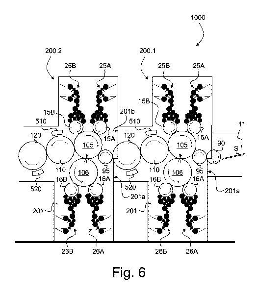
Such a configuration where at least two identical printing units 200.1, 200.2
are coupled
directly to one another is shown in the embodiment of Figure 6. Indeed, Figure
6 is a
schematic partial side view of a printing press designated by reference
numeral 1000 and
comprising at least two printing units 200.1, 200.2 of the same type as
previously
described in connection with Figure 5. Components 15A, 15B, 16A, 16B, 25A,
25B, 26A,
26B, 95, 105, 106, 110, 120, 201, 510, 520 in Figure 6 are the same components
as
described in connection with Figure 5 and do not therefore need to be
described again. It
suffices to understand that the two printing units 200.1, 200.2 are coupled
directly to one
another, with the second lateral side 201b of the first printing unit 200.1
being coupled to
the first lateral side 201a of the second printing unit 200.2. In the
illustration of Figure 6,
the first lateral side 201a of the first printing unit 200.1 is shown coupled
to a feeder table
1* of a sheet feeder, which feeder table 1* is provided with a sheet transfer
element 90 or
sheet transfer cylinder 90 acting as infeed and receiving individual sheets S
from e.g. a
swing-gripper arm system. The second lateral side 201b of the second printing
unit 200.2
(not shown in Figure 6) could likewise be coupled to a third printing unit in
a similar
manner to the first and second printing units 200.1, 200.2.
The last printing unit in the sequence of printing units could likewise be
coupled to any
suitable sheet conveying system for transporting the printed sheets S to a
corresponding
sheet delivery unit in a manner similar to what is shown e.g. in Figure 4, in
which case a
suitable sheet transfer element or sheet transfer cylinder could equally be
interposed
between the third sheet transfer element 120 or third sheet transfer cylinder
120 of the last
printing unit in the sequence and the upstream end of a sheet conveying system
3 (like
CA 03050613 2019-07-17
WO 2018/167064 PCT/EP2018/056247
19
the sheet transfer cylinder 13 depicted in Figure 4).
While this is not specifically illustrated, an inspection system similar to
the inspection
system 11, 12, 61, 62 shown in Figures 1 to 3 could likewise be provided
downstream of
the last printing unit with a view to inspect both sides of the printed sheets
S.
Figure 7 shows another embodiment of a printing press, designated by reference
numeral
1000*, according to the invention and comprising at least two printing units
200.1*, 200.2*
which are located one after the other. Like in the embodiment of Figure 6, an
uneven
number of sheet transfer elements, in particular sheet transfer cylinders,
namely transfer
cylinders 110, 120 and 95, is provided downstream of the printing nip of the
first printing
unit 200.1* and upstream of the printing nip of the second printing unit
200.2* to transfer
the sheets S from the first printing unit 200.1* to the second printing unit
200.2*. The only
difference with respect to the embodiment of Figure 6 resides in that not all
of the sheet
transfer elements 110, 120, 95 or sheet transfer cylinders 110, 120, 95 are an
integral part
of the first and second printing units 200.1*, 200.2*. Rather, in the example
of Figure 7,
only the first sheet transfer element 95 or sheet transfer cylinder 95 and the
second sheet
transfer element 110 or sheet transfer cylinders 110 are supported between the
pair of
side frames 201* of the two printing units 200.1*, 200.2*, the third sheet
transfer element
120 or sheet transfer cylinder 120 being supported in this case in an
intermediate frame
205 that is interposed between the second lateral side 201b* of the first
printing unit
200.1* and the first lateral side 201a9 of the second printing unit 200.2*. In
the illustrated
example, the second lateral side 201b* of the second printing unit 200.2* is
likewise
coupled to an intermediate frame 205 supporting the third sheet transfer
element 120 or
third sheet transfer cylinder 120 downstream of the second printing unit
200.2*.
From a functional perspective, components 1*, 15A, 15B, 16A, 16B, 25A, 25B,
26A, 26B,
90, 95, 105, 106, 110, 120, 201*, 205, 510, 520 in Figure 7 fulfill the same
function as
components 1*, 15A, 15B, 16A, 16B, 25A, 25B, 26A, 26B, 90, 95, 105, 106, 110,
120,
CA 03050613 2019-07-17
WO 2018/167064 PCT/EP2018/056247
201, 510, 520 described in connection with Figure 6.
Various modifications and/or improvements may be made to the above-described
embodiments without departing from the scope of the invention as defined by
the annexed
claims.
First of all, any one of the two printing cylinders 105, 106 could be designed
as a sheet
conveying cylinder and the invention is therefore not limited to the
illustrated embodiments
where the sheet conveying cylinder is located above the path of the sheets S.
The sheet
conveying cylinder could equally be located below the path of the sheets S. In
one
embodiment, the sheet conveying cylinder of a first printing unit is located
above the path
of the sheets S while a sheet conveying cylinder of an adjacent second
printing unit is
located below the path of the sheets S. In another embodiment, the sheet
conveying
cylinder of a first printing unit is located bellow the path of the sheets S
while a sheet
conveying cylinder of an adjacent second printing unit is located above the
path of the
sheets S.
Similarly, while Figures 6 and 7 show that three sheet transfer cylinders 110,
120, 95 are
provided downstream of the printing nip of the first printing unit 200.1,
respectively 200.1*,
and upstream of the printing nip of the second printing unit 200.2,
respectively 200.2*, to
ensure transfer of the sheets S from one printing unit to the other, any
number of at least
two sheet transfer elements or cylinders would be convenient. The number of at
least two
transfer elements or cylinders is preferably any uneven number of sheet
transfer elements
or cylinders and more preferably an uneven number of at least three sheet
transfer
elements or cylinders. The illustrated examples are advantageous in that the
at least two
sheet transfer elements 110, 120, 95 and in particular the at least three
sheet transfer
elements 110, 120, 95 or cylinders 110, 120, 95 ensure sufficient spacing
between two
successive printing units and accessibility to all relevant parts of the
printing presses, in
particular the plate cylinders 15A, 15B, 16A, 16B and drying/curing units 510,
520.
CA 03050613 2019-07-17
WO 2018/167064
PCT/EP2018/056247
21
Alternatively, the three sheet transfer elements 110, 120, 95 or cylinders
110, 120, 95
could be replaced by another number, in particular another uneven number of
sheet
transfer elements or cylinders, for example five sheet transfer cylinders of
the size as
sheet transfer cylinder 95 shown in Figure 6 and/or Figure 7.
It shall furthermore be appreciated that all relevant printing units do not
necessarily need
to be strictly identical. The embodiments disclosed herein however have a
major
advantage in that full modularity is ensured as each individual printing unit
is designed as
an elementary building block that can be added or removed from the printing
press
without major difficulties.
CA 03050613 2019-07-17
WO 2018/167064 PCT/EP2018/056247
22
LIST OF REFERENCE NUMERALS USED THEREIN
100 Simultan-type printing press ¨ (2+4)-over-(4) configuration (prior
art of
Figures 1 and 2)
100* Simultan-type printing press ¨ (2+4)-over-(2+4) configuration
(prior art of
Figure 3)
100** Double-decker-type printing press ¨ (4)-over-(4) configuration
(prior art of
Figure 4)
1000 printing press ¨ (2+2)-over-(2+2) configuration (embodiment of
Figure 6)
1000* printing press ¨ (2+2)-over-(2+2) configuration (embodiment of
Figure 7)
1 sheet feeder
1* feeder table
sheets
2 printing unit (prior art of Figures 1 and 2)
2* printing unit (prior art of Figure 3)
2.1-2.8 printing units (prior art of Figure 4)
200 printing unit (embodiment of Figure 5)
200.1, 200.2 printing units (embodiment of Figure 6)
200.1*, 200.2* printing units (embodiment of Figure 7)
3 sheet conveying system (chain gripper system with spaced-apart
gripper
bars)
31 pair of chain wheels of sheet conveying system 3 (upstream end)
4 sheet delivery unit
41, 42, 43 delivery pile units
sheet conveying cylinder / (first) printing cylinder (main printing group) /
three-segment blanket cylinder (Figures 1 to 3)
5.1-5.4 printing cylinders of printing units 2.1, 2.3, 2.5 and 2.7 / one-
segment
blanket cylinders (Figure 4)
CA 03050613 2019-07-17
WO 2018/167064 PCT/EP2018/056247
23
105 sheet conveying cylinder / (first) printing cylinder / two-segment
blanket
cylinder (embodiments of Figures 5 to 7)
6 (second) printing cylinder (main printing group) / three-segment
blanket
cylinder (Figures 1 to 3)
6.1-6.4 printing cylinders of printing units 2.2, 2.4, 2.6 and 2.8 / one-
segment
blanket cylinders (Figure 4)
106 (second) printing cylinder /two-segment blanket cylinder
(embodiments of
Figures 5 to 7)
7 sheet conveying cylinder / (third) printing cylinder (additional
printing
group) / two-segment blanket cylinder (Figure 3)
8 (fourth) printing cylinder (additional printing group) / two-
segment blanket
cylinder (Figures 1 to 3)
8' sheet conveying cylinder / two-segment cylinder (Figures 1 and 2)
9 sheet transfer cylinder (infeed ¨ Figures 1 to 4)
9', 9" sheet transfer cylinders (Figure 3)
90 sheet transfer cylinder (infeed ¨ embodiment of Figures 6 and 7)
95 (first) sheet transfer cylinder (embodiments of Figures 5 to 7)
sheet transfer cylinder (Figures 1 to 2)
10', 10", 10" sheet transfer cylinders (intermediate sheet conveying system
interposed
between additional printing group and main printing group ¨ Figure 3)
11 inspection cylinder or drum (part of inspection system ¨ Figures 1
to 3)
12 inspection cylinder or drum (part of inspection system ¨ Figures 1
to 3)
10.1-10.4 sheet conveying cylinders / impression cylinders of printing
units 2.1, 2.3,
2.5 and 2.7 / two-segment impression cylinders (Figure 4)
11.1-11.4 sheet conveying cylinders / impression cylinders of printing
units 2.2, 2.4,
2.6 and 2.8 / two-segment impression cylinders (Figure 4)
13 sheet transfer cylinder / two-segment cylinder (Figure 4)
110 (second) sheet transfer cylinder / two-segment cylinder
(embodiments of
Figures 5 to 7)
CA 03050613 2019-07-17
WO 2018/167064 PCT/EP2018/056247
24
120 (third) sheet transfer cylinder / two-segment cylinder
(embodiments of
Figures 5 to 7)
15 (four) plate cylinders cooperating with printing cylinder 5
(lower/verso side
of sheets S) / one-segment plate cylinders (Figures 1 to 3)
15.1-15.4 plate cylinders of printing units 2.1, 2.3, 2.5 and 2.7
(upper/recto side of
sheets S) / one-segment plate cylinders (Figure 4)
15A, 15B (two) plate cylinders of printing unit 200, 200.1, 200.2, 200.1*,
200.2*
(upper/recto side of sheets S) / one-segment plate cylinders (Figures 5 to
7)
16 (four) plate cylinders cooperating with printing cylinder 6
(upper/recto side
of sheets S) / one-segment plate cylinders (Figures 1 to 3)
16.1-16.4 plate cylinders of printing units 2.2, 2.4, 2.6 and 2.8
(lower/verso side of
sheets S) / one-segment plate cylinders (Figure 4)
16A, 16B (two) plate cylinders of printing unit 200, 200.1, 200.2, 200.1*,
200.2*
(lower/verso side of sheets S) / one-segment plate cylinders (Figures 5 to
7)
17 (two) plate cylinders cooperating with printing cylinder 7
(lower/verso side
of sheets S) / one-segment plate cylinders (Figure 3)
18 (two) plate cylinders cooperating with printing cylinder 8
(upper/recto side
of sheets S) / one-segment plate cylinders (Figures 1 to 3)
20 printing press main frame / pair of side frames (Figures 1 to 4)
201 frame of printing unit 200, 200.1, 200.2 / pair of side frames
(embodiments of Figures 5 and 6)
201a connection interface of frame 201 / first lateral side
(input/upstream side)
201b connection interface of frame 201 / second lateral side
(output/downstream side)
201* frame of printing unit 200.1*, 200.2* / pair of side frames
(embodiment of
Figure 7)
201a* connecting interface of frame 201* / first lateral side
(input/upstream side)
CA 03050613 2019-07-17
WO 2018/167064 PCT/EP2018/056247
201b* connecting interface of frame 201* / second lateral side
(output/downstream side)
205 intermediate frame (Figure 7)
21 retractable inking carriage supporting inking apparatuses 25
22 retractable inking carriage supporting inking apparatuses 26
23 retractable inking carriage supporting inking apparatuses 27
(Figure 3)
24 retractable inking carriage supporting inking apparatuses 28
(Figures 1 to
3)
25 (four) inking apparatuses each cooperating with a corresponding
one of
the plate cylinders 15 (Figures 1 to 3)
25.1-25.4 inking apparatus of printing units 2.1, 2.3, 2.5 and 2.7
cooperating with
plate cylinder 15.1, 15.2, 15.3, 15.4, respectively (Figure 4)
25A, 25B (two) inking apparatuses each cooperating with a corresponding one
of
the plate cylinders 15A, 15B (Figures 5 to 7)
26 (four) inking apparatuses each cooperating with a corresponding
one of
the plate cylinders 16 (Figures 1 to 3)
26.1-26.4 inking apparatus of printing units 2.2, 2.4, 2.6 and 2.8
cooperating with
plate cylinder 16.1, 16.2, 16.3, 16.4, respectively (Figure 4)
26A, 26B (two) inking apparatuses each cooperating with a corresponding one
of
the plate cylinders 16A, 16B (Figures 5 to 7)
27 (two) inking apparatuses each cooperating with a corresponding one
of
the plate cylinders 17 (Figure 3)
28 (two) inking apparatuses each cooperating with a corresponding one
of
the plate cylinders 18 (Figures 1 to 3)
50 drying/curing unit for recto side of sheets S, e.g. UV-LED curing
unit
(Figures 1 and 2)
51 (first) drying/curing unit for verso side of sheets S, e.g. UV-LED
curing
unit, cooperating with sheet transfer cylinder 10' (Figure 3)
CA 03050613 2019-07-17
WO 2018/167064 PCT/EP2018/056247
26
52 (second) drying/curing unit for recto side of sheets S, e.g. UV-
LED curing
unit, cooperating with sheet transfer cylinder 10" (Figure 3)
510 (first) drying/curing unit for recto side of sheets S, e.g. UV-LED
curing unit,
cooperating with sheet transfer cylinder 110 (embodiments of Figures 5 to
7)
520 (second) drying/curing unit for verso side of sheets S, e.g. UV-
LED curing
unit, cooperating with sheet transfer cylinder 120 (embodiments of
Figures 5 to 7)
61 inspection camera (verso side of sheets S) cooperating with
inspection
cylinder or drum 11, e.g. line-scan camera (Figures 1 to 3)
62 inspection camera (recto side of sheets S) cooperating with
inspection
cylinder or drum 12, e.g. line-scan camera (Figures 1 to 3)
Ti sheet transfer location to (first) sheet transfer cylinder 95 /
sheet input
location
T2 sheet transfer location away from (third) sheet transfer cylinder
120 /
sheet output location