Note: Descriptions are shown in the official language in which they were submitted.
SYSTEMS AND METHODS FOR REMOTE POWER TOOL DEVICE CONTROL
CROSS-REFERENCE TO RELATED APPLICATION
[0001] This application claims priority to U.S. Provisional Patent Application
No.
62/712,473 filed on July 31, 2018, the entire contents of which are hereby
incorporated by reference.
FIELD OF THE INVENTION
[0002] This application relates to controlling power tools with a mobile
device
through a battery pack of the power tool.
BRIEF DESCRIPTION OF THE SEVERAL VIEWS OF THE DRAWINGS
[0003] FIG. 1 is a communication system including a mobile device, a battery
pack,
and power tools.
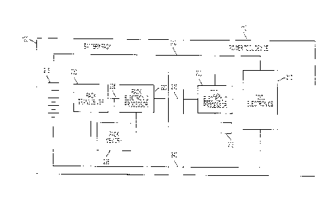
[0004] FIG. 2 is a block diagram of the battery pack and the power tool of
FIG. 1 in
accordance with some embodiments.
[0005] FIG. 3 is a block diagram of the mobile device of FIG. 1 in accordance
with
some embodiments.
[0006] FIG. 4 is a flowchart of a method for remotely controlling the power
tool
device of FIG. 1 in accordance with some embodiments.
[0007] FIG. 5 is a system for communication between a miter saw and a shop
vacuum
through battery packs and the mobile device in accordance with some
embodiments.
[0008] FIG. 6 is a flowchart of a method for automating dust collection during
operation of the miter saw of FIG. 5 in accordance with some embodiments.
DETAILED DESCRIPTION OF THE INVENTION
[0009] Before any embodiments of the invention are explained in detail, it is
to be
understood that the invention is not limited in its application to the details
of
CA 3050762 2019-07-29
construction and the arrangement of components set forth in the following
description
or illustrated in the following drawings. The invention is capable of other
embodiments and of being practiced or of being carried out in various ways.
[0010] One embodiment discloses a system for remote controlling a power tool
device. The system includes a battery pack coupled to a power tool device. The
battery pack includes a pack memory, a pack transceiver, and a pack electronic
processor. The pack electronic processor is coupled to the pack memory and the
pack
transceiver and is configured to determine that the power tool device is
remotely
controllable. The pack electronic processor is further configured to receive,
wirelessly via a pack transceiver of the battery pack, a remote control
command from
a mobile device, and to provide the remote control command to the power tool
device.
The system further includes a tool electronic processor of the power tool
device in
communication with the pack electronic processor. The tool electronic
processor is
configured to control the power tool device to perform an action specified by
the
remote control command in response to receiving the remote control command. In
some examples, the tool electronic processor is further configured to place
the power
tool device in a remote control mode in response to user input.
[0011] Another embodiment provides a method for remote controlling a power
tool
device. The power tool device is powered by a battery pack. The method
includes
determining, by a pack electronic processor of the battery pack, that the
power tool
device is remotely controllable and receiving, wirelessly via a pack
transceiver of the
battery pack, a remote control command from a mobile device. The method also
includes providing the remote control command, by the pack electronic
processor to
the tool electronic processor of the power tool device, and controlling, using
the tool
electronic processor, the power tool device to perform an action specified by
the
remote control command in response to the tool electronic processor receiving
the
remote control command. In some examples, the method further includes placing
the
power tool device in a remote control mode in response to user input.
[0012] Another embodiment provides a battery pack connectable to a power tool
device and configured to facilitate remote control of the power tool device by
a
mobile device. The battery pack includes a plurality of cells providing
operating
2
CA 3050762 2019-07-29
power to the power tool device, wherein the power tool device is coupled to
the
battery pack and a pack transceiver. The battery pack also includes a pack
electronic
processor electrically coupled to the transceiver. The pack electronic
processor is
further configured to determine that the connected power tool device is
remotely
controllable and receive, wirelessly via the pack transceiver, a remote
control
command from the mobile device. The pack electronic processor is also
configured to
provide, via a communication link between the pack electronic processor and a
tool
electronic processor of the power tool device, the remote control command. The
remote control command specifies an action to be performed by the power tool
device. In some examples, the power tool device performs the function
specified by
the remote control command in response to receiving the remote control
command.
[0013] FIG. 1 illustrates a communication system 100 including various power
tool
devices 110 powered by a battery pack 120. The system 100 also includes a
mobile
device 130 that can control the power tool devices 110 through the battery
pack 120.
The power tool devices 110 may include motorized power tool devices (for
example,
a miter saw 110A, a drill-driver 110B, a shop vacuum 110C, and the like) or
non-
motorized electrical devices (for example, a work radio 110D, a work light
110E, and
the like). Each of the power tool devices 110A-E may be individually referred
to as
the power tool device 110, or collectively as the power tool devices 110. At
least in
some embodiments, the power tool devices 110 may be described as electrically
powered devices that are configured to be coupled to and powered by a power
tool
battery pack (e.g., the battery pack 120) that is configured to be coupled to
and power
a motorized power tool (e.g., a drill, a saw, and the like).
[0014] The battery pack 120 is a power tool battery pack having a nominal
voltage of,
for example, 12 Volts, 18 Volts, and the like. The battery pack 120 includes a
housing 140, a tool interface 150, and a latch 160 controlled by actuator 170
to
selectively latch the tool interface 150 to a battery interface of the power
tool 110.
The mobile device 130 is a mobile communication device, for example, a smart
telephone, a tablet computer, a laptop computer, a personal digital assistant,
a smart
wearable device (e.g., smart watch), and the like.
3
CA 3050762 2019-07-29
[0015] With reference to FIG. 2, the power tool device 110 includes a tool
electronic
processor 200, a tool memory 205, and tool electronics 210. The tool
electronic
processor 200 may be implemented as, for example, a microprocessor, a
microcontroller, a field programmable gate array, an application specific
integrated
circuit, or the like. The tool memory 205 may be a part of the tool electronic
processor 200 or may be a separate component. The tool memory 205 may include,
for example, a program storage area and a data storage area. The tool memory
205
stores executable instructions that when executed by the tool electronic
processor 200,
cause the power tool device 110 to perform the functions described herein. For
example, the tool electronic processor 200 controls the functions of the power
tool
device 110 and enables communication between the power tool device 110 and the
battery pack 120. The tool electronics 210 may include a switch bridge and a
motor
(not shown) when the power tool device 110 is a motorized power tool and may
include other electronics (e.g., LEDs, radio transceiver, speaker, and the
like) when
the power tool device 110 is a non-motorized electronic device. The tool
electronics
210 are controlled by the tool electronic processor 200. For example, the tool
electronic processor 200 is configured to one or more of enable the tool
electronics
210, disable the tool electronics 210, and modify operating characteristics
(e.g., motor
power, LED brightness, radio tuning, speaker volume, and the like).
[0016] The battery pack 120 includes battery cells 215, a pack electronic
processor
220, a pack memory 225, and a pack transceiver 230 within the housing 140. The
pack electronic processor 220, the pack memory 225, and the pack transceiver
230
communicate over one or more control and or data buses (for example, a
communication bus 235). The battery cells 215 may be arranged in a series,
parallel,
or series-parallel combination. For example, the battery cells 215 include one
or more
series strings of five cells connected in parallel. In some embodiments, the
battery
cells 215 have a lithium-ion based chemistry and each provide approximately
3.6
nominal voltage. In other embodiments, the battery cells 215 have different
chemistry, voltage output, or both. The battery cells 215 provide operating
power to
4
CA 3050762 2019-07-29
the other components of the battery pack 120. Additionally, operating power
from the
battery cells 215 is provided to the power tool device 110 over power
terminals 240.
[0017] The pack electronic processor 220 may be implemented as, for example, a
microprocessor, a microcontroller, a field programmable gate array, an
application
specific integrated circuit, or the like. The pack memory 225 may be a part of
the
pack electronic processor 220 or may be a separate component. The pack memory
225 may include, for example, a program storage area and a data storage area.
The
pack memory 225 stores executable instructions that when executed by the pack
electronic processor 220, cause the battery pack 120 to perform the functions
described herein. The pack electronic processor 220 communicates with the tool
electronic processor 200 over a communication terminal 245 to exchange data
and
control signals. The communication terminals 245 may implement a serial
communication system for example, an RS-485 link or the like to facilitate
communications between the pack electronic processor 220 and the tool
electronic
processor 200. In some embodiments, rather than over the communication
terminal
245, the pack electronic processor 220 and the tool electronic processor 200
may
communicate over near-field wireless communication link, for example, a
Bluetooth
connection or the like. In such embodiments, the power tool device 110 and
battery
pack 120 include respective wireless transceivers to facilitate the wireless
communications.
[0018] The pack transceiver 230 facilitates communication between the battery
pack
120 and an external device, for example, the mobile device 130 over a wireless
communication network. In some embodiments, the pack transceiver 230 includes
a
combined transmitter-receiver component. In other embodiments, the pack
transceiver 230 includes separate transmitter and receiver components.
[0019] The power tool device 110 and the battery pack 120 may include more or
fewer components and may perform functions other than those described herein.
[0020] With reference to FIG. 3, the mobile device 130 includes a device
electronic
processor 310, a device memory 320, a device transceiver 330, and device
input/output interface 340. The device electronic processor 310, the device
memory
CA 3050762 2019-07-29
320, the device transceiver 330, and the device input/output interface 340
communicate over one or more control and/or data buses (for example, a
communication bus 350). The mobile device 130 may include more or fewer
components and may perform functions other than those described herein.
[0021] The device electronic processor 310 may be implemented as, for example,
a
microprocessor, a microcontroller, a field programmable gate array, an
application
specific integrated circuit, or the like. The device memory 320 may store
executable
instructions that are executed by the device electronic processor 310 to carry
out the
functionality of the mobile device 130 described herein.
[0022] The device transceiver 330 facilitates communication between the mobile
device 130 and an external device, for example, the battery pack 120 over a
wireless
communication network. In some embodiments, the device transceiver 330
includes a
combined transmitter-receiver component. In other embodiments, the device
transceiver 330 includes separate transmitter and receiver components. The
device
transceiver 330 is controlled by the device electronic processor 310, for
example, to
transmit and receive data between the mobile device 130 and the battery pack
120.
[0023] The device input/output interface 340 may include one or more input
mechanisms (e.g., a keypad, a mouse, and the like), one or more output
mechanisms
(e.g., a display, a speaker, and the like), or a combination of the two (e.g.,
a touch
screen, or the like).
[0024] The mobile device 130 also includes a mobile application 360, which is
an
application designed for a mobile operating system for use on the mobile
device 130.
The device memory 320 may store the mobile application 360 and the device
electronic processor 310 executes the mobile application 360 to enable the
mobile
device 130 to carry out the functionality of the mobile application 360
described
herein. The mobile application 360 may communicate with the battery pack 120
over
a connection between the mobile device 130 and the battery pack 120. The
mobile
application 360 may include a graphical user interface in that, execution of
the mobile
application 360 by the device electronic processor 310 may generate a
graphical user
interface on a display (e.g., input/output interface 340) of the mobile device
130. The
6
CA 3050762 2019-07-29
mobile device 130 may convey information to a user through display of the
graphical
user interface and may receive user input via the graphical user interface
(i.e., the
input/output interface 340).
[0025] In some embodiments, the mobile device 130 (via the device transceiver
330)
and the battery pack 120 (via the pack transceiver 230) communicate over a
direct
wireless connection, for example, a Bluetooth connection, a ZigBee
connection, or
the like. In other embodiments, the mobile device 130 (via the device
transceiver
330) and the battery pack 120 (via the pack transceiver 230) communicate over
an
indirect wireless connection, for example, over a cellular network, over the
Internet,
or the like.
[0026] FIG. 4 is a flowchart illustrating an exemplary method 400 for remotely
controlling the power tool device 110. As illustrated in FIG. 4, the method
400
includes placing the power tool device 110 in a remote control mode (at step
410).
The power tool device 110 may include a mode switch (not shown) that can be
actuated by a user to select a mode of the power tool device 110. For example,
the
mode switch may be between a first position for selecting the remote control
mode
and a second position for selecting a normal mode (i.e., deselecting the
remote control
mode) by the user. The tool electronic processor 200 receives position
information of
the mode switch and places the power tool device 110 in the selected mode.
Particularly, the tool electronic processor 200 determines that the mode
switch is in
the first position and places the power tool device 110 in the remote control
mode.
When the power tool device 110 is in the remote control mode, the power tool
device
110 can be remotely controlled by the mobile device 130 as described below.
When
the power tool device 110 is in the normal mode, the power tool device 110
ignores
(e.g., discards) commands received from the mobile device 130 without
executing the
received commands. However, the step 410 of placing the power tool device 110
in a
remote control mode is optional. For example, in some embodiments, the power
tool
device 110 may always be in a remote control mode such that the power tool
device
110 can be remotely controlled by the mobile device 130.
7
CA 3050762 2019-07-29
[0027] The method 400 also includes determining, by the pack electronic
processor
220, that the power tool device 110 is remotely controllable (at step 420).
The remote
control feature may not be provided on every power tool device 110 configured
to be
coupled to and powered by the battery pack 120. For example, the remote
control
feature may be provided on the work radio 110D, the work light 110E, and the
shop
vacuum 110C, but may not be provided on the miter saw 110A or the drill-driver
110B. In some embodiments, the pack electronic processor 220 determines
whether
the power tool device 110 is remotely controllable using identification
signals
received from the power tool device 110. For example, the tool electronic
processor
200 communicates identification signals over the communication terminal 245 to
the
pack electronic processor 220.
[0028] The identification signals may include for example, a type of the power
tool
(e.g., by model number), which is then used by the pack electronic processor
220 to
access and retrieve from a lookup table an indication of whether the power
tool device
110 is remotely controllable. The lookup table may be on the stored on the
pack
memory 225, the device memory 320, or a combination thereof In some
embodiments, the identification signals include an explicit indication of
whether the
power tool device 110 is remotely controllable or not remotely controllable.
[0029] In some embodiments, the battery pack 120 includes a sensor in
communication with the pack electronic processor 220 that is configured to
detect
whether the power tool device 110 is remotely controllable. For example, the
sensor
of the battery pack 120 may be a Hall effect sensor configured to detect a
magnetic
field, and the power tool device 110 that is remotely controllable may include
a
magnet near its battery pack interface. Upon coupling the power tool device
110 and
the battery pack 120, the sensor provides an output to the pack electronic
processor
220 indicative of the presence (or absence) of the magnet or indicative of the
pole
orientation of the magnet, and the output is indicative of whether the power
tool
device 110 is remotely controllable. Accordingly, power tool devices 110
having no
such magnet, or having a magnet with a pole orientation representing that the
device
is not remotely controllable, are determined by the pack electronic processor
220 to be
8
CA 3050762 2019-07-29
not remotely controllable. Power tool devices 110 having a magnet, or having a
magnet with a pole orientation representing that the device is remotely
controllable,
are determined by the pack electronic processor 220 to be remotely
controllable.
[0030] The method 400 further includes receiving, by the pack electronic
processor
220, a remote control command from the mobile device 130 (at step 430). The
remote control command can be a command to, for example, turn the power tool
device ON/OFF, activate a motor of the power tool device, switch an LED
ON/OFF,
adjust a radio station tuning, adjust an LED brightness, adjust a speaker
volume,
adjust a motor speed, and the like. The command can be selected on a graphical
user
interface of the mobile application 360. The battery pack 120 may communicate
the
type or identification information of the power tool device 110 connected to
the
battery pack 120 to the mobile device 130. The mobile device 130 may display a
list
of commands a user can select on the graphical user interface of the mobile
application 360. When the mobile device 130 receives a selection of the remote
control command from the list of commands (e.g., based on user input received
by the
device input/output interface 340), the mobile device 130 transmits the remote
control
command to the battery pack 120 via the device transceiver 330. Particularly,
the
pack electronic processor 220 receives the remote control command wirelessly
via the
pack transceiver 230.
[0031] The method also includes providing, by the pack electronic processor
220, the
remote control command to the tool electronic processor 200 of the power tool
device
110 (at step 440). The pack electronic processor 220 relays the command
received
from the mobile device 130 to the tool electronic processor 200. As described
above,
the pack electronic processor 220 and the tool electronic processor 200
communicate
over the communication terminal 245 or over a near-field communication link.
The
pack electronic processor 220 provides the remote control command to the tool
electronic processor 200 via the communication terminal 245 or the near-field
communication link. In some embodiments, the pack electronic processor 220 may
provide remote control command in response to determining that the power tool
9
CA 3050762 2019-07-29
device 110 is remotely controllable, that the power tool device 110 is in a
remote
control mode, or both.
[0032] The method 400 further includes controlling, by the tool electronic
processor
200, the power tool device 110 to perform an action specified by the remote
control
command (at step 450). The tool electronic processor 200, in response to
receiving
the remote control command, controls the tool electronics 210 to perform the
action
specified by the remote control command. For example, the tool electronic
processor
200 turns the power tool device ON/OFF, activates a motor of the power tool
device,
switches an LED ON/OFF, adjusts a radio station tuning, adjusts an LED
brightness,
adjusts a speaker volume, adjusts a motor speed, and the like. In some
embodiments,
the power tool device 110 operates in a lower power draw mode until a remote
control
command is received from the battery pack 120. In the low power draw mode, the
power draw is sufficient to maintain communication with the battery pack 120
and
monitor for remote control commands, but not sufficient to perform the actions
specified by the remote control command. Upon receiving the remote control
command, the tool electronic processor 200 switches the power tool device 110
to the
high power draw mode to perform the action specified by the remote control
command.
[0033] While the steps of the method 400 are illustrated in a particular
serial order, in
some embodiments, one or more of the steps are executed in parallel or in a
different
order than illustrated. For example, one or both of steps 410 and 420 may
occur in
parallel with or after step 430.
[0034] FIG. 5 illustrates one example system 500 for implementing a remote
controlling of power tool devices 110. The system 500 includes the miter saw
110A
(for example, a first power tool device) connected to a first battery pack
120A, the
shop vacuum 110C (for example, a second power tool device) connected to a
second
battery pack 120B, and the mobile device 130. The first battery pack 120A and
the
second battery pack 120B are examples of the battery pack 120 described above.
Accordingly, the description provided above with respect to the battery pack
120
similarly applies to the first battery pack 120A and the second battery pack
120B.
CA 3050762 2019-07-29
The mobile device 130 wirelessly communicates with the first battery pack 120A
and
the second battery pack 120B as described above.
[0035] When the miter saw 110A is operated on a workpiece, the resulting cut
may
create dust that is deposited on the work bench. Users may use the shop vacuum
110C to clear the dust deposited by the miter saw 110A. However, the user may
have
to pause the current cut to vacuum excess dust, or operate the vacuum between
successive cuts to clear dust. This dust removal may result in a user taking
additional
time to complete a project. In some embodiments, a hose 505 of the shop vacuum
110C is directly coupled to a dust port 510 of the miter saw 110A. The dust
port 510
includes a dust intake end 515 near the saw blade to extract dust during a cut
and a
dust exhaust end, opposite the dust intake end 515, to expel extracted dust
into the
hose 505 coupled to the dust port. Still, users may need to manually turn on
and off
the shop vacuum 110 with each cut, or leave the shop vacuum 110 enabled
between
cuts despite a lack of dust needing extraction between cuts.
[0036] The dust collection process can be automated to be more efficient and
to speed
up the project by remotely controlling the shop vacuum 110C while the miter
saw
110A is being operated. FIG. 6 is a flowchart illustrating an exemplary method
600
for automating dust collection during operation of a miter saw 110A. As
illustrated in
FIG. 6, the method 600 includes determining, by the device electronic
processor 310,
that the miter saw 110A (i.e., the first power tool device 110) is being
operated (at
step 610). For example, a pack electronic processor of the first battery pack
120A
detects a power draw when the user operates the miter saw 110A, for example,
using
a current sensor electrically connected to the power terminals of the first
battery pack
120A. The pack electronic processor of the first battery pack 120A sends a
signal, via
the pack transceiver, indicating that the miter saw 110A is being operated to
the
mobile device 130 in response to detecting the power draw. The device
electronic
processor 310 of the mobile device 130 determines that the miter saw 110A is
being
operated upon receiving this signal from the first battery pack 120A.
[0037] The method 600 also includes providing, by the device electronic
processor
310, a remote control command to the second battery pack 120B in response to
the
11
CA 3050762 2019-07-29
determination that the miter saw 110A is being operated (at step 620). For
example,
in response to determining that the miter saw 110A is being operated, the
device
electronic processor 310 transmits the remote control command via the device
transceiver 330, and the remote command is received by the second battery pack
120B. The remote control command is a request to turn the shop vacuum 110C
(i.e.,
the second power tool 110) ON (i.e., to activate a motor of the shop vacuum
110C).
[0038] The method further includes controlling the shop vacuum to turn ON in
response to the remote control command received by the second battery pack
120B (at
step 630). For example, the pack electronic processor 220 of the second
battery pack
120B relays the remote control command to the tool electronic processor 200 of
the
shop vacuum 110C. In response to the remote control command, the tool
electronic
processor 200 of the shop vacuum 110C switches the shop vacuum 110 from the
low
power draw mode to the high power draw mode and activates the motor of the
shop
vacuum 110C. Accordingly, the shop vacuum 110C may be operated essentially
simultaneously with the miter saw 110A without any user intervention. In other
words, when the miter saw 110A is activated by the user, the shop vacuum 110C
is
activated. This allows the dust collection process to be automated, which
saves time
for the user and provided a more efficient dust extraction.
[0039] In some embodiments, a similar technique is used to deactivate the shop
vacuum 110C in response to deactivation of the miter saw 110 by the user. For
example, after step 630, the device electronic processor 310 determines that
the miter
saw 110A (i.e., the first power tool device 110) has ceased being operated.
For
example, the pack electronic processor 220 of the first battery pack 120A
detects a
lack of power draw by the miter saw 110A in response to the user releasing a
trigger
of the saw. In turn, the pack electronic processor 220 of the first battery
pack 120A
sends a signal, via the pack transceiver, indicating that the miter saw 110A
has ceased
being operated to the mobile device. In response to receiving the signal, the
device
electronic processor 310 of the mobile device 130 determines that the miter
saw 110A
has ceased being operated.
12
CA 3050762 2019-07-29
[0040] Further, the device electronic processor 310 provides a second remote
control
command to the second battery pack 120B in response to the determination that
the
miter saw 110A has ceased being operated. For example, in response to
determining
that the miter saw 110A has ceased being operated, the device electronic
processor
310 transmits the second remote control command via the device transceiver
330, and
the second remote command is received by the second battery pack 120B. The
second remote control command is a request to turn the shop vacuum 110C (i.e.,
the
second power tool 110) OFF (i.e., to deactivate a motor of the shop vacuum
110C).
[0041] Further, the shop vacuum is controlled to turn OFF in response to the
second
remote control command received by the second battery pack 120B. For example,
the
pack electronic processor 220 of the second battery pack 120B relays the
second
remote control command to the tool electronic processor 200 of the shop vacuum
110C. In response to the remote control command, the tool electronic processor
200
of the shop vacuum 110C switches the shop vacuum 110 from the high power draw
mode to the low power draw mode and deactivates the motor of the shop vacuum
110C. Accordingly, the shop vacuum 110C may be enabled and disabled
essentially
simultaneously with the miter saw 110A without any user intervention. In other
words, when the miter saw 110A is activated by the user, the shop vacuum 110C
is
activated, and when the miter saw 110A is deactivated by the user, the shop
vacuum
110C is deactivated. This allows the dust collection process to be automated,
which
saves time for the user and provided a more efficient dust extraction.
[0042] In some embodiments, the first battery pack 120A and the second battery
pack
120B communicate directly bypassing the mobile device 130. The mobile device
130
may be used to communicatively connect the first battery pack 120A and the
second
battery pack 120B. The mobile device 130 may be used to pair (for example,
Bluetooth pairing) the first battery pack 120A with the second battery pack
120B.
For example, a connection may be initiated using a graphical user interface
(GUI) of a
software application executing on the mobile device 130. In this example, the
mobile
device 130 may detect that the battery packs 120A, 120B in wireless
communication
range; display an identifier for the battery packs 120A, 120B on the GUI; and
allow a
13
CA 3050762 2019-07-29
user to select on the GUI the first battery pack 120 and the second battery
pack 120B
for pairing with each another. To pair the first battery pack 120A with the
second
battery pack 120B, the mobile device 130 may provide identification
information,
connection identification information, and/or password information for the
connection
to each of the first battery pack 120A and the second battery pack 120B. The
first
battery pack 120A and the second battery pack 120B use the identification
information, connection information, and/or password information to
subsequently
establish a communication link or to communicate with each other.
Particularly, the
first battery pack 120A and the second battery pack 120B communicate directly
to
implement the method 600 as provided above.
[0043] Thus, embodiments described herein provide, among other things, a
system
and method for remote control of a power tool device.
14
CA 3050762 2019-07-29