Note: Descriptions are shown in the official language in which they were submitted.
CA 03051698 2019-07-25
WO 2018/148299
PCT/US2018/017250
- 1 -
PROTECTIVE PACKAGING STRUCTURE
FOR COMPRESSIBLE MATERIALS
CROSS-REFERENCE TO RELATED APPLICATIONS
This application claims benefit of U.S. Provisional No. 62/456,180 filed
February 8, 2017 and entitled "PROTECTIVE PACKAGING STRUCTURE FOR
COMPRESSIBLE MATERIALS," the contents of which are incorporated in their
entirety by reference.
TECHNICAL FIELD
The present disclosure relates to packaging structures for the storage or
transportation of materials sensitive to shock, vibration, deformation, or
separation
from agitation. More specifically, the present disclosure relates to storage
containers
and packaging methods for the storage or transportation of compressible
biologically
active materials. Even more specifically, these storage containers and the
associated
packaging methods protect the compressible biologically active materials,
which may
include composite fibers and granules, from shock, vibration, deformation, or
separation from agitation during storage and while being transported.
BACKGROUND
Over the past decade, there have been many new advancements in the field of
tissue regeneration and wound care. One such advancement is in the area of
materials
science and the development of novel synthetic graft materials that include
biologically active ceramics and glass. Today, biologically active glass
products in
fiber form are available for tissue scaffolding, and have shown great
potential in their
ability to help regrow new tissue, including both soft tissue and hard, bone
tissue, as
well as for wound dressings. While clinical outcomes have been favorable, the
fragile
CA 03051698 2019-07-25
WO 2018/148299
PCT/US2018/017250
- 2 -
and specifically compressible nature of the products themselves presents a
unique
challenge in terms of handling, and particularly with storage and
transportation.
It is well accepted that the packaging of medical devices is just as critical
as
the devices themselves. Besides the very fundamental requirement to maintain
the
sterility of the device, superior medical technology cannot be delivered if
the medical
device arrives damaged. Particularly with compressible synthetic fiber
materials for
wound care and tissue regeneration, maintaining the integrity of these
materials
during transportation is critical for ensuring the product meets the
advertised product
specifications and the customer expectations after shipping. Glass fiber
materials,
especially uncoated, will compress and change shape under its own weight if
stored in
standard packaging arrangements such as a standard plastic tray sealed with a
Tyvek
or foil lid, or a plastic clamshell container. Vibrations from normal shipping
activities
can lead to shifting of the fibers in the package, which can lead to
alterations in the
shape, appearance, and function of the fibrous synthetic product. The shape
change is
especially critical for wound dressings in the same shelf box in that
significant
product variation from dressing to dressing leads to loss in customer
confidence.
Accordingly, it is desirable to provide improved containers that serve to
maintain the integrity of the fibrous synthetic materials during storage and
especially
during transportation. These containers should be able to protect the
materials from
shock, vibration, deformation, or separation from agitation.
CA 03051698 2019-07-25
WO 2018/148299
PCT/US2018/017250
- 3 -
BRIEF SUMMARY
The present disclosure provides a more robust packaging structure for
maintaining the integrity of biologically active materials during storage and
especially
during transportation. These containers protect the materials from shock,
vibration,
deformation, or separation from agitation. The materials may be in the form of
synthetic fibers, and may include a composite of fibers and beads or granules.
According to one aspect of the disclosure, suitable materials that may benefit
from
such a robust packaging structure include synthetic materials that comprise a
biologically active ceramic or glass.
In one exemplary embodiment of the present disclosure, a protective
packaging structure for transporting compressible materials is provided. The
protective packaging structure may comprise a containment unit having a first,
lower
shell and a second, upper shell. The first, lower shell may include one or
more wells
for receiving a compressible material therein, each of the one or more wells
having a
surface feature to facilitate containment and reduce movement of the
compressible
material within the one or more wells. The second, upper shell may be
configured to
nest against the first, lower shell to form a closed container. The upper
shell may
further have one or more raised portions for defining discrete geometries of
the
compressible material.
According to one aspect of the disclosure, the closed container may be
configured to exert a compressive force against the compressive material
within, and
protect the compressive material from shock, vibration, deformation, or
separation
from agitation, when inside the closed container.
According to another aspect of the disclosure, the compressive force may be a
vacuum force or a mechanical force. The containment unit may be configured to
provide a gradient of pressure across its surface, such that different
pressures are
exerted against the material residing within the containment unit from one
region to
another, and across the surface area of the material.
CA 03051698 2019-07-25
WO 2018/148299
PCT/US2018/017250
- 4 -
Further, the containment unit may include various surface features on either
the upper or lower part of the containment unit to assist in maintaining the
position of
the material and reduce or eliminate any shifting within the containment unit,
as well
as to provide visual cues for the clinician to measure, cut or otherwise shape
the
material for clinical use.
In one embodiment, the packaging structure may comprise a containment unit
having two wells. In another embodiment, the packaging structure may comprise
a
containment unit having four wells.
In one embodiment, the packaging structure may comprise first and second
shells that are separate components and configured to snap onto one another.
In
another embodiment, the packaging structure may comprise first and second
shells
that are connected on one side to form a clamshell.
According to one aspect of the disclosure, at least one of the shells may be
formed of a clear material for visualization of the compressible material
therein.
According to another aspect, the second, upper shell may be configured to
screw onto
the first, lower shell. For instance, in one example, the first and second
shells may be
cylindrical, circular or otherwise round, and include threads to interlock
together.
According to still another aspect of the disclosure, the second, upper shell
may
include a handle.
In one embodiment, the first, lower shell may include surface features
comprising spikes, barbs, bumps, ridges, teeth, an etched surface or a
roughened
surface. The surface feature of the first, lower shell may reside on a bottom
surface of
the shell, or on a side surface of the shell.
According to one aspect of the disclosure, the first and second shells may be
configured to form a re-closeable seal when attached together. According to
another
aspect of the disclosure, one or more raised portions on the second, upper
shell may
create hatch marks within which are square or rectangular geometries. The
first and
second shells may be configured to form a mold tray for the compressible
material
when attached together.
CA 03051698 2019-07-25
WO 2018/148299
PCT/US2018/017250
- 5 -
According to one aspect of the disclosure, the packaging structure may be
useful for compressible materials that comprise a porous, fibrous and
hydrophilic
biologically active material. According to another aspect of the disclosure,
the sealed
container may be configured to prevent gases, liquids and debris from passing
therethrough.
According to one aspect of the disclosure, the thickness of the first, lower
shell or the second, upper shell may be non-uniform throughout. According to
another aspect of the disclosure, the surface feature of the first, lower
shell may be
uniformly distributed throughout the bottom surface of the shell. According to
still
another aspect of the disclosure, the surface feature may create visual
cutting guides
for cutting the compressible material, and/or may create visual measurement
guides
for measuring a size of the compressible material.
In one exemplary embodiment, the surface feature of the first, lower shell may
comprise uniformly sized features, while in another exemplary embodiment, the
surface feature of the first, lower shell may comprise non-uniformly sized
features.
According to one aspect of the disclosure, the packaging structure creates a
sealed container may be configured to provide a gradient of compression force
throughout. According to another aspect of the disclosure, the packaging
structure
may be configured to maintain the compressible material in a sterile condition
when
sealed.
In another exemplary embodiment of the present disclosure, a kit for tissue
repair is provided. The kit may comprise a compressible composition of
biologically
active glass fibers and beads, and a protective packaging structure for
transporting the
composition. The protective packaging structure may comprise a containment
unit
having a first, lower shell and a second, upper shell. The first, lower shell
may
include one or more wells for receiving a compressible material therein, each
of the
one or more wells having a surface feature to facilitate containment and
reduce
movement of the compressible material within the one or more wells. The
second,
upper shell may be configured to nest against the first, lower shell to form a
closed
CA 03051698 2019-07-25
WO 2018/148299
PCT/US2018/017250
- 6 -
container. The upper shell may further have one or more raised portions for
defining
discrete geometries of the compressible material.
According to one aspect of the kit, the closed container may be configured to
exert a compressive force against the compressive material within, and protect
the
compressive material from shock, vibration, deformation, or separation from
agitation, when inside the closed container.
According to another aspect of the kit, the compressive force may be a
vacuum force or a mechanical force. The containment unit may be configured to
provide a gradient of pressure across its surface, such that different
pressures are
exerted against the material residing within the containment unit from one
region to
another, and across the surface area of the material.
Further, the containment unit may include various surface features on either
the upper or lower part of the containment unit to assist in maintaining the
position of
the material and reduce or eliminate any shifting within the containment unit,
as well
as to provide visual cues for the clinician to measure, cut or otherwise shape
the
material for clinical use.
In one embodiment, the packaging structure may comprise a containment unit
having two wells. In another embodiment, the packaging structure may comprise
a
containment unit having four wells.
In one embodiment, the packaging structure may comprise first and second
shells that are separate components and configured to snap onto one another.
In
another embodiment, the packaging structure may comprise first and second
shells
that are connected on one side to form a clamshell.
According to one aspect of the kit, at least one of the shells may be formed
of
a clear material for visualization of the compressible material therein.
According to
another aspect, the second, upper shell may be configured to screw onto the
first,
lower shell. For instance, in one example, the first and second shells may be
cylindrical, circular or otherwise round, and include threads to interlock
together.
CA 03051698 2019-07-25
WO 2018/148299
PCT/US2018/017250
- 7 -
According to still another aspect of the disclosure, the second, upper shell
may
include a handle.
In one embodiment, the first, lower shell may include surface features
comprising spikes, barbs, bumps, ridges, teeth, an etched surface or a
roughened
surface. The surface feature of the first, lower shell may reside on a bottom
surface of
the shell, or on a side surface of the shell.
According to one aspect of the kit, the first and second shells may be
configured to form a re-closeable seal when attached together. According to
another
aspect of the kit, one or more raised portions on the second, upper shell may
create
hatch marks within which are square or rectangular geometries. The first and
second
shells may be configured to form a mold tray for the compressible material
when
attached together.
According to one aspect of the kit, the protective packaging structure may be
useful for compressible materials that comprise a porous, fibrous and
hydrophilic
biologically active material. According to another aspect of the kit, the
sealed
container may be configured to prevent gases, liquids and debris from passing
therethrough.
According to one aspect of the kit, the thickness of the first, lower shell or
the
second, upper shell may be non-uniform throughout. According to another aspect
of
the kit, the surface feature of the first, lower shell may be uniformly
distributed
throughout the bottom surface of the shell. According to still another aspect
of the
kit, the surface feature may create visual cutting guides for cutting the
compressible
material, and/or may create visual measurement guides for measuring a size of
the
compressible material.
In one exemplary embodiment, the surface feature of the first, lower shell may
comprise uniformly sized features, while in another exemplary embodiment, the
surface feature of the first, lower shell may comprise non-uniformly sized
features.
CA 03051698 2019-07-25
WO 2018/148299
PCT/US2018/017250
- 8 -
According to one aspect of the kit, the protective packaging structure may
create a sealed container configured to provide a gradient of compression
force
throughout. According to another aspect of the kit, the protective packaging
structure
may be configured to maintain the compressible material in a sterile condition
when
sealed.
It is to be understood that both the foregoing general description and the
following detailed description are exemplary and explanatory only and are not
restrictive of the disclosure. Additional features of the disclosure will be
set forth in
part in the description which follows or may be learned by practice of the
disclosure.
CA 03051698 2019-07-25
WO 2018/148299
PCT/US2018/017250
- 9 -
BRIEF DESCRIPTION OF THE DRAWINGS
The accompanying drawings, which are incorporated in and constitute a part
of this specification, illustrate several embodiments of the disclosure and
together
with the description, serve to explain the principles of the disclosure.
FIGS. 1A, 1B and 1C are photographs of prior art packaging structures
containing glass fiber wound care dressings after shipment.
FIG. 2 is another photograph of a prior art packaging structure containing a
glass fiber wound care dressing after shipment.
FIG. 3 is a photograph of an exemplary embodiment of a packaging structure
of the present disclosure containing a glass fiber wound care dressing.
FIGS. 4A and 4B illustrate another exemplary embodiment of a packaging
structure of the present disclosure, in which FIG. 4A shows a top-down view of
a
lower shell, while FIG. 4B illustrates a top-down view of an upper lid for use
with the
lower shell of FIG. 4A.
FIGS. 5A and 5B are photographs of the packaging structure of FIGS. 4A and
4B containing a glass fiber wound care dressing, in which FIG. 5A shows a
photograph of the packaging structure and glass fiber wound care dressing in a
closed
state, while FIG. 5B shows a photograph of the glass fiber wound care dressing
removed from the packaging structure of FIG. 5A.
FIG. 6 is a cross-sectional view of still another exemplary embodiment of a
packaging structure of the present disclosure containing a glass fiber
material.
FIG. 7 is a cross-sectional view of yet another exemplary embodiment of a
packaging structure of the present disclosure having a gradient of compression
forces.
FIG. 8 is a cross-sectional view of even still another exemplary embodiment
of a packaging structure of the present disclosure having a gradient of
compression
forces.
CA 03051698 2019-07-25
WO 2018/148299
PCT/US2018/017250
- 10 -
DETAILED DESCRIPTION
The present disclosure provides a more robust packaging structure for
maintaining the integrity of biologically active materials during storage and
especially
during transportation. These containers protect the materials from shock,
vibration,
deformation, or separation from agitation. The materials may be in the form of
synthetic fibers, and may include a composite of fibers and beads or granules.
In
some embodiments, the materials may comprise a biologically active ceramic or
glass. For example, fibrous composite materials of the type described in U.S.
Patent
No. 8,173,154, U.S. Patent No. 8,535,710, and U.S. Patent No. 8,821,919 may
benefit
from the use of the various packaging structures of the present disclosure.
The improvements in fiber packaging provided in this disclosure allow for
more rigorous handling prior to use. Since the vibration of normal shipping
and
handling have now been addressed with the improved fiber packaging, new
applications of the material are now possible. The fiber material may now be
utilized
by individuals such as first responders or military personal located in-
theater or at
forward military positions. The new compression packaging can give the fibers
the
capability of handling shocks and vibration on a regular basis while being
carried in a
soldier's backpack or riding on rough terrain in a vehicle.
Immobilization of synthetic fibers, particularly compressible synthetic fiber
materials comprising bioactive glass or ceramic for wound care dressing and
tissue
regeneration, is critical for ensuring the product meets the advertised
product
specifications and the customer expectations after shipping. Glass fiber
materials,
especially uncoated, will compress and change shape under its own weight if
stored in
standard packaging arrangements such as a standard plastic tray sealed with a
Tyvek
or foil lid, or a plastic clamshell container. Vibrations from normal shipping
activities
can lead to shifting of the fiber in the package, which can lead to
alterations in the
shape, appearance, and function of the wound care product. The shape change is
especially critical for dressings in the same shelf box, in that significant
product
variation from dressing to dressing leads to loss in customer confidence.
CA 03051698 2019-07-25
WO 2018/148299
PCT/US2018/017250
- 11 -
Turning now to the illustrations, FIGS. 1A, 1B and 1C represent photographs
of three individual glass fiber dressings 100 stored in single-unit containers
2 of the
prior art that were pulled from a single shelf box after standard shipping.
Meaning,
each of the single-unit containers 2 were shipped together in the same box. As
clearly
shown in the photographs, the range in appearance and size of the contents
varies
from one container 2 to the next, even though these containers 2 were shipped
at the
same time and in the same box. The left unit (FIG. 1A) shows approximately
100%
fill, while the middle unit (FIG. 1B) shows approximately 90% fill, and the
right unit
(FIG. 1C) shows approximately 75% fill. In addition, there are noticeable
creases and
folds forming in the dressing 100 of FIG. 1C on the right. Further, there is
evidence
of the fiber material separating or breaking down, as visible in the same
dressing 100
of FIG. 1C. Thus, it is clear that each of the three dressings 100 contained
within the
single-unit containers 2 of FIGS. 1A, 1B and 1C are of noticeably different
size and
have varying levels of folds or creases, despite having the same content
(including
content size and volume) at shipment, and were shipped together at the same
time.
As FIG. 2 further illustrates, the presence of free flowing beads 102 that
have
separated from the dressing 100 and amassed in the bottom left corner of the
prior art
container 2 represents another significant problem with the prior art
packaging today.
There is minimal compression provided by the Tyvek lid closing the holding
tray of
the prior art container 2, and even a plastic clamshell-type design offers
minimal
compression after the initial closure. When the container undergoes agitation
or
shock during transportation, the jostling action can cause the fiber
materials, some of
which are composites of fibers and beads of bioactive glass, to separate much
in the
way a centrifuge would cause separation of a mixture of different components
of
different densities.
To overcome these problems with currently existing packaging, the present
disclosure provides a more robust packaging structure 10 for maintaining the
integrity
of compressible, biologically active materials 100 during storage and
especially
during transportation. These containers 10 protect the materials 100 from
shock,
vibration, deformation, or separation from agitation. According to one aspect
of the
CA 03051698 2019-07-25
WO 2018/148299
PCT/US2018/017250
- 12 -
disclosure, one solution is to hold the dressing in a constant state of
compression to
ensure that the dressing does not change shape or lose function during
shipping.
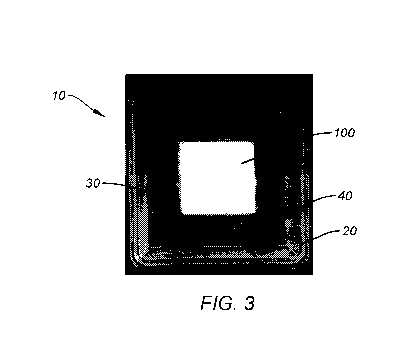
In one exemplary embodiment illustrated in FIG. 3, the packaging structure 10
may comprise a first, lower shell or tray 20 and a second, upper shell or lid
40. The
first, lower shell 20 may be defined by a bottom surface 22 surrounded by
sidewalls
24, and include one or more wells 30 for receiving a compressible material 100
such
as a fibrous bioactive glass material for wound care dressing or tissue
regeneration.
The second, upper shell 40 may be defined by a top surface 42 surrounded by
sidewalls 44 and be configured to nest against the first, lower shell 20 to
form a
closed container. According to one aspect of the disclosure, the closed
container may
be configured to exert a compressive force against the compressive material
within,
and protect the compressive material 100 from shock, vibration, deformation,
or
separation from agitation, when inside the closed container 10. The
compressive
force may be a vacuum force or a mechanical force, as will be described in
detail
below.
The packaging structure 10 illustrated in FIG. 3 comprises a two piece shell
design that snaps together, putting the fiber dressing 100 into a state of
compression.
Compression may be achieved by forming a pad of fiber with a bulk density of
¨5g/in3. As shown, the two pieces of the packaging structure 10 may be
separate
components that are configured to snap together or interlock. Of course, it is
understood that the two pieces may also share a common side, or connect at one
edge,
in order to form a clamshell-type containment unit. It is also contemplated
that the
shells 20, 40 may include threads 32, and be configured to screw together, the
upper
shell being able to screw onto the bottom shell in an interlocking connection,
for
example, as shown in the exemplary embodiment in FIG. 6. The shells 20, 40
themselves may be round in shape. If so desired, the upper shell 40 may also
include
a lip or handle 46 for ease of handling (see Figure 6). Likewise, the lower
shell 20
may have a lip, flange or other gripping portion 26 for convenient handling.
In some
embodiments, the packaging structure 10 may be re-sealable, and the first and
second
shells 20, 40 can form a re-closeable seal when attached together. In other
CA 03051698 2019-07-25
WO 2018/148299
PCT/US2018/017250
- 13 -
embodiments, the packaging structure 10 may be configured to maintain
sterility of
its contents until the seal is broken, and would therefore not be resealable.
As shown in the exemplary embodiment of FIG. 3, the lower tray 20 may
comprise one single well 30 for a single unit dressing or pad 100. However, it
is
understood that the tray 20 may comprise more than one well 30, and for
example,
may comprise two or four wells, as will be shown in other examples herein. In
one
embodiment, the well 30 may measure approximately 2 inches x 2 inches and form
a
square shape. However, other shapes and sizes are also contemplated for the
well,
such as for example, a rectangle or circle.
Moreover, one or more of the shells 20, 40 may be formed of a clear or
transparent material so that the contents are clearly visible. The packaging
structure
10 shown in FIG. 3 comprises a lower and upper shells (or tray and lid) 20,
40, both
of which are formed of a clear material for visualization of the compressible
material
100 within. Each of the shells 20, 40 may be formed of a plastic material and
configured to prevent gases, liquids and debris from getting into the well 30
and
contaminating or damaging the materials 100, which may be porous and/or
hydrophilic and therefore susceptible to moisture or humidity.
The packaging structure of FIG. 3 provides a compressive force against the
material 100 in the range of about 5g/in3, for example. This compressive force
is
created when the upper and lower shells 20, 40 come together and create a
mechanical force or pressure that is exerted against the compressible material
100
contained within it. Alternatively, or in addition, a vacuum force may also be
utilized
to create the compressive force. Accordingly, the containment unit or
packaging
structure can be considered to act like a mold tray.
In the exemplary embodiment of FIG. 3, both shells 20, 40 of the packaging
structure 10 are smooth. In other embodiments, however, one or more of the
shells
20, 40 may not be smooth. In addition to the immobilization of the fibrous
material
100 that comes from the shells 20, 40 once pressed together, dimensional
features
molded into the plastic shells 20, 40 may enhance the immobilization by adding
additional compression to the dressing or materials 100. In some embodiments,
each
CA 03051698 2019-07-25
WO 2018/148299
PCT/US2018/017250
- 14 -
of the wells 30 of the shells 20 may have a surface feature to facilitate
containment
and reduce movement of the compressible material 100 within the wells. For
instance, patterns molded in the top and bottom of the shells 20 40 act as
teeth to
impart a gripping characteristic to the otherwise smooth plastic surface.
As an example, FIGS. 4A and 4B illustrate another exemplary embodiment of
a packaging structure 110. Packaging structure 110 shares the same features of
packaging structure 10, with like reference numerals representing the same
features.
FIG. 4B shows a raised surface forming a cross pattern 48 in the top surface
42 of
upper shell or lid 40, while FIG. 4A shows a raised surface forming a dimpled
array
28 in the bottom surface 22 of lower shell or tray 20. The added compression
features
28, 48 in the shells 20, 40 reduce the movement of the dressing 100 during
shipment
with no noticeable change in dimensions or loss of beads 102 from the fiber
matrix
material 100. Another embodiment may have a raised surface pattern covering
some
or the entire top and/or bottom surface of each shell 20, 40, in order to add
surface
attachment enhancement or grip across the entire fiber dressing 100, rather
than a flat
surface. It is envisioned that any feature that imparts a force in a localized
area may
be incorporated into the embodiments described herein. For instance, another
embodiment may use both the patterns and the textured surface.
Suitable compression or surface features can include, for example, spikes,
barbs, bumps, ridges, teeth, etchings or surface roughenings. These surface
features
can be found on the bottom of the first, lower shell 20. However, the surface
features
may also be provided on the side surfaces 24 or of the well 30, as well as on
the
second, upper shell 40. The compression features of the packaging structure 10
of
FIGS. 4A and 4B are uniformly distributed across the bottom of the lower shell
20.
In the example shown, the dimples 28 are uniformly spaced apart about 0.5
inches
from one another. However, it is contemplated that in other embodiments the
compression features may be arranged in a non-uniform array or pattern, in
order to
provide a gradient of compressive forces across the packaging structure 10.
For
instance, the compression features may be arranged in a starburst pattern,
with a
greater concentration of the features in the center, as the features radiate
outwards to
the edges. In another embodiment, the compression features may be all
uniformly
CA 03051698 2019-07-25
WO 2018/148299
PCT/US2018/017250
- 15 -
sized. In still another embodiment, the compression features may be
differently sized
relative to one another, to create a non-uniform compression force within the
packaging structure 20. Still in other embodiments, the type or shape or style
of
compression features may be non-uniform such that a combination of different
features can be utilized on the same shell, such as for example, a combination
of
dimples and etchings either uniformly or non-uniformly arranged across the
shells 20,
40.
In another aspect of the disclosure, certain features of the fiber
immobilization
system can additionally aid the clinician in application of the dressing. As
an
example, as shown in FIG. 4B, the upper shell or lid 40 may have one or more
raised
portions 48 for defining discrete geometries of the compressible material. For
instance, these raised portions create hatch marks 48 such that, when used
with the
compressible material as shown in FIG. 5A, the cross pattern of raised
portions 48
built into the top piece of the packaging structure 10 actually can impart
some
indentations into the dressing 100 that make separating the material 100 into
four (4)
2x2 dressings or squares of material simpler, and eliminates the need for
scissors.
These hatch marks 48 can define discrete geometries such as a square or
rectangular
shape, and as shown, can provide indentation marks on the material 100 that
serves to
score the material for ease of separation. FIG. 5B shows how the material is
easily
separated into these discrete geometries without requiring cutting tools. In
this way,
the packaging structure 10 of the present disclosure also serves as a molding
tray,
allowing the materials 100 to be maintained in a defined shape during storage
and
transportation until its use.
As shown, the hatch marks 48 can create distinct squares of materials for use
as dressing or tissue scaffolds. However, other configurations of indentations
could
be used, but the concept is the same for adding functionality by immobilizing
the
dressing until use, and allowing the clinician to more easily conform the
dressing to
the needs of the patient. Additionally, the dimples 28 formed at the bottom of
the
dressing would allow the clinician to have a visual measurement tool as well
as a
cutting guide for cutting shapes that are not defined by the top cross hatch
48. For
example, for a wound that was 2.5" in length, a dimple array of 0.5 inches
would
CA 03051698 2019-07-25
WO 2018/148299
PCT/US2018/017250
- 16 -
allow the clinician to simply count out 5 of the dimples and cut, as opposed
to trying
to measure and somehow mark the dressing before cutting. These additions save
time
for the clinician and increase value, especially in surgery where time is
critical.
The packaging structures of the present disclosure may be configured to
provide compression of the fiber material to an average volumetric density in
the
range of: about 0.5g/in3 to 20g/in3, or about 1g/in3 to 10g/in3, or even about
2g/in3 to
5g/in3. As represented in FIG. 6, in another exemplary embodiment the
packaging
structure 210 may provide uniform compression force against the fiber material
100
contained within it. This can be accomplished with a packaging structure 210
employing threads 32 to allow the upper shell 40 to secure onto the lower
shell 20,
and exert an even, uniform force onto the contained material 100 once the two
shells
20, 40 are locked together.
However, in another aspect of the present disclosure, the packaging structures
may be configured to provide a gradient of compression pressures against the
fiber
material 100. This can be accomplished, for example, by using a gradient of
fiber
density for fixation, or using multiple modes (i.e., two or more) of
compression with
different density profiles to mechanically fix the fiber material 100.
Examples of
multiple modes of compression density can be achieved using a combination of
features such as the flat surface, cross hatch 48, or dimpled surface 28 to
affect the
fiber density.
FIGS. 7 and 8 illustrate exemplary embodiments of packaging structures that
provide a gradient of compression forces on the material contained within it.
As
shown, various fiber densities due to compression can be achieved by providing
a
higher average density in one region compared to another region of the same
packaging structure by adjusting the amount of compression at that region. One
way
to achieve the different compression force is to vary the thickness of the
shell, either
one or both 20, 40. For example, as FIG. 7 illustrates, a raised portion in
the center of
the upper shell 40 would create a greater compression force or compression
point, CP,
in that region when the two shells 20, 40 are attached. As FIG. 8 illustrates,
additional smaller raised portions may be provided on the lower shell 20
which, when
CA 03051698 2019-07-25
WO 2018/148299
PCT/US2018/017250
- 17 -
used with the upper shell 40 of FIG. 7, would create a gradient of compression
pressures (all due to mechanical force exerted against the fiber material)
across the
surface of the packaging structure. As shown, compression points CP vary and
can
range from 6 g/in3 to 10 g/in3 at varying regions of the packaging structure.
Kits for tissue repair can be provided which would include the packaging
structure disclosed herein along with a compressible fibrous material suitable
for
tissue repair and wound care dressing, such as a composition of biologically
active
glass fibers and beads. The packaging structure comprises a closed container
that
could prevent the separation of the fibers and beads from shock or vibration,
such as
during transportation, and help to maintain the materials in a sterile
condition.
Other embodiments will be apparent to those skilled in the art from
consideration of the specification and practice of the embodiment disclosed
herein. It
is intended that the specification and examples be considered as exemplary
only, with
a true scope and spirit of the embodiment being indicated by the following
claims.