Note: Descriptions are shown in the official language in which they were submitted.
,
ROTATABLE POWER CENTER FOR A WORK SURFACE
CROSS REFERENCE TO RELATED APPLICATION
[0001] The present application claims the benefit of U.S. provisional
application Ser. No.
61/980,041, filed Apr. 15, 2014.
FIELD OF THE INVENTION
100021 The present invention relates to electrical power and/or data outlets
or receptacles and,
more particularly, to devices housing electrical outlets and receptacles for
making them
accessible at or along a work surface, such as a table or desk.
BACKGROUND OF THE INVENTION
[0003] Electrical power outlets and/or electronic data outlets are commonly
provided at work
surfaces for use by persons located at or near the work surface. In some
cases, it is desirable to
provide selective access to electrical and/or data outlets so that users have
the option of limiting
or preclude access to the outlets, such as when the outlets are not needed, or
for aesthetic
reasons.
SUMMARY OF THE INVENTION
[0004] The present invention provides a rotatable power center for a work
surface, that is
repositionable between a use position in which electrical and/or data outlets
are accessible at,
along, or near the work surface, and a non-use position in which the outlets
are not accessible. In
this way, users of the work surface can determine whether their particular
needs would be better
served by having access to the outlets, or by repositioning the power center
to block that access
and, optionally, to instead expose a smooth surface or other surface that does
not include such
outlets. The power center is readily repositioned by releasing a latch or
catch and rotating the
power center to the desired orientation, whereupon another latch or catch may
engage and inhibit
further rotation until later being manually released.
[0005] According to one form of the present invention, a rotatable power
center for a work
surface includes a stationary outer housing, a rotatable inner housing, and at
least one electrical
or data receptacle. The stationary outer housing is mountable at an opening
formed in a work
surface, and defines an upper opening with a pair of pivot elements disposed
on opposite sides of
the outer housing. The rotatable inner housing is coupled to the outer housing
and is alternately
1
CA 3052172 2019-08-15
,
positionable between a use position and a non-use position. The inner housing
includes a first
inner housing portion having a first surface that is located in the upper
opening of the outer
housing when the inner housing is in the use position. The inner housing
further includes a
second inner housing portion having a second surface that is located in the
upper opening of the
outer housing when the inner housing is in the non-use position. The
electrical or data receptacle
is mounted in the rotatable inner housing and has a receptacle opening that is
generally
accessible at or near the first surface of the inner housing. The first inner
housing portion has a
pair of mounting element portions that cooperate with another pair of mounting
element portions
of the second inner housing portion to form a pair of mounting elements on
opposite sides of the
inner housing when the first and second inner housing portions are assembled
together. A
spindle cap is disposed over each of the mounting elements to thereby secure
the first and second
pairs of mounting element portions together, which also secures the first and
second inner
housing portions together. When the spindle caps cover and secure the
respective mounting
elements of the inner housing, the spindle caps engage respective ones of the
pivot elements of
the outer housing. The rotatable inner housing is rotatably supported by the
outer housing via
engagement of the spindle caps with the pivot elements.
100061 According to one aspect, a latch release at each of the first and
second surfaces is
operable to secure the inner housing at the use position or the non-use
position.
100071 According to another form of the present invention, rotatable power
center includes an
outer housing with a pivot element and a detent-engaging element, and a
pivotable inner housing
that is supported at the pivot and detent-engaging elements. The outer housing
is configured for
mounting to a work surface, and has an upper opening and a sidewall that
extends downwardly
below the upper opening. The pivot and detent-engaging elements are each
disposed along the
sidewall of the outer housing. The pivotable inner housing is coupled to the
outer housing and is
alternately positionable between a use position and a non-use position. The
inner housing has
first and second surfaces, the first being configured to support an electrical
or electronic data
outlet and positioned in the upper opening when the inner housing is in the
use position. The
second surface is positioned in the upper opening when the inner housing is in
the non-use
position. The mounting element is positioned along a side of the inner
housing. A spindle or
spindle cap is provided at the inner housing and is configured to engage the
pivot element. The
spindle or spindle cap includes a detent element that is configured to be
engaged by the detent-
2
CA 3052172 2019-08-15
engaging element when the pivotable inner housing is at the use position or
the non-use position.
The rotatable inner housing is pivotably supported by the outer housing via
engagement of the
spindle or spindle cap with the pivot element.
[0008] Thus, the rotatable power center of the present invention is rotatably
or pivotably
positionable between a use position in which one or more electrical or data
outlets are accessible
along a work surface, and a non-use position in which the electrical or data
outlets are not
accessible. When the electrical or data outlets are not made accessible at the
work surface, the
rotatable power center may provide a generally planar surface that lacks
outlets and/or other
features.
100091 These and other objects, advantages, purposes and features of the
present invention will
become apparent upon review of the following specification in conjunction with
the drawings.
BRIEF DESCRIPTION OF THE DRAWINGS
[0010] FIG. 1 is a top perspective view of a rotatable power center in
accordance with the
present invention, shown in a non-use position and spaced above a mounting
collar;
loon] FIG. 2 is another top perspective view of the rotatable power center of
FIG. 1, shown in a
use position and with a power supply cord attached thereto;
100121 FIG. 3 is a bottom perspective view of the rotatable power center of
FIG. 2;
[00131 FIG. 4 is an exploded view depicting two assembly steps of a latch
mechanism of the
rotatable power center;
100141 FIG. 5 is another top perspective view of the rotatable power center of
FIG. 1, depicting a
first step prior to rotating the power center to a use position;
100151 FIG. 6 is another top perspective view of the rotatable power center of
FIG. 5, showing
the power center after rotating to the use position;
[0016] FIG. 7 is an inverted front elevation of the rotatable power center in
the use position;
[0017] FIG. 8 is top plan view of the rotatable power center of FIG. 7;
100181 FIG. 9 is a right side elevation of the rotatable power center of FIG.
7;
100191 FIG. 10 is an rear elevation of the rotatable power center of FIG. 7;
3
CA 3052172 2019-08-15
[0020] FIG. 11 is left side elevation of the rotatable power center of FIG. 7;
100211 FIG. 12 is bottom plan view of the rotatable power center of FIG. 7;
[0022] FIG. 13 is another top plan view of the rotatable power center of FIG.
7;
100231 FIG. 14 is a side sectional elevation taken along section line XIV-XIV
in FIG. 13;
100241 FIG. 15 is a side sectional elevation taken along section line XV-XV in
FIG. 13;
[0025] FIG. 16 is an exploded bottom perspective view of the rotatable power
center;
100261 FIG. 17 is an exploded top perspective view of the rotatable power
center;
[0027] FIG. 18 is a top perspective view of another rotatable power center in
accordance with
the present invention, shown in a use position and taken from a front-left
side thereof;
100281 FIG. 19 is another top perspective view of the rotatable power center
of FIG. 18, taken
from a front-right side thereof;
100291 FIG. 20 is a bottom perspective view of the rotatable power center of
FIG. 18, taken from
the right side thereof;
[00301 FIG. 21 is another bottom perspective view of the rotatable power
center of FIG. 20, with
an outer portion cut away to show internal structure;
100311 FIG. 22 is an exploded top perspective view of the rotatable power
center of FIG. 18;
100321 FIG. 23 is an exploded bottom perspective view of the rotatable power
center of FIG. 18;
[0033] FIGS. 24A, 25A and 26A are top perspective views of the rotatable power
center of FIG.
18, depicting three rotational positions from use position to non-use
position;
100341 FIGS. 24B, 25B and 26B are side elevations, including enlarged regions
to show detail,
generally corresponding to FIGS. 24A, 25A and 26A, respectively;
[0035] FIG. 27 is a top plan view of the rotatable power center of FIG. 18;
100361 FIG. 28 is a bottom plan view of the rotatable power center;
[0037] FIG. 29 is a left side elevation of the rotatable power center;
[0038] FIG. 30 is a right side elevation of the rotatable power center;
[00391 FIG. 31 is a front elevation of the rotatable power center; and
4
CA 3052172 2019-08-15
,
,
100401 FIG. 32 is a rear elevation of the rotatable power center.
DESCRIPTION OF THE PREFERRED EMBODIMENTS
[0041] Referring now to the drawings and the illustrative embodiment depicted
therein, a
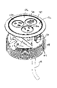
rotatable power center 10 (FIGS. 1-3 and 5-17) is configured for mounting to a
work surface
such as a table, desk, wall, or the like. Power center 10 includes a
stationary outer housing 12, a
rotatable inner housing 14, and at least one electrical or data receptacle 16.
The stationary outer
housing 12 is mountable at an opening formed in a work surface, and defines an
upper opening
18 and also a pair of pivot elements in the form of holes 20 (FIGS. 1, 16, and
17) that are
disposed on opposite sides of the outer housing 12. The rotatable inner
housing 14 is coupled to
the outer housing 12 and is alternately positionable between a use position
(FIGS. 2, 3, and 6-15)
and a non-use position (FIGS. 1 and 5).
100421 Inner housing 14 includes a first inner housing portion 14a having a
first surface 22a that
is located in the upper opening 18 of the outer housing 12 when the inner
housing 14 is in the use
position of FIGS. 2, 3 and 6-15. The inner housing 14 further includes a
second inner housing
portion 14b having a second surface 22b that is located in the upper opening
18 of the outer
housing 12 when the inner housing 14 is in the non-use position of FIGS. 1 and
5. The electrical
or data receptacles 16 are mounted in the rotatable inner housing 14, and in
the illustrated
embodiment, are mounted in respective openings 24 formed or established in
first surface 22a of
first inner housing portion 14a (FIGS. 16 and 17). Each receptacle 16 defines
at least one
receptacle opening 26 (FIG. 13) through which electrical contacts are made
accessible to a plug
(not shown) such as would be associated with an electrical consumer or an
electronic data
device.
100431 As shown in FIGS. 16 and 17, the first inner housing portion 14a has a
pair of mounting
element portions generally in the form of half-cylinders 28a made up of a
plurality of fingers or
projections generally arranged in a half-cylinder shape (shown), or that may
be solid half-
cylinders. Half-cylinders 28a cooperate with another pair of mounting element
portions in the
form of half-cylinders 28b, of the second inner housing portion 14b, to form a
pair of mounting
elements on opposite sides of the inner housing 14 when the first and second
inner housing
portions 14a, 14b are assembled together. A spindle cap 30 is disposed over
adjacent or mated
pairs of the mounting elements 28a, 28b to thereby secure the first and second
pairs of mounting
CA 3052172 2019-08-15
,
,
element portions 28a, 28b together (FIGS. 1-3, 5-7, 9 and 11), which in turn
also secures the first
and second inner housing portions 14a, 14b together. When the spindle caps 30
cover and secure
the respective mounting elements of the inner housing 14, the spindle 30 caps
engage respective
ones of the pivot elements (holes 20) of the outer housing 12, such as shown
in FIGS. 1-3, 5-7, 9
and 11. The rotatable inner housing 14 is thus rotatably supportable by the
outer housing 12 via
engagement of the spindle caps 30 with the holes 20 formed in sidewalls of
outer housing 12.
Optionally, a coil spring or other biasing member may be positioned between
respective inner
surfaces of mounting element portions 28a, 28b and an interior 30a of each
spindle cap 30, to
bias the spindle caps outwardly into engagement with respective holes 20. Such
an arrangement
would also facilitate removal of the inner housing 14 from outer housing 12 by
permitting
spindle caps 30 to be readily depressed inwardly to disengage holes 20.
10044] Each of the first and second inner housing portions 14a, 14b includes a
respective latch
release mechanism 32 (FIGS. 4, 16 and 17) disposed in respective ones of the
first surface 22a
and the second surface 22b. Each latch release mechanism 32 includes a movable
latch member
34 with a thumb-release 34a that is received in one of oblong slots 36, which
are formed in
respective ones of the first and second surfaces 22a, 22b. Distal or base
portions 34b of the latch
members 34 are received in a latch opening 38 (FIGS. 3 and 14) that is defined
between an upper
flange or bezel 40 and a sidewall 42 of the outer housing 12. Latch members 34
are spring-
biased toward the engaging position (shown) by springs 35 arranged along a
latch slider 37
(FIGS. 4, 16 and 17). The latch member 34 associated with whichever surface
22a or 22b is
positioned in upper opening 18 is operable to secure the inner housing 14 in
the use position or
the non-use position by engaging an underside of upper flange 40, such as
shown in FIG. 14.
[0045] Optionally, the receptacles 16 include high voltage AC power
receptacles 16a, such as
110V or 220V receptacles, and low voltage DC power receptacles 16b, such as 5V
to 12V DC
power receptacles including USB-style receptacles 16b (FIGS. 13-15 and 17).
When low
voltage DC power receptacles 16b are provided, the inner housing 14 may
include an electrical
transformer 44 (FIGS. 15-17) that is operable to receive high voltage AC power
from a power
input (e.g. an AC power cord 46, as shown in FIGS. 2 and 3) and that directs
low voltage DC
power to the low voltage DC electrical receptacle 16b.
6
CA 3052172 2019-08-15
, .
[0046] Upper flange 40 of outer housing 12 defines the upper opening 18, and
is configured to
rest atop or along a work surface such as a table or desk, although it is
envisioned that rotatable
power center 10 could also be mounted in substantially any opening formed in a
partition wall, a
solid or raised floor, a ceiling, or the like, without departing from the
spirit and scope of the
present invention. Sidewalls 42 are partial-cylindrical in shape and extend
downwardly from the
upper flange 40. Sidewalls 42 are configured to extend at least partially into
an opening formed
in the work surface. The sidewalls 42 extend down to a threaded generally
cylindrical lower
portion 48 that is configured to receive a threaded collar 50 (FIGS. 1, 16 and
17) for securing the
outer housing 12 to the work surface at the opening formed in the work
surface.
[0047] Referring to FIGS. 1 and 5, second surface 22b of the inner housing's
second portion 14b
is substantially planar and substantially precludes access to the electrical
outlets 16 when the
inner housing is in the non-use position. Optionally, second surface 22b may
be marked with
indicia, or may be partially or substantially made up of a soft surface such
as felt, cork, rubber, or
the like.
[0048] The first inner housing portion 14a and the second inner housing
portion 14b define
respective projection halves 52 that are aligned when the inner housing
portions 14a, 14b are
aligned (FIGS. 2, 3, 10 and 15), and which are configured to receive a
securing collar 54 to
further secure the housing portions 14a, 14b together, in cooperation with
spindle caps 30.
Projection halves 52 are received in a recess region 56 formed in cylindrical
lower portion 48 of
outer housing 12 when inner housing 14 is in the use position, such as shown
in FIGS. 2, 3 and
10. Projection halves 52 may also serve to limit or prevent inner housing from
rotating to a
position that would expose surfaces of the inner housing 14 other than the
first and second
surfaces 22a, 22b, including an area 58 where a power cord 46 exits through an
opening 62 fitted
with a rubber strain relief 64, such as shown in FIGS. 3, 10-12, 14, 16 and
17.
100491 Optionally, and with reference to FIGS. 18-31, another rotatable power
center 110
includes a stationary outer housing 112 and a rotatable or pivotable inner
housing 114 including
a first inner housing portion 114a and a second inner housing portion 14b
(FIGS. 22 and 23).
Various components and surfaces of power center 110 that are substantially
similar or generally
correspond to components and surfaces of power center 10 are given like
numerals by the
addition of 100, such that the components and surfaces of power center 110 may
be understood
7
CA 3052172 2019-08-15
,
with reference to the above discussion, with the following description
addressing only the main
differing features of power center 110. Minor differences include, for
example, the use of a
separate strain relief mount 165 that secures strain relief 164 to second
inner housing portion
114b. Outer housing 112 includes an upper flange or bezel 140 and a generally
cylindrical
threaded lower portion 148 that are substantially the same or identical to the
corresponding
components of power center 10, but with a pair of sidewalls 142 that differ in
the shape and
configuration of pivot elements 120 as compared to pivot elements 20.
100501 Pivot elements 120 are formed as generally circular holes for receiving
respective spindle
caps 130, but each hole has two pairs of slots, including inboard slots 166a
and outboard slots
166b, extending generally upwardly toward upper flange 140 such as shown in
FIGS. 18-21,
24B, 25B, 26B, 29 and 30. As best shown in FIGS. 24B, 25B, 26B, a detent-
engaging element
in the form of a resilient projection 168 is defined between each adjacent
pair of slots 166a,
166b. Projection 168 has a base or proximal region 168a near upper flange 140,
and a distal free
tip portion 168b that is biased inwardly toward and into pivot element or
opening 120, so that tip
portions 168b engage an outer surface 170 of spindle cap 130 when the spindle
cap is inserted
into opening 120.
100511 The spindle cap's outer surface 170 includes or defines three detents
172a-c that are
grooves or depressions oriented longitudinally and evenly spaced
circumferentially apart from
one another around outer surface 170 (FIGS. 20-23). With three detents 172a-c
it will be
appreciated that even spacing yields approximately 120-degree spacing of each
detent from the
adjacent detents. In the illustrated embodiment, the two detent-engaging
projections 168
corresponding to each pivot element opening 120 are aligned so that their tip
portions 168b are
spaced circumferentially apart by approximately 120-degrees along pivot
element opening 120.
This allows the two tip portions 168b to engage respective ones of the three
detents 172a-c when
inner housing 114 is in the use position of FIGS. 18-21, 24A, 24B, and 27-32
(where a first
detent 172a and a second detent 172b are so engaged), and also when the inner
housing 114 is in
the non-use position of FIGS. 26A and 26B (where second detent 172b and a
third detent 172c
are so engaged).
[0052] Accordingly, two tip portions 168b engage two of detents 172a-c to
retain inner housing
114 in either of the use position or the non-use position. The tip portions
168b disengage their
8
CA 3052172 2019-08-15
respective detents 172a-c when sufficient force is applied by a user to first
surface 122a or
second surface 122b (whichever is exposed at upper opening 118) to overcome
the retention
force of tip portions 168b acting on the engaged detents. When sufficient
force is applied, such
as shown in FIGS. 24A-26B, tip portions 168b slide along outer surface 170 of
the spindle cap
130 (FIGS. 25A and 25B) until the next detents 172a-c are engaged (FIGS. 26A
and 26B).
Spindle caps 130 have interiors 130a in which two radial walls 174 extend
inwardly from
opposite directions to engage respective slots 176 defined between adjacent
fingers or
projections 178 of half-cylindrical mounting elements 128a, 128b (FIGS. 22 and
23). This
engagement allows spindle caps 130 to turn with inner housing 114 relative to
outer housing 112
and projections 168.
100531 Although spindle caps 30, 130 are shown as separate elements from inner
housing 114, it
will be appreciated that an inner housing may be used which incorporates
spindles that serve a
similar function of pivotably coupling the inner housing to the outer housing
112, particularly if
the spindles are not also used to secure two inner housing portions together.
For example, such
spindles could be integrally or unitarily formed with an inner housing or
inner housing portion.
It will further be appreciated that, when a detent arrangement is used such as
described above,
detents and detent-engaging elements or surfaces may be formed in any desired
number and in
different locations and/or spacing, including inside of spindle caps or the
like. It is also
envisioned that a single spindle or spindle cap could be used to secure a
pivotable or rotatable
inner housing to an outer housing, without need for a second spindle or
spindle cap on the other
side, provided that the single pivot is structurally designed to handle
increased bending moments
that would be inherent with a single-side mounting arrangement.
100541 Accordingly, the rotatable power and/or data center of the present
invention provides
selective access to electrical and/or data outlets at, along, or near are work
surface and, in the
illustrated embodiments, is adapted for installation at an opening formed or
established in a work
surface, wall, floor, ceiling, or the like. In this way, users of the work
surface can choose
whether to have access to the outlets, or whether to rotate the center so that
only a non-electrical
surface is visible along the work surface. The power center is readily
repositioned by releasing a
latch or catch, or by overcoming a detent feature by the application of
sufficient force in a
desired direction, and rotating the power center to the desired orientation.
9
CA 3052172 2019-08-15
,
,
100551 Changes and modifications in the specifically-described embodiments may
be carried out
without departing from the principles of the present invention, which is
intended to be limited
only by the scope of the appended claims as interpreted according to the
principles of patent law
including the doctrine of equivalents.
CA 3052172 2019-08-15