Language selection

Search

Patent 3052239 Summary

Third-party information liability

Some of the information on this Web page has been provided by external sources. The Government of Canada is not responsible for the accuracy, reliability or currency of the information supplied by external sources. Users wishing to rely upon this information should consult directly with the source of the information. Content provided by external sources is not subject to official languages, privacy and accessibility requirements.

Claims and Abstract availability

Any discrepancies in the text and image of the Claims and Abstract are due to differing posting times. Text of the Claims and Abstract are posted:

  • At the time the application is open to public inspection;
  • At the time of issue of the patent (grant).
(12) Patent: (11) CA 3052239
(54) English Title: MASS SHAPED DETACHING RAZOR DEVICE AND SYSTEM THEREOF
(54) French Title: DISPOSITIF RASOIR DETACHEUR EN FORME DE MASSE ET SYSTEME ASSOCIE
Status: Granted and Issued
Bibliographic Data
(51) International Patent Classification (IPC):
  • B32B 38/18 (2006.01)
  • A21C 3/02 (2006.01)
  • B65G 45/16 (2006.01)
(72) Inventors :
  • CARIDIS, ANDREW ANTHONY (United States of America)
  • GOMEZ ANGULO, MIGUEL ANGEL (Mexico)
  • GONZALEZ GRANADOS, SERGIO (Mexico)
(73) Owners :
  • HEAT AND CONTROL, INC
(71) Applicants :
  • HEAT AND CONTROL, INC (United States of America)
(74) Agent: SMART & BIGGAR LP
(74) Associate agent:
(45) Issued: 2020-06-23
(86) PCT Filing Date: 2017-11-15
(87) Open to Public Inspection: 2018-06-28
Examination requested: 2019-07-31
Availability of licence: N/A
Dedicated to the Public: N/A
(25) Language of filing: English

Patent Cooperation Treaty (PCT): Yes
(86) PCT Filing Number: PCT/IB2017/057134
(87) International Publication Number: WO 2018116024
(85) National Entry: 2019-07-31

(30) Application Priority Data:
Application No. Country/Territory Date
MX/a/2017/007046 (Mexico) 2017-06-05

Abstracts

English Abstract

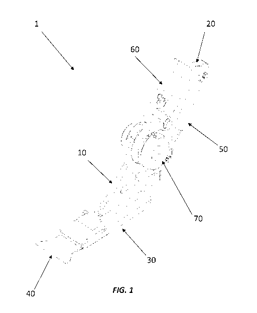
A mass shaped detaching razor device for detaching mass shapes from a laminating roller without damaging the same is provided, said device comprises a main support coupled on its upper section with a lower end of a pressure arm by means of a 5 pivot coupling, the main support is coupled on its lower section with a razor support having on a frontal end a detachment razor, a shock absorber coupled on its lower end to a back end of the main support and coupled by its upper end to an upper end of the pressure arm.


French Abstract

L'invention concerne un dispositif rasoir détacheur en forme de masse destiné à détacher des formes de masse d'un rouleau de stratification sans endommager celui-ci. Ledit dispositif comprend un support principal couplé au niveau de sa section supérieure avec une extrémité inférieure d'un bras de pression au moyen d'un couplage à pivot, le support principal est couplé au niveau de sa section inférieure avec un support de rasoir comportant un rasoir détacheur sur une extrémité avant, un amortisseur couplé au niveau de son extrémité inférieure à une extrémité arrière du support principal et couplé par son extrémité supérieure à une extrémité supérieure du bras de pression.

Claims

Note: Claims are shown in the official language in which they were submitted.


WE CLAIM:
1. Mass shaped detaching razor device comprising
a pressing arm with a lower section and an upper section;
a main support with an upper section, a lower section and
a back section, the upper section of the main support coupled to
the lower section of the pressing arm by means of a first pivot
coupling,
a razor support coupled to the lower section of the main
support;
a detachment razor set on a frontal section of the razor
support;
a shock absorber coupled on its lower section with the back
section of the main support and on its upper section to the upper
section of the pressing arm.
2. The device according to claim 1, wherein the pressing
arms presents.a second pivot coupling above the first pivot
coupling.
3. The device according to claim 2, wherein in said second
pivot coupling a pressure lever is coupled unto, which presents
8

a distal end, a proximal end and two longitudinal sections
perpendicular to each other attached at a vertex, in such a way
that said pressure lever partially wraps the pressing arm.
4. The device according to claim 3, wherein set between the
pressing arm and the pressure lever, a pressure spring is found
in a manner perpendicular to the second pivot coupling.
5. The device according to claim 3, wherein the proximal
end of the pressure lever has a toothed border edge which is
coupled to a plurality of teeth of a brake wheel set on a side
of said first pivot coupling.
6. The device according to claim 1, wherein the razor
support comprises a fixed support as well as a guided support,
wherein the guided support is found in a slidable coupling with
the fixed support by means of a pair of longitudinal flanges set
on the lateral ends of the guided support, which are coupled to
the lateral ends of the fixed support.
7. The device according to claim 6, wherein the guided
support presents a frontal section and a back section, on said
frontal section, the razor is coupled in a detachable manner,
9

underneath said razor a lower support is found, which keeps the
razor coupled unto the guided support.
8. The device according to claim 1, wherein the shock
absorber modifies the inclination of the main support with regard
to the pressing arm, in such a way that when said shock absorber
is found in a retracted position, the main support, presents a
first inclination and when the shock absorber is in an expanded
position, the main support presents a second inclination, the
first inclination being different from the second inclination.
9. A razor detachment system comprising
a right lateral support with an upper end,
a left lateral support with an upper end,
a support bar coupled on the upper ends of said lateral
supports and between the same,
a pivot bar coupled between said lateral supports,
underneath the support bar, and
at least one mass shaped detaching razor device according
to any one of claims 1 through 8 coupled by the first pivot
coupling unto the pivot bar.

10. The razor system according to claim 9, wherein coupled
unto said lateral supports a calibrating hook is found, which
couples the pivot bar by a distal end.
11. The razor system according to claim 10, wherein the
calibrator hook comprises a threaded straight bar which presents
a proximal end as well as a distal end, wherein said distal end
is found in a hooked shape.
12. The razor system according to claim 9, wherein each
lateral support presents at least one guiding groove, over which
the pivot par slides.
13. The razor system according to claim 9, wherein should
the length of the system be excessive, at least one intermediate
support is provided between said lateral supports.
14. The razor system according to claim 9, wherein each
razor of the razor detachment system is found aligned with a
ribbon of a cutter, in such a way so as to ensure that the razor
entirely covers the outline of the shapes of said cutter.
15. The razor detachment system according to claim 14,
wherein each razor is individually calibrated.
11

Description

Note: Descriptions are shown in the official language in which they were submitted.


CA 03052239 2019-07-31
WO 2018/116024 PCT/IB2017/057134
MASS SHAPED DETACHING RAZOR DEVICE AND SYSTEM THEREOF
OBJECT OF THE INVENTION
Present invention provides a mass shaped detaching razor device, which allows
detaching the mass shapes from the laminating roller without damaging the
same, in
such a way that if an imperfection should occur in said device, it would only
be necessary
to remove one specific razor device, not being necessary to stop the
functioning of the
laminating rollers.
BACKGROUND
The concept of a razor device was born from the need of eliminating setbacks
which the use of metallic threads for removing the product from the laminators
entails.
We have knowledge of patent number US 4,966,541 dated October 30, 1990
which describes a wire detachment adjustor for laminating rollers which
present mass in
laminated shapes formed between a pair of roller and separated from a roller
by the
detachment wire subject to tension by means of guides set in order to align
the
detachment wire with end peripheries opposite to the roller, which present an
infinity of
variable positions.
1

CA 03052239 2019-07-31
WO 2018/116024 PCT/IB2017/057134
Similarly, we also have knowledge of patent number US 8,679,563 B1 dated
March 25, 2015 which refers to a laminator which presents a frontal roller
without an
inner groove, a back roller configured to rotate in the opposite direction
from the frontal
roller, a detachment wire partially spiral coupled through the frontal roller
and a
conveyor band connected to a proximal conveyor roller and a distal conveyor
roller.
Metallic threads, although efficient, have the disadvantage of easily becoming
damaged if they are not used in the correct manner, which has as a consequence
the
complete shutdown of the production line in order to make a substitution.
Present device completely replaces the metallic thread, improving the yield of
the
laminating equipment.
BRIEF DECRIPTION OF THE INVENTION
Present invention provides a mass shaped detaching razor device which
comprises a pressing arm with a lower section and an upper section; a main
support with
an upper section, a lower section and a back section, the upper section of the
main
support coupled to the lower section of the pressing arm, by means of a first
pivot
coupling, a razor support coupled to the lower section of the main support; a
detachment razor set on a frontal section of the razor support; a shock
absorber coupled
on its lower section with the back section of the main support and on its
upper section to
the upper section of the pressing arm.
2

CA 03052239 2019-07-31
WO 2018/116024 PCT/IB2017/057134
Additionally, present invention refers to a detachment razor system which
comprises a right lateral support and a left lateral support, a support bar
coupled on the
upper ends of said lateral supports and between the same, a pivot bar coupled
between
said lateral supports, underneath the support bar, and at least one mass
shaped
detaching razor device which comprises a main support, which is found coupled
by its
upper section to a lower end of a pressing arm by means of a pivot coupling,
the main
support is coupled by its lower section to a razor support, the razor support
presents in a
frontal end a detachment razor, a shock absorber coupled by its lower end with
a back
end of the main support and coupled by its upper end to an upper end of the
pressing
arm, said razor device is found coupled unto the pivot bar by the first pivot
coupling.
Brief Description of the Figures
The illustrative embodiment may be described referencing the accompanying
figures, which refer to:
Figure 1 shows a perspective view of a detaching razor device.
Figure 2 shows a lateral view of a detaching razor device.
Figure 3 shows an exploded view of a detaching razor device.
Figure 4 shows a frontal view of a detaching razor system.
Figure 5 shows a lateral view of a detaching razor device mounted on its
support.
3

CA 03052239 2019-07-31
WO 2018/116024 PCT/IB2017/057134
Figure 6 shows a lateral view illustrating the functioning of the detaching
razor
device.
DETAILED DESCRIPTION OF THE INVENTION
The following description makes references to figures 1 through 6 in an
indistinctive manner.
The mass shaped detaching razor device (1) of present invention comprises a
main support (10), which presents a lower section (11), an upper section (12),
a frontal
section (13) and a back section (14), the upper section (12) has a circular
opening (15) in
which a bushing (16) is coupled unto and a securing collar (17), while the
back section
(14) presents at least two perforations (18), which have the same diameter but
are at
different heights; similarly, the lower section (11) is smooth.
Said main support (10) is found coupled by its upper section (12) with a lower
section (21) of a pressing arm (20), it should be noted that said lower
section (21)
presents a circular opening (25), which is coincident with the circular
opening (15) of the
upper section (12) of said main support, likewise said pressing arm (20) also
presents an
upper section (22), a frontal face (23) and at least one lateral face (24);
said coupling
between the main support (10) and the pressing arm (20) corresponds to a first
pivot
coupling, similarly it also presents a second pivot coupling on said at least
one lateral face
(24), said second pivot coupling being set above the first pivot coupling.
4

CA 03052239 2019-07-31
WO 2018/116024 PCT/IB2017/057134
Said main support (10) is found coupled by its lower section (11) unto a razor
support (30), wherein the razor support (30) comprises a fixed support (31) as
well as a
guided support (32), wherein the guided support (32) is found in slidable
coupling with
the fixed support (31) by means of a pair of longitudinal flanges (33), which
are arranged
at the lateral ends of the guided support (32), which are coupled to the
lateral ends of
the fixed support (31).
The guiding support (32) has a frontal section (36) and a back section (37),
on
said frontal section (36) a razor (40) is removably coupled, below said razor
(40) a lower
support (38) is found, which holds the razor (40) coupled unto the guided
support (32). It
should be mentioned that the razor (40) may present shape and size
modifications, which
do not deviate from the scope of the invention.
Set between the back section (14) of the main support (10) and the upper
section (22) of the pressing arm (20) is a gas shock absorber (50), in such a
way that a
lower section (51) of the gas shock absorber (50) is found coupled with the
back section
(14) of the main support (10), and an upper section (52) of the gas shock
absorber (50) is
found coupled with the upper section (22) of the pressing arm (20); the lower
section
(51) of the gas shock absorber (50) is coupled into one of said at least two
perforations
(18) of the back section (14) of the main support (10).
The gas shock absorber (50) modifies the inclination of the main support (10)
.. with regard to the pressing arm (20), in such a way that when said shock
absorber (50) is
found in a retracted position, the main support (10), presents a first
inclination and when
5

CA 03052239 2019-07-31
WO 2018/116024 PCT/IB2017/057134
the gas shock absorber (50) is in an expanded position, the main support (10)
presents a
second inclination, the first inclination being different from the second
inclination.
In said second pivot coupling, a pressure lever (60) is coupled, which
presents a
distal end (61), a proximal end (62) and two longitudinal sections
perpendicular to each
other attached at a vertex, in such a way that said pressure lever (60)
partially wraps the
pressing arm (20), found between the pressing arm (20) and the pressure lever
(60), a
pressure spring (65) is found, which is perpendicular to the second pivot
coupling, so that
it is located on the frontal face (23) of the pressing arm (20); similarly,
the proximal end
(62) of the pressure lever (60) has a toothed border edge (66) which is
coupled to a
plurality of teeth (71) of a brake wheel (70) set on a side of said first
pivot coupling.
The mass shaped razor detachment device (1) of present invention may be
installed together with other similar devices in order to form a detachment
razor system
(100), said detachment razor system (100) presents a right lateral support
(110), a left
lateral support (120), a support bar (130) coupled at the upper ends (111,
121) of said
lateral supports (110, 120) and between them, a pivot bar (140) coupled
between said
lateral supports (110, 120), below the support bar (130), said pivot bar is
coupled unto
the first pivot coupling of said mass-shaped razor detachment devices (1).
On said lateral supports (110, 120) a calibrator hook (150) is found coupled,
said
calibrator hook (150) comprises a threaded straight bar (151) which presents a
proximal
.. end (152) as well as a distal end (153), wherein said distal end (153)
presents in a hooked
shape (154), which couples the pivot bar (140), by means of said calibrating
hook, the
6

CA 03052239 2019-07-31
WO 2018/116024 PCT/IB2017/057134
approaching of the mass shaped detachment razor device (1) to a laminating
roller is
calibrated.
The lateral supports (110, 120) present on their inner surface at least one
guiding groove (112, 122), over which the pivot bar (140) slides.
Should the length of the system (100) be excessive, at least one intermediate
support (160) is provided between said lateral supports, the number of
intermediate
supports (160) shall vary depending on the length of the system (100).
Each razor (40) of the razor detachment system (100) is found aligned with a
ribbon (not shown) of a cutter, in such a way so as to ensure that the razor
(40) entirely
covers the outline of the shapes of said cutter, likewise, each razor (40) is
individually
calibrated.
Alterations to the structure hereby described for the present invention
could be foreseen by those persons skilled in the art. However, it must be
understood
that present description is related with the preferred embodiments of the
invention,
which is merely for illustrative purposes and must not be construed as a
limitation of
present invention. All obvious modifications in the spirit of the invention,
such as changes
to the shape, material and sizes of the different elements which make up the
invention,
must be considered to lie within the scope of the attached claims.
7

Representative Drawing
A single figure which represents the drawing illustrating the invention.
Administrative Status

2024-08-01:As part of the Next Generation Patents (NGP) transition, the Canadian Patents Database (CPD) now contains a more detailed Event History, which replicates the Event Log of our new back-office solution.

Please note that "Inactive:" events refers to events no longer in use in our new back-office solution.

For a clearer understanding of the status of the application/patent presented on this page, the site Disclaimer , as well as the definitions for Patent , Event History , Maintenance Fee  and Payment History  should be consulted.

Event History

Description Date
Common Representative Appointed 2020-11-07
Grant by Issuance 2020-06-23
Inactive: Cover page published 2020-06-22
Inactive: Final fee received 2020-04-24
Pre-grant 2020-04-24
Notice of Allowance is Issued 2020-02-17
Letter Sent 2020-02-17
Notice of Allowance is Issued 2020-02-17
Inactive: Approved for allowance (AFA) 2020-02-13
Inactive: Q2 passed 2020-02-13
Amendment Received - Voluntary Amendment 2019-11-20
Change of Address or Method of Correspondence Request Received 2019-11-20
Common Representative Appointed 2019-10-30
Inactive: S.30(2) Rules - Examiner requisition 2019-09-17
Inactive: Report - No QC 2019-09-16
Inactive: Cover page published 2019-08-29
Inactive: First IPC assigned 2019-08-22
Inactive: IPC assigned 2019-08-22
Inactive: IPC assigned 2019-08-21
Inactive: Acknowledgment of national entry - RFE 2019-08-20
Correct Applicant Requirements Determined Compliant 2019-08-20
Inactive: IPC assigned 2019-08-20
Application Received - PCT 2019-08-20
Inactive: First IPC assigned 2019-08-20
Inactive: Office letter 2019-08-20
Letter Sent 2019-08-20
Advanced Examination Requested - PPH 2019-08-01
Advanced Examination Determined Compliant - PPH 2019-08-01
Early Laid Open Requested 2019-08-01
National Entry Requirements Determined Compliant 2019-07-31
Request for Examination Requirements Determined Compliant 2019-07-31
All Requirements for Examination Determined Compliant 2019-07-31
Application Published (Open to Public Inspection) 2018-06-28

Abandonment History

There is no abandonment history.

Maintenance Fee

The last payment was received on 2019-07-31

Note : If the full payment has not been received on or before the date indicated, a further fee may be required which may be one of the following

  • the reinstatement fee;
  • the late payment fee; or
  • additional fee to reverse deemed expiry.

Patent fees are adjusted on the 1st of January every year. The amounts above are the current amounts if received by December 31 of the current year.
Please refer to the CIPO Patent Fees web page to see all current fee amounts.

Fee History

Fee Type Anniversary Year Due Date Paid Date
Registration of a document 2019-07-31
MF (application, 2nd anniv.) - standard 02 2019-11-15 2019-07-31
Request for examination - standard 2019-07-31
Basic national fee - standard 2019-07-31
Final fee - standard 2020-06-17 2020-04-24
MF (patent, 3rd anniv.) - standard 2020-11-16 2020-11-06
MF (patent, 4th anniv.) - standard 2021-11-15 2021-11-05
MF (patent, 5th anniv.) - standard 2022-11-15 2022-11-11
MF (patent, 6th anniv.) - standard 2023-11-15 2023-11-10
Owners on Record

Note: Records showing the ownership history in alphabetical order.

Current Owners on Record
HEAT AND CONTROL, INC
Past Owners on Record
ANDREW ANTHONY CARIDIS
MIGUEL ANGEL GOMEZ ANGULO
SERGIO GONZALEZ GRANADOS
Past Owners that do not appear in the "Owners on Record" listing will appear in other documentation within the application.
Documents

To view selected files, please enter reCAPTCHA code :


To view images, click a link in the Document Description column. To download the documents, select one or more checkboxes in the first column and then click the "Download Selected in PDF format (Zip Archive)" or the "Download Selected as Single PDF" button.

List of published and non-published patent-specific documents on the CPD .

If you have any difficulty accessing content, you can call the Client Service Centre at 1-866-997-1936 or send them an e-mail at CIPO Client Service Centre.


Document
Description 
Date
(yyyy-mm-dd) 
Number of pages   Size of Image (KB) 
Claims 2019-11-19 4 95
Description 2019-07-30 7 199
Abstract 2019-07-30 2 71
Drawings 2019-07-30 6 146
Claims 2019-07-30 4 80
Representative drawing 2019-07-30 1 15
Representative drawing 2020-05-27 1 7
Courtesy - Certificate of registration (related document(s)) 2019-08-19 1 107
Notice of National Entry 2019-08-19 1 202
Commissioner's Notice - Application Found Allowable 2020-02-16 1 503
Prosecution/Amendment 2019-07-30 2 174
National entry request 2019-07-30 11 316
Declaration 2019-07-30 5 259
International search report 2019-07-30 2 71
Courtesy - Office Letter 2019-08-19 1 57
Examiner Requisition 2019-09-16 3 157
Amendment 2019-11-19 8 188
Final fee 2020-04-23 4 123