Note: Descriptions are shown in the official language in which they were submitted.
CA 03052346 2019-08-01
1
Adhesive Mat and Use of an Adhesive Mat for Determining a Distribution of
Agricultural Scattering Material by Imaging
The invention relates to an adhesive mat for determining the distribution of
agricultural scattering
material, as well as the use of an adhesive mat for determining a distribution
of agricultural
spreading material by imaging.
Generic methods and adhesive mats for determining the distribution of
fertilizer grains, in
particular transverse to the direction of travel of a fertilizer spreader, are
known, for example, from
DE 10 2014 103 964 Al. According thereto, adhesive mats or boards are first
laid out to collect
and retain spread fertilizer grains. The fertilizer grains are then spread
with a fertilizer 'spreader
travelling over a ground region covered with adhesive mats or boards. The
bestrewed adhesive
mats are then imaged in at least one digital camera image. Finally, the
fertilizer grains are
localized in the camera image and an actual distribution of the fertilizer
grains on the adhesive
mats is calculated. This actual distribution can then be compared to a desired
distribution and the
result can be used to adjust the distribution members.
It has been found that handling such adhesive mats can be impractical,
especially when working
on arable land. For example, it is difficult for one person to transport
several adhesive mats at the
same time, so that a large number of trips is necessary between the
agricultural vehicle in which
the adhesive mats are stored and the places where the adhesive mats are to be
laid out. In
addition, carrying, laying out and picking up the adhesive mats can be
impractical.
The object of the invention is therefore to provide adhesive mats which are
easy to handle, in
particular when used on arable land.
The object set is satisfied with an adhesive mat according to claim 1. Further
advantageous
embodiments of the invention are disclosed in the dependent claims.
An adhesive mat is herein to be understood as being a planar element which is
made, in particular,
of a flexible material. For example, it can be made of plastic material. The
plastic material can be,
in particular, a thermoplastic elastomer. The adhesive mat can extend
substantially in one plane,
where the extension in this plane (length, width) is many times greater than
in a direction
perpendicular to this plane (thickness). The adhesive mat can basically have
any geometric
shape; it is preferably formed to be cuboid.
According to the invention, the adhesive mat comprises a collecting region
which is at least in
part bordered at least on one side by an edge region. According to one
alternative, the edge
region is provided with a passage opening. This allows, in particular, easy
transport of several
CA 03052346 2019-08-01
2
adhesive mats which are connected to each other, for example, by way of their
respective
openings, and can thusly be carried together. Furthermore, there is the
advantage that several
adhesive mats can be suspended simultaneously for storage from a suitable
holder, such as a
hook. Alternatively or additionally, the edge region of the adhesive mat can
also comprise a
handle, where the handle enables gripping the adhesive mat with one hand. In a
particularly
advantageous embodiment of the invention, the passage opening itself can be
formed such that
it can be used as a handle. The handle can also be formed by an element which,
for example, is
formed to be loop-shaped perpendicular to the plane in which the adhesive mat
extends
substantially.
The adhesive mat can preferably be formed in one piece, i.e., the edge region
of the adhesive
mat confines the collecting region of the adhesive mat on at least one side
solely by its formation.
This can be achieved in that the edge region is structured to be raised or
lowered relative to the
collecting region, i.e. the edge region has a thickness that differs from the
collecting region, or in
that its surface or material nature (for example, density or material) is
different from that of the
collecting region. In particular, the edge region can completely confine the
collecting region on all
sides and thus form a "frame" around the collecting region.
The collecting region can comprise a plurality of knob-like elevations which
are arranged in a grid
in the collecting region. This provides the advantage that a large number of
collecting spaces, in
particular of equal size, are formed by the elevations, in which the grains of
the spreading material
can be retained at the points where they impinge on the adhesive mat. The knob-
like elevations
can have the shape, for example, of rods, tongues, hooks or the like extending
from the surface
of the mat.
The collecting region can further comprise at least one marking. Such a
marking can be helpful
in many ways in preparation for the recording of the adhesive mat with a
camera. It can facilitate
positioning of a digital camera, e.g. the camera of a smartphone, when
recording the grain
distribution, or enable, by a particular coloration, color calibration of the
camera or an application
used for the evaluation of a camera image. In particular, the marking can have
a known coloration
that differs from the base color of the adhesive mat. The base color of the
adhesive mat can be
the color that is predominantly exhibited by the adhesive mat, in particular
the collecting region.
The at least one marking can alternatively or additionally be formed by a
recessed area in the grid
of the knob-like elevations. For example, the marking can already be formed
during the production
process of the adhesive mat, which can ensure that the marking is uniform for
all adhesive mats.
The collecting region of the adhesive mat can be formed to be rectangular in
the plane in which
the adhesive mat extends substantially, where a marking is applied in each
corner of the adhesive
CA 03052346 2019-08-01
3
mat. This is advantageous because the markings thereby allow the user to
easily position the
camera such that the collecting region optimally fills the digital camera
image to be captured, i.e.,
that the entire collecting region and at the same time as little as possible
of the edge region is
recorded.
The passage opening can be formed to have an extension along one axis that is
located in the
plane in which the adhesive mat extends substantially of less than 350 mm and
more than 90
mm, in particular less than 175 mm and more than 110 mm, and to have an
extension along a
second axis located in this plane of the adhesive mat, which is perpendicular
to the first axis of
less than 100 mm and more than 35 mm, in particular less than 60 mm and more
than 40 mm.
This configuration of the passage opening makes it possible to easily pick up,
carry and lay out
an adhesive mat with one hand.
The invention also provides the use of at least one adhesive mat described
above for determining
a distribution of agricultural spreading material by imaging according to
claim 7.
The at least one adhesive mat can be arranged at a location on a field or a
test area. Granular
spreading material can subsequently be distributed over the adhesive mat from
a spreader vehicle
passing by the adhesive mat, which can be, in particular, a centrifugal
spreader. Finally, the
distribution of the spreading material on the adhesive mat can be determined
by way of an
imaging method. The actual distribution obtained in this way can then be
compared to a desired
distribution stored in a memory or otherwise provided, and the result of the
comparison can be
used for adjusting the distribution members of the distribution vehicle.
The passage opening can be used in the process as a handle for laying out or
carrying the
adhesive mat.
During the imaging process, the markings on the mat can be used to correctly
position the
camera.
The adhesive mat can have one or more of the features described above.
Further features of the present invention shall be illustrated below using the
exemplary figures,
where
Fig. 1 shows a schematic representation of the use according to the
inventive of an
adhesive mat; and
Fig. 2 shows a schematic representation of an adhesive mat according to
the invention.
CA 03052346 2019-08-01
4
Figure 1 schematically shows the use of an adhesive mat 1 for determining the
distribution of
agricultural spreading material by imaging on an area 3. At least one, but
typically two or more,
adhesive mats 1 are laid out on arable land, a field, a test area or the like.
Subsequent thereto,
an agricultural spreader vehicle 4, for example a centrifugal spreader, moves
past the adhesive
mats 1 and distributes the granular spreading material 2 over the area 3.
Adhesive mats 1
described in more detail below are formed such that they retain granular
spreading material 2
distributed in the region of adhesive mats 1 substantially at the locations
where they impinge
adhesive mats 1.
Once a portion of granular spreading material 2 has been distributed in this
manner onto adhesive
mats 1, an image 7 of the distribution of spreading material 2 on adhesive
mats 1 is created by
way of an image recording device 5, which can be, for example, a digital
camera, in particular an
integrated camera of a mobile radio device 6 (e.g. a smartphone). In
particular, a separate image
can be created for each adhesive mat 1 in the process.
Image 7 can then be evaluated in digital form by a processing unit 8 in order
to determine an
actual distribution of granular spreading material 2 on adhesive mat 1.
According to one example,
processing unit 8 as well as camera 5 are part of mobile radio device 6, so
that the recording and
evaluation can be performed with the same device. This eliminates the need to
transfer images 7
to another device, which saves time and resources.
Alternatively, however, processing unit 8 can also be part of on-board
computer 4a of spreader
vehicle 4, or of a separate computer system 9. In this case, the transmission
of images 7 takes
place preferably by way of wireless communication between mobile radio device
6 and on-board
computer 4a or computer system 9, respectively. Images 7 can also be
transmitted by way of a
cable, e.g. a USB cable, from mobile radio device 6 or directly from image
recording device 5 to
on-board computer 4 a or computer system 9.
Another option is to digitize a copy of image 7 by way of a scanner and to
then transfer it to on-
board computer 4a or computer system 9.
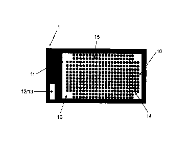
Figure 2 schematically shows an adhesive mat 1 according to the invention.
Adhesive mat 1 there
comprises a collecting region 10 which is completely confined by an edge
region 11. Adhesive
mat 1 is there typically formed as one piece, and collecting region 10 is
lowered relative to edge
region 11. In other words, collecting region 10 forms a recess in adhesive mat
1, which is confined
by edge region 11. The adhesive mat can also be designed differently, for
example, the edge
region and the collecting region could be formed by way of multi-component
injection molding. In
particular, the edge region can be made of polypropylene (PP) or polyethylene
(PE) and the
collecting region made of thermoplastic elastomer. External dimensions of the
adhesive mat can
CA 03052346 2019-08-01
be in the range of 550 mm to 700 mm for the length and in the range of 350 mm
to 450 mm for
the width. The thickness of edge region 11 can be in the range of 10 mm to 15
mm. The
dimensions of collecting region 10 can be in the range of 500 mm to 650 mm for
the length and
in the range of 300 mm to 400 mm for the width. The thickness of the adhesive
mat in collecting
region 10 can be in the range of 3 mm to 6 mm.
In the embodiment shown in Figure 2, edge region 11 has a passage opening 12
which here at
the same time can be used as a handle. The dimensions of the passage opening
12 are chosen
such that they allow adhesive mat 1 to be picked up and carried with one hand.
The length of the
passage opening can be in the range of 90 mm to 350 mm, preferably in the
range of 110 mm to
175 mm, the width in the range of 35 mm to 100 mm, preferably in the range of
40 mm to 60 mm.
Furthermore, such a configuration of passage opening 12 allows several
adhesive mats 1 to be
carried simultaneously with one hand. In this process, a user arranges
adhesive mats 1 such that
passage openings 12 come to lie one above the other, and then reaches through
the resulting
opening of all adhesive mats 1 at the same time with one hand.
Similarly, passage openings 12 can also be used to store a plurality of
adhesive mats 1 in a
space-saving manner, e.g. on a hook or a pole.
The collecting region of adhesive mat 1 contains knob-like elevations 14 which
are arranged in
a grid. Through elevations 14, a plurality of collecting spaces 15 are formed,
in which granular
spreading material 2 collects when using adhesive mat 1. The spacings of the
grid are typically
dimensioned such that the size of the collecting spaces 15 respectively
corresponds
approximately to the size of granular spreading material 2.
The clear widths of collecting spaces 15 can preferably be in the range of 2
to 5 mm. Thereby,
granular spreading material 2, e.g. the grains of conventional types of
fertilizer having grain sizes
of, for example, 1 mm to 3 mm, can be collected in collecting spaces 15
individually and/or in
suitably small groups of, for example, at most five grains of spreading
material 2. Depending on
the profile of elevations 14 protruding between collecting spaces 15, this
results in advantageous
grid spacings, i.e. spacings between the centers of elevations 14, of about 5
mm to 10 mm.
Knob-like elevations 14 can have a plurality of different profiles which
promote the retention of
granular spreading material 2. For example, elevations 14 can be in the shape
of sticks or
tongues, i.e. shapes that arise essentially by the extrusion of a circle or an
ellipse, such as
cylinders or cones with a circular or elliptical base. The height of
elevations 14 can be in the range
of 8 mm to 12 mm.
CA 03052346 2019-08-01
= 6
Adhesive mat 1 can be made of a material which is durable, easy to handle and
flexible. In
particular, the mat can be made of plastic material, for example, a
thermoplastic elastomer. By
choosing a suitable Shore A hardness and thickness of the mat, it can be
ensured that the mat is
easy to carry and stable, and can be well laid out even on uneven ground. For
example, the Shore
A hardness can be in the range of 60 to 90.
Figure 2 also shows that collecting region 10 of adhesive mat 1 comprises
markings 16. Markings
16 are formed in this embodiment by recesses in the grid of elevations 14 and
arranged in the
corners of collecting region 10. In particular such an arrangement makes it
easier for the user in
the use of adhesive mat 1 according to invention to position image recording
device 5 such that
collecting region 10 optimally fills captured image 7. Namely, camera 5 can
then be positioned
such that markings 16 appear exactly at the edge of the image in the
viewfinder or on the screen
of camera 5. That way, it can be ensured that, on the one hand, the entire
collecting region 10 is
imaged and, on the other hand, that the smallest possible part of edge region
11 or other parts of
adhesive mat 1 appears on image 7. This facilitates the evaluation of image 7
by processing unit
8, since parts of adhesive mat 1 not relevant for the evaluation do not appear
on image 7 to the
extent possible, and image recognition is thus simplified.
The size of markings 16 is selected such that they are easy to recognize for
the user when
recording. The shapes and sizes for such markings can be, for example, squares
having a side
length of 30 mm to 40 mm.
Markings 16 can also be shaped and/or arranged differently. It is also
conceivable that an
application is executed on a mobile radio device 6 which recognizes a marking
already during the
preparation of the recording and suggests to the user to position camera 5 of
mobile radio device
6 in a certain manner, for example, by appropriate instructions which are
displayed to the user on
the screen of camera 5. The application could know from a database the shape
of adhesive mat
1 or marking 16 used and therefore also suggest the optimal position of camera
5 solely based
on a marking 16. For example, the application could extract from the database
that marking 16
for a given adhesive mat has the shape of an arrow which runs parallel to an
edge of the collecting
region. In addition, the application could have the information that marking
16 is arranged at a
certain point of the collecting region, for example, in the center of the
collecting region or at one
of the four edges, where the edges "top", "bottom", "right" and "left "are
defined by the direction
of the arrow. The application could then query the user for the information of
how the arrow is
oriented, based on the arrangement of the adhesive mat in the field, relative
to the direction of
travel of spreader vehicle 4. Based on this, the application could then give
the user instructions
on how to position camera 5 so that e.g. the upper edge of a recorded image 7
always shows that
CA 03052346 2019-08-01
7
edge of collecting region 10 which in the direction of travel is farther away.
This would ensure that
all recorded images 7 have the same orientation.
Markings 16 can further have a coloration that differs from the color of
interior space 10 of
adhesive mat 1. In particular, one or more of the markings can have a known
coloration that can
be used by processing unit 8 to color-calibrate image 7. This is advantageous
for the reason that
the use of adhesive mat 1 can take place under different ambient conditions,
in particular at
different light conditions. An image 7 taken on arable land in the open air
can differ in hue from
an image taken using an adhesive mat 1 in a test area on a factory floor,
although the same
adhesive mat 1 and the same spreading material were used.
It is understood that the features mentioned in the embodiments described
above are not
restricted to these specific combinations and are also possible in any other
combination. In
particular, the adhesive mat or its passage opening can have different shapes
or geometries.