Note: Descriptions are shown in the official language in which they were submitted.
CA 03053284 2019-08-09
WO 2018/148694
PCT/US2018/017886
PUMP GUARD AND METHODS OF USE THEREOF
CROSS-REFERENCE TO RELATED APPLICATIONS
To the full extent permitted by law, the present United States Non-provisional
Patent
Application hereby claims priority to and the full benefit of United States
Provisional
Application entitled "PUMP SEAL LIFE IMPROVEMENT AND FIRE PROTECTION
APPARATUS AND SYSTEM AND METHODS OF USE THEREOF," having assigned
serial number 62/458,188, filed on February 13, 2017, incorporated herein by
reference in its
entirety.
TECHNICAL FIELD
This disclosure relates to a pump guard and methods of use thereof More
specifically
the disclosure relates to a fire protection shield for a mechanical seal
assembly and coupler
between a drive motor and fluid pump.
BACKGROUND
Fluid pumps are utilized in a variety of industries to move fluids and to
pressurize
fluids. Some pump system require pump protection systems, for example, when
involving the
operation of pumps handling flammable fluids, such as a pump for an organic
flammable
liquid with mechanical seals. These pumps are generally operating at elevated
temperatures,
where leakages of fluid around the pump mechanical seal area, which is common,
may
provide a source of fire. Seal degradation and failure is accelerated by high
temperatures,
which organic fluids are commonly operated at, leading to a seal failure,
which in turn may
lead to a source of fire or an actual fire. This fire once started at the pump
may spread to
other parts of the plant, and is one of the most common fire hazards
associated with this type
of pump operation.
One disadvantage is that the manufactures of the individual components of a
fluid
pump system, such as the mechanical seal assembly, coupler, motor and fluid
pump are often
manufactured separately and therefore the above fire protection issues have
generally not
been addressed by the component manufacture. Make shift solutions have been
used
generally by either pump skid integrators or more common by users/operators
themselves.
One approach includes attempts to improve cooling of mechanical seals in order
to
increase their longevity have generally included modifying or replacing
coupling guards to
direct motor air to flow over the pump seal thereby cooling it. Coupling
guards are generally
1
CA 03053284 2019-08-09
WO 2018/148694
PCT/US2018/017886
a metal shield whose function is to protect users from accessing the rotating
coupling and
shaft connecting motor and pump. While these modifications to the coupling
guard may have
provided the desired cooling effect, one disadvantage to this approach is
abundant air flow to
fan a fire, and should the seal begin to leak, thereby promoting the fire, and
aiding in its
spread.
Another approach to mitigate pump fires has been to place heat, smoke, and
fire
sensing equipment and water sprays or fire suppressing foam spray delivery
systems
proximate the pump seal area which automatically discharge in the event of a
sensed fire.
Some systems have been observed by which the foam spray nozzles have been
directly
inserted into the coupling guard housings which may be more effective than the
more
generalized nozzle placement. These fire mitigation systems have been limited
in
effectiveness as the area to be covered for fire protection is not limited,
and these nozzles
alone positioned proximate the mechanical seal do not provide a system to
contain the spread
of fire. These fire suppression systems have addressed the fire once it breaks
out, none have
addressed the cooling and longevity of the seals themselves to help prevent
leakage.
Moreover, none of the above systems as described have been observed to be
commercially available. Further, none have addressed the simultaneous needs to
address air
cooling needed to extend seal life and to protect mechanical seals from pre-
mature failure,
due to heating, while additionally mitigating its effect to fan the fire, and
once failed to
prevent fluid spread, a fire from igniting the discharging flammable liquid,
suppress any fire
which may have started and the spread of fire beyond the mechanical seal.
Therefore, it is readily apparent that there is a need for a pump guard and
methods of
use thereof that functions to enable a combination of features including
address the
simultaneous needs to address air cooling to extend seal life and to protect
mechanical seals
from pre-mature failure, due to heating, while additionally mitigating the
cooling air flow
effect to fan the fire, and once failed to prevent fluid spread, a fire from
igniting the
discharging flammable liquid, and suppress any fire which may have started and
the spread of
fire beyond the mechanical seal.
2
CA 03053284 2019-08-09
WO 2018/148694
PCT/US2018/017886
BRIEF SUMMARY
Briefly described, in an example embodiment, the present disclosure overcomes
the
above-mentioned disadvantages and meets the recognized need for a pump guard
and
methods of use thereof, that generally includes an inner housing or guard
configured to the
cover mechanical seal assembly and the motor coupling housed between a drive
motor and a
fluid and an outer "Air scoop" housing or guard configured to direct motor
induced airflow
over the mechanical seal assembly.
According to its major aspects and broadly stated, the present disclosure in
its
exemplary form is a pump guard and methods of use thereof, that generally
includes an inner
housing or guard configured to the cover mechanical seal assembly and the
motor coupling
housed between a drive motor and a fluid pump to enable foam spray nozzles to
be directly
inserted into the coupling guard housings for fire suppression and an outer
"Air scoop"
housing or guard configured to direct motor induced airflow over the
mechanical seal
assembly thereby cooling it to extend seal life and to protect mechanical
seals from pre-
mature failure.
In an exemplary embodiment, the pump guard and methods of use may include a
shroud for a motor, motor-pump coupler, pump mechanical seal assembly, and
pump, the fire
containment and cooling including an outer housing configured as an air scoop
for a first
zone to direct cooling air from the motor over the pump mechanical seal
assembly, the outer
housing formed of a first outer housing side wall and a second outer housing
side wall, and a
first arching top connected thereto the first outer housing side wall and the
second outer
housing side wall, and an inner housing positioned within the outer housing
and configured to
seal a second zone thearound the motor, motor-pump coupler, and pump
mechanical seal
assembly, the inner housing formed of a platform, extending therefrom a first
inner housing
side wall and a second inner housing side wall, and a second arching top
connected thereto
the first inner housing side wall and the second inner housing side wall, and
one or more end
equipment seals connected thereto the platform, the first inner housing side
wall and the
second inner housing side wall, and the second arching top.
In another exemplary embodiment, the pump guard and methods of use may include
a
fire containment and cooling system, the system includes a motor, a motor-pump
coupler, a
pump mechanical seal assembly, a pump, an outer housing configured as an air
scoop for a
3
CA 03053284 2019-08-09
WO 2018/148694
PCT/US2018/017886
first zone to direct cooling air from the motor over the pump mechanical seal
assembly, the
outer housing formed of a first outer housing side wall and a second outer
housing side wall,
and a first arching top connected thereto the first outer housing side wall
and the second outer
housing side wall, and an inner housing positioned within the outer housing
and configured to
seal a second zone around the motor, the motor-pump coupler, and the pump
mechanical seal
assembly, the inner housing formed of a platform, extending therefrom a first
inner housing
side wall and a second inner housing side wall, and a second arching top
connected thereto
the first inner housing side wall and the second inner housing side wall, and
one or more end
equipment seals connected thereto the platform, the first inner housing side
wall and the
second inner housing side wall, and the second arching top.
In still a further exemplary embodiment of the pump guard and methods of use,
a
method of fire containment and cooling, the method includes providing a shroud
having a
motor, a motor-pump coupler, a pump mechanical seal assembly, a pump, an outer
housing
configured as an air scoop for a first zone to direct cooling air from the
motor over the pump
mechanical seal assembly, the outer housing formed of a first outer housing
side wall and a
second outer housing side wall, and a first arching top connected thereto the
first outer
housing side wall and the second outer housing side wall, and an inner housing
positioned
within the outer housing and configured to seal a second zone thearound the
motor, the
motor-pump coupler, and the pump mechanical seal assembly, the inner housing
formed of a
platform, extending therefrom a first inner housing side wall and a second
inner housing side
wall, and a second arching top connected thereto the first inner housing side
wall and the
second inner housing side wall, and one or more end equipment seals connected
thereto the
platform, the first inner housing side wall and the second inner housing side
wall, and the
second arching top, providing an inner housing aperture configured with a fire
sensing device
therein the second zone, and monitoring the second zone for a fire.
A feature of the pump guard and methods of use is the ability to provide a
combination shield or guard such as an inner housing, as well as an outer air
scoop housing.
Another feature of the pump guard and methods of use is the ability to provide
an
inner housing to cover the rotating units of the pump-motor coupling and the
pump
mechanical seal assembly, such that it is isolated from air flows, and durable
enough to
contain a fire that may emanate from the pump seal or mechanical seal
assembly.
4
CA 03053284 2019-08-09
WO 2018/148694
PCT/US2018/017886
Yet another feature of the pump guard and methods of use is the ability to
contain or
position therein the inner housing, cover, or guard any fire suppression
nozzles, should they
be used.
Yet another feature of the pump guard and methods of use is the ability to
configure
the inner housing, cover, or guard of a flame and heat resistant material such
that it could
limit a fire's spread.
Yet another feature of the pump guard and methods of use is the ability to
position
therein the inner housing, cover, or guard fire suppression nozzles and fire
sensing lines or
other apparatus to extinguish a fire.
Yet another feature of the pump guard and methods of use is the ability to
provide fire
suppressant via the nozzles, such as water or foam based or may use other fire
suppressing
fluids or substances.
Yet another feature of the pump guard and methods of use is the ability to
contain
foam or other extinguishing agent in the inner housing.
Yet another feature of the pump guard and methods of use is the ability to
provide
catch or drip trays, liners or edging constructed to collect drips from leaks
of pump
mechanical seal and/or foam fire agents to limit spread of fires.
Yet another feature of the pump guard and methods of use is the ability to
provide a
confined inner space in which any fire may be contained, should it be
initiated by a
mechanical seal leak.
Yet another feature of the pump guard and methods of use is the ability to
provide a
confined inner space in which air flow may be restricted, should a fire be
initiated by a
mechanical seal leak.
Yet another feature of the pump guard and methods of use is the ability to
provide an
outer air scoop housing, cover, or guard configured to surround the inner
housing.
5
CA 03053284 2019-08-09
WO 2018/148694
PCT/US2018/017886
Yet another feature of the pump guard and methods of use is the ability to
provide an
outer air scoop housing, cover, or guard configured to capture cooling air
from the motor fan,
or any other fan, and to direct the airflow over the inner housing toward the
pump seal or
mechanical seal assembly to provide the desired cooling effect for the pump
seal or
mechanical seal assembly.
Yet another feature of the pump guard and methods of use is the ability to
provide an
outer air scoop housing, cover, or guard configured to provide airflow cooling
for
.. instrumentation used to monitor the pump seal conditions, such as vibration
sensors or other
instrumentation which may be placed on or near pump seals or mechanical seal
assembly and
exposed to high temperatures around the pump seal area. These instruments may
be for
preventive purposes to monitor pump and/or seal conditions before the pump
and/or seal
progress to an unstable state.
Yet another feature of the pump guard and methods of use is the ability to
provide an
inner and outer housing, cover, or guard configured to isolate the cooling air
flow from the
pump seal area so as not to feed air to or fanning a fire, while still
providing protective
functions of an inner housing that limit access to rotating components and
prevent spread of
any fires from the pump mechanical seal area where a leak or fire may occur.
Yet another feature of the pump guard and methods of use is the ability to
provide
inner and outer housing, cover, or guard configured to fit, placed over, or
positioned on any
conventional pump-motor arrangement and fitted to new or existing pump-motor
systems.
These and other features of the pump guard and methods of use will become more
apparent to one skilled in the art from the prior Summary and following Brief
Description of
the Drawings, Detailed Description of exemplary embodiments thereof, and
Claims when
read in light of the accompanying Drawings or Figures.
BRIEF DESCRIPTION OF THE DRAWINGS
The present pump guard and methods of use will be better understood by reading
the
Detailed Description of the Preferred and Selected Alternate Embodiments with
reference to
6
CA 03053284 2019-08-09
WO 2018/148694
PCT/US2018/017886
the accompanying drawing Figures, in which like reference numerals denote
similar structure
and refer to like elements throughout, and in which:
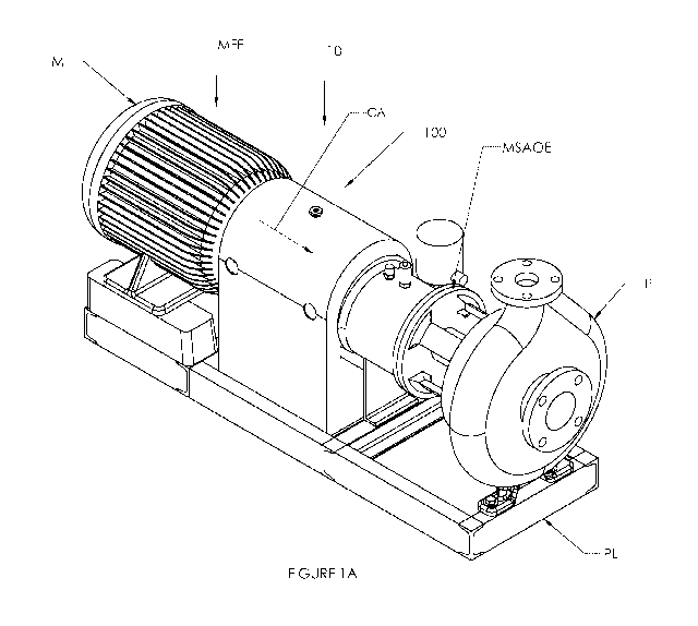
FIG. 1A is a perspective view of an exemplary embodiment of the pump guard
fitted
to a motor-pump assembly;
FIG. 1B is a perspective view of an exemplary embodiment of the pump guard
fitted
to a motor-pump assembly, shown with the outer housing hinged open;
FIG. 1C is a cross-sectional view of an exemplary embodiment of the pump guard
and methods of use fitted to a motor-pump assembly, showing the motor coupler
and pump
mechanical seal assembly;
FIG. 2A is a perspective view of an exemplary embodiment of the inner housing
of
the pump guard and methods of use, according to FIG. 1;
FIG. 2B is a side view of an exemplary embodiment of the inner housing of the
pump
guard and methods of use, according to FIG. 1;
FIG. 2C is an end view of an exemplary embodiment of the inner housing of the
pump guard and methods of use, according to FIG. 1;
FIG. 2D is a perspective view of an exemplary embodiment of the inner housing
of
the pump guard and methods of use, according to FIG. 1 with removeable
equipment seal;
FIG. 2E is a perspective view of an alternate exemplary embodiment of the
inner
housing of the pump guard and methods of use;
FIG. 3A is a perspective view of an exemplary embodiment of the outer housing
of
the pump guard and methods of use, according to FIG. 1;
FIG. 3B is a first side view of an exemplary embodiment of the outer housing
of the
pump guard and methods of use, according to FIG. 1;
7
CA 03053284 2019-08-09
WO 2018/148694
PCT/US2018/017886
FIG. 3C is an end view of an exemplary embodiment of the outer housing of the
pump guard and methods of use, according to FIG. 1;
FIG. 3D is a second side view of an exemplary embodiment of the outer housing
of
the pump guard and methods of use, according to FIG. 1; and
FIG. 4 is a flow diagram of a method of filtering a portion of suspended
substances and/or
dissolved substances from an effluent.
DETAILED DESCRIPTION
In describing the exemplary embodiments of the present disclosure, as
illustrated in
FIGS. 1A, 1B, 1C, 2A, 2B, 2C, 2D, 2E, 3A, 3B, 3C, 3D, and 4 specific
terminology is
employed for the sake of clarity. The present disclosure, however, is not
intended to be
limited to the specific terminology so selected, and it is to be understood
that each specific
element includes all technical equivalents that operate in a similar manner to
accomplish
similar functions. Embodiments of the claims may, however, be embodied in many
different
forms and should not be construed to be limited to the embodiments set forth
herein. The
examples set forth herein are non-limiting examples, and are merely examples
among other
possible examples.
Referring now to FIGS. 1A, 1B, and 1C, by way of example, and not limitation,
there
is illustrated an example embodiment combination housing, cover, shroud, or
guard device,
such as pump guard 10. Pump guard 10 may be configured of two or more housing,
cover,
guard, shroud, or isolation zone, such as outer housing, encase, cover, guard,
or isolation
zone (outer housing) 100 and inner housing, cover, guard, shroud, or isolation
zone (inner
housing) 200. Both outer housing 100 and inner housing 200 may be positioned
to
substantially cover, encase, and/or seal pump rotating parts and shaft seal
area, such as
motor-pump coupler C and pump mechanical seal assembly MSA positioned and
mechanically connected therebetween motor M and fluid pump P, and all
positioned or
resting thereon platform PL. A mechanical seal is an apparatus utilized to
contain fluid,
within a vessel, such as pumps (especially pumps handling flammable fluids),
mixers, or the
like where a rotating shaft passes through a stationary housing. A coupler is
a mechanical
apparatus utilized to connect two rotating shafts together.
8
CA 03053284 2019-08-09
WO 2018/148694
PCT/US2018/017886
Referring again to FIG. 1A, 1B, and 1C which shows a perspective view of pump
guard 10 configured with outer housing 100 in a closed or sealed position to
cover, shroud,
seal therearound, or isolate an area, such as first zone Z1 between
approximately motor front
edge MFE and extend to mechanical seal assembly outer edge MSAOE and down to
.. platform PL. It is contemplated herein that outer housing 100 may extend
thereto pump front
edge PFE. Preferably, outer housing 100 and first zone Z1 are configured to
capture cooling
air CA from the motor fan, or any other fan, and to direct the airflow of
cooling air CA over
the inner housing toward mechanical seal assembly MSA, pump front edge PFE,
and/or
pump P to provide the desired cooling effect for the mechanical seal assembly
MSA to
extend mechanical seal assembly MSA life and to protect mechanical seal
assembly MSA
from pre-mature failure. Moreover, to provide the desired cooling effect for
the pump front
edge PFE, and/or pump P to extend pump front edge PFE and/or pump P life and
to protect
pump front edge PFE and/or pump P from pre-mature failure. It is contemplated
herein that
outer housing 100 may be configured or sized to fit any variety of motor M and
fluid pump P
sizes and configurations.
Referring again to FIG. 1B which shows an alternate perspective view of pump
guard 10 configured with outer housing 100 in an open or unsealed position
exposing inner
housing 200 thereunder outer housing 100. Preferably inner housing 100 may be
configured
in a closed or sealed position to cover, seal therearound, shroud, or isolate
an area, such as
second zone Z2 between approximately motor front edge MFE or motor shaft MS to
mechanical seal assembly inner edge MSAIE and down to platform PL, a foam seal
zone. It
is recognized herein that inner housing 100 may substantially cover, encase,
and/or seal
motor-pump rotating parts and shaft seal area. It is contemplated herein that
inner housing
.. 200 may extend to cover mechanical seal assembly MSA and thereto pump front
edge PFE.
Preferably, inner housing 100 and second zone Z2 are configured to isolate
rotating units of
the pump-motor coupling, mechanical seal assembly MSA to limit access to
rotating
components and prevent spread of any fires from the mechanical seal MSA area
where a leak
or fire may occur. It is further contemplated herein that inner housing 200
and second zone
Z2 may extend thereto pump front edge PFE to prevent spread of any fires from
pump front
edge PFE area where a leak or fire may occur. It is further contemplated
herein that inner
housing 200 may be configured or sized to fit any variety of motor M, motor-
pump coupler
C, and pump mechanical seal MSA sizes and configurations. It is still further
contemplated
9
CA 03053284 2019-08-09
WO 2018/148694
PCT/US2018/017886
herein that inner housing 200 and second zone Z2 may be configured to enable
leak detection
equipment LD sealed access therein.
Referring again to FIG. 1C which shows a cross-sectional view of motor M,
fluid
.. pump P, motor-pump coupler C, pump mechanical seal assembly MSA, inner
housing 200
thereunder outer housing 100, second zone Z2 and first zone Z1, respectively.
Inner housing
200 and/or second zone Z2 may include fire protection, suppressing, flame
suppressant, and
sensing equipment FS to detect, extinguish and prevent spread of any fires and
contain any
leak therein second zone Z2 (fire protection and containment zone). It is
contemplated herein
that inner housing 200 and/or second zone Z2 may include a lip or baffle, such
as equipment
air seal 180 configured as motor side air seal or and pump mechanical seal
assembly MSA air
seal configured to seal second zone Z2 therearound motor M and pump mechanical
seal
assembly MSA. Outer housing 100 and/or first zone Z1 may be configured as an
"air scoop"
to direct forced air, such as cooling air CA from or through motor M and over
pump
mechanical seal assembly MSA to provide cooling air flow over mechanical seal
assembly
MSA therein first zone Z1 (air cooling zone). It is contemplated herein that
forced air, such
as cooling air CA may be from other or an alternate forced air sources. It is
further
contemplated herein that outer housing 100 and/or first zone Z1 may be
extended further to
cool other pump parts such as rear housing RH if desired. It is still further
contemplated
herein that fire protection, suppressing, and sensing equipment FS may include
pumps,
piping, tubing, nozzles, and the like to sense or detect leaks, smoke, fire,
heat therein inner
housing 200 and/or second zone Z2 and deliver fire suppressant, such as foam
or other
extinguishing agents into inner housing 200 and/or second zone Z2.
It is recognized herein that inner housing 200 may be configured or designed
to limit
ingress of cooling air CA into second zone Z2 to prevent fanning of a fire
where a leak
induced fire is likely to occur.
Referring now to FIGS. 2A, 2B, 2C, and 2D by way of example, and not
limitation,
there is illustrated an example embodiment of housing, cover, guard, shroud,
or isolation
zone, such as inner housing 200. Inner housing 200 may include one or more
vertical or
upright side walls or panels, such as first inner housing side wall 110 and
second inner
housing side wall 120. Inner housing 200 may further include angled, curved,
or rounded top,
such as first arching top 130 connected thereto first inner housing side wall
110 and second
inner housing side wall 120. Preferably, first inner housing side wall 110 and
second inner
CA 03053284 2019-08-09
WO 2018/148694
PCT/US2018/017886
housing side wall 120 may include a base, such as platform 150 connected
thereto first inner
housing side wall 110 and second inner housing side wall 120. Alternatively,
first inner
housing side wall 110 and second inner housing side wall 120 may include an
angled or
lipped edge, such as base edge 140 with first base edge 141 connected thereto
first inner
housing side wall 110 and second base edge 142 connected to second inner
housing side wall
120. It is contemplated herein that first inner housing side wall 110 and
second inner housing
side wall 120 may be affixed or mate thereto platform PL.
Still furthermore, first inner housing side wall 110, second inner housing
side wall
120, and first arching top 130B may include one or more edge contours, shapes,
or cutouts,
configured to accommodate contour differences between motor M, pump mechanical
seal
MSA, and pump P differences in dimensions, sizes, and configurations shown in
FIGs. 1 for
the purpose of sealing second zone Z2 and to isolate rotating units of the
motor M, pump-
motor coupling, coupler C, mechanical seal assembly MSA, and/or pump P to
limit access to
rotating components and prevent spread of any fires from second zone Z2 and
more
specifically mechanical seal assembly MSA where a leak or fire may likely
occur.
Moreover, first inner housing side wall 110, second inner housing side wall
120, and
second arching top 130 may include one or more holes therethrough, such as
apertures 160.
More specifically, first inner housing side wall 110 may include one or more
apertures 161
and second inner housing side wall 120 may include one or more apertures 162
configured to
view motor-pump coupler C, pump mechanical seal assembly MSA positioned
therein
second zone Z2. Furthermore, second arching top 130 may include one or more
apertures 163
configured as an instrument access port thereto second zone Z2.
Referring again to FIG. 2C which shows an end view inner housing 200 where one
or
more apertures 163 of second arching top 130 may be positioned therein fire
protection
device, fire suppression device, and fire sensing equipment FS, such as foam
injection nozzle
170. It is recognized herein that second arching top 130 of inner housing 200
may be
equipped with fire protection, suppression, and sensing equipment FS and
include a fire
suppression agent system/nozzle arrangement and sensing line to provide fire
suppression
capability therein inner housing 200, should a fire start in this area. It is
recognized herein
that sensing equipment FS may include monitoring devices, such as temperature
sensors,
vibration sensors, or leakage detection devices configured for early detection
of possible seal
11
CA 03053284 2019-08-09
WO 2018/148694
PCT/US2018/017886
leaks. Sensing equipment FS may be connected to a single pump monitoring
system or a
multipole pump monitoring system.
Moreover, first inner housing side wall 110, second inner housing side wall
120, and
second arching top 130 may include one or more end, or a front first and a
back second lip,
flap, baffle, deflector, or similar airflow or seal limiting device, such as
one or more end
equipment seals 180 to further limit ingress of cooling air CA into sealed
area second zone
Z2 and to contain fire suppression foam. Furthermore, equipment air seal 180
may include
motor side equipment seal, such as first equipment seal 180.1 configured to
seal therearound
motor M as motor side air seal and pump mechanical seal assembly MSA air seal,
such as
second equipment seal 180.2 (shown in FIG. 1C) configured to seal therearound
pump
mechanical seal assembly MSA as pump mechanical seal assembly MSA air seal. It
is
contemplated herein that second zone Z2 of inner housing 200 provides a
limited volume
confined space to improve effectiveness of fire suppression. The isolation of
cooling air
outside of second zone Z2 prevents further spreading or re-ignition. It is
further contemplated
herein that second zone Z2 of inner housing 200, which is used to contain
drips of leaks
therein to prevent drip spread and thereby limit spread of any potential
liquid or in the event
of fire, spread of fire. Further, the containment area second zone Z2 of inner
housing 200
serves to limit the spread of flame suppressing agent which may be in liquid
form.
Referring again to FIG. 2D which shows a perspective view of an embodiment of
inner housing 200 Inner housing 200 may include removable lip, flap, baffle,
deflector, or
similar airflow or seal limiting device, such as third equipment seal 180.3
configured to seal
therearound motor M or pump mechanical seal assembly MSA as pump mechanical
seal
assembly MSA air seal. Third equipment seal 180.3 may be removeably affixed
thereto first
equipment seal 180.1 or second equipment seal 180.2.
Referring again to FIG. 2E which shows a perspective view of an alternate
embodiment inner housing 200. Inner housing 200 may include one or more side
walls or
panels, such as first arching section 130C and second arching section 130D
removeably
affixed or fitted together to form inner housing 200. First arching section
130C and second
arching section 130D may include one or more edge contours, shapes, or
cutouts, configured
to accommodate contour differences between motor M, pump mechanical seal MSA,
and
pump P differences in dimensions, sizes, and configurations shown in FIGs. 1
for the
12
CA 03053284 2019-08-09
WO 2018/148694
PCT/US2018/017886
purpose of sealing second zone Z2 and to isolate rotating units of the motor
M, pump-motor
coupling, coupler C, mechanical seal assembly MSA, and/or pump P to limit
access to
rotating components and prevent spread of any fires from second zone Z2 and
more
specifically mechanical seal assembly MSA where a leak or fire may likely
occur.
Moreover, first arching section 130C and second arching section 130D may
include
one or more end, or a front first and a back second lip, flap, baffle,
deflector, or similar
airflow or seal limiting device, such as one or more end equipment seals 180
to further limit
ingress of cooling air CA into sealed area second zone Z2 and to contain fire
suppression
foam. Furthermore, equipment air seal 180 may include motor side equipment
seal, such as
first equipment seal 180.1 configured to seal therearound motor M as motor
side air seal and
pump mechanical seal assembly MSA air seal, such as second equipment seal
180.2 (shown
in FIG. 1C) configured to seal therearound pump mechanical seal assembly MSA
as pump
mechanical seal assembly MSA air seal. It is contemplated herein that second
zone Z2 of
inner housing 200 provides a limited volume confined space to improve
effectiveness of fire
suppression. The isolation of cooling air outside of second zone Z2 prevents
further
spreading or re-ignition. It is further contemplated herein that second zone
Z2 of inner
housing 200, which is used to contain drips of leaks therein to prevent drip
spread and
thereby limit spread of any potential liquid or in the event of fire, spread
of fire. Further, the
containment area second zone Z2 of inner housing 200 serves to limit the
spread of flame
suppressing agent which may be in liquid form.
Furthermore, first arching section 130C and second arching section 130D may
include
one or more holes therethrough, such as outer housing aperture 160 and be
equipped with fire
protection, suppression, and sensing equipment FS and include a fire
suppression agent
system/nozzle arrangement and sensing line to provide fire suppression
capability therein
inner housing 200, should a fire start in this area. Still furthermore, first
arching section 130C
and second arching section 130D may be supported above platform 150 by
supports 165.
Referring now to FIGS. 3A, 3B, 3C, and 3D, by way of example, and not
limitation,
there is illustrated an example embodiment of housing, cover, guard, shroud,
or isolation
zone, such as outer housing 100. Outer housing 100 may include one or more
vertical or
upright side walls or panels, such as first outer housing side wall 110B and
second outer
housing side wall 120B. Outer housing 100 may further include angled, curved,
or rounded
13
CA 03053284 2019-08-09
WO 2018/148694
PCT/US2018/017886
top, such as first arching top 130B connected thereto first outer housing side
wall 110B and
second outer housing side wall 120B. Preferably, first outer housing side wall
110B and
second outer housing side wall 120B may include angled or lipped edge, such as
base edge
140 with first base edge 141B connected thereto first outer housing side wall
110B and
second base edge 142B connected to second outer housing side wall 120B. It is
contemplated
herein that first inner housing side wall 110 and second inner housing side
wall 120 may be
affixed or mate thereto platform PL. Alternatively, first outer housing side
wall 110B and
second outer housing side wall 120B may include a base, such as platform PL
(like platform
150 in FIG. 2) connected thereto first outer housing side wall 110B and second
outer housing
side wall 120B.
Moreover, first outer housing side wall 110B, second outer housing side wall
120B,
and first arching top 130B may include one or more holes therethrough, such as
outer housing
aperture 160. More specifically, first outer housing side wall 110B may
include one or more
apertures 161B and second outer housing side wall 120B may include one or more
apertures
162B configured to view inner housing 200 or one or more apertures 161 and one
or more
apertures 162 of FIGs. 2, and therethrough to view motor-pump coupler C, pump
mechanical
seal assembly MSA positioned therein second zone Z2. Furthermore, first
arching top 130B
may include one or more hinges 190 hingedly connected therebetween first
arching top 130B
and first outer housing side wall 110B to enable hinged access thereto first
zone Z1 and inner
housing 200, as shown hinged open in FIG. 1B. Still furthermore, first outer
housing side
wall 110B, second outer housing side wall 120B, and first arching top 130B may
include one
or more edge cutouts, such as notch 320 configured to accommodate contour
differences
between motor M, pump mechanical seal MSA, and pump P differences in
dimensions, sizes,
and configurations shown in FIGs. 1 for the purpose of sealing first zone Z1
and directing
forced air, such as cooling air CA from or through motor M and over mechanical
seal
assembly MSA to provide cooling air flow over mechanical seal assembly MSA.
Referring again to FIG. 3B which shows a first side view of outer housing 100
and
more specifically first outer housing side wall 110B. First arching top 130B
may be
configured slanted or sloped at an angle 310 to accommodate height differences
between
motor M, motor-pump coupler C, pump mechanical seal MSA, and pump P
differences in
dimensions, sizes, and configurations shown in FIGs. 1. Moreover, outer
housing 100 may be
configured as a converging section but may be comprised of any shape suitable
to direct air
14
CA 03053284 2019-08-09
WO 2018/148694
PCT/US2018/017886
flow from motor M therethrough outer housing 100, which may include, but not
be limited
to, straight sections, conical section, or combinations of straight section
and converging
sections.
Referring again to FIG. 3C which shows an end view of first outer housing 100
where seam 330 between first arching top 130B and second outer housing side
wall 120B
comes in contact therebetween. Moreover, one or more latch mechanism 340 may
releasably
affix first arching top 130B thereto second outer housing side wall 120B
across seam 330
between.
Referring again to FIG. 3D which shows a second side view of outer housing 100
and
more specifically second outer housing side wall 120B. Moreover, one or more
latch
mechanism 340, such as first latch mechanism 340A and second latch mechanism
340B
releasably affix first arching top 130B thereto second outer housing side wall
120B across
seam 330 between.
Outer housing 100 and inner housing 200 may be formed of any airtight, heat
resistant, and/or corrosion resistant material, capable of creating a fire
sealed area and
directing airflow through a designated pathway. Moreover, outer housing 100
and inner
housing 200 may preferably be constructed of stainless steel, aluminum, heat
resistant
fiberglass, plastic, as these materials offers a variety of forms and shapes;
however, other
suitable materials such as metal, concrete, composite, and the like, formed of
multiple layers
with different materials, or the like, may be utilized, provided such material
has sufficient
strength and/or durability as would meet the purpose described herein.
It is contemplated herein that outer housing 100 and inner housing 200 may be
configured in other shapes other than a trough, such as rectangle, tube, or
channel.
Referring now to FIG. 4, there is illustrated a flow diagram 400 of a method
of use of
pump guard 10. In block or step 410, providing one or more outer housing 100
configured as
an "air scoop" to direct forced air, such as cooling air CA from or through
motor M and over
mechanical seal assembly MSA to provide cooling air flow over mechanical seal
assembly
MSA therethrough first zone Z1 (air cooling zone). In block or step 415,
directing the airflow
of cooling air CA therethrogh first zone Z1 of outer housing 100 and toward
mechanical seal
CA 03053284 2019-08-09
WO 2018/148694
PCT/US2018/017886
assembly MSA, pump front edge PFE, and/or pump P. In block or step 420,
cooling
mechanical seal assembly MSA, pump front edge PFE, and/or pump P to provide
the desired
cooling effect for the mechanical seal assembly MSA to extend mechanical seal
assembly
MSA life and to protect mechanical seal assembly MSA from pre-mature failure.
In block or step 430, providing one or more inner housing 200 for the purpose
of
sealing second zone Z2 and to isolate rotating units of the motor M, pump-
motor coupling,
coupler C, mechanical seal assembly MSA, and/or pump P to limit access to
rotating
components and prevent spread of any fires from second zone Z2, and more
specifically
mechanical seal assembly MSA where a leak or fire may likely occur and for the
purpose of
fire protection, suppression, and sensing. In block or step 435, monitoring
second zone Z2
for leak, vibration, smoke, temperature, or fire therein via fire protection
and sensing
equipment FS, such as foam injection nozzle 170 and alarming if such detection
is positive. It
is recognized herein that second arching top 130 of inner housing 200 may be
equipped with
fire protection and sensing equipment FS and include a fire sensing line to
provide fire
suppression capability therein inner housing 200, should a fire start in this
area. In block or
step 440, suppressing a fire therein second zone Z2 via foam fire protection
or other fire
suppressant, isolation, and suppression equipment FS, such as foam injection
nozzle 170 and
suppression agent system/nozzle arrangement to provide fire suppression
capability therein
inner housing 200, should a fire start in this area and isolating second zone
Z2 from first zone
Z1.
The foregoing description and drawings comprise illustrative embodiments of
the
present disclosure. Having thus described exemplary embodiments, it should be
noted by
those ordinarily skilled in the art that the within disclosures are exemplary
only, and that
various other alternatives, adaptations, and modifications may be made within
the scope of
the present disclosure. Merely listing or numbering the steps of a method in a
certain order
does not constitute any limitation on the order of the steps of that method.
Many
modifications and other embodiments of the disclosure will come to mind to one
ordinarily
skilled in the art to which this disclosure pertains having the benefit of the
teachings
presented in the foregoing descriptions and the associated drawings. Although
specific terms
may be employed herein, they are used in a generic and descriptive sense only
and not for
purposes of limitation. Moreover, the present disclosure has been described in
detail, it
should be understood that various changes, substitutions and alterations can
be made thereto
16
CA 03053284 2019-08-09
WO 2018/148694
PCT/US2018/017886
without departing from the spirit and scope of the disclosure as defined by
the appended
claims. Accordingly, the present disclosure is not limited to the specific
embodiments
illustrated herein, but is limited only by the following claims.
17