Note: Descriptions are shown in the official language in which they were submitted.
Attorney Docket No. 233-025
A NEAR-ADIABATIC ENGINE
RELATED APPUCAT1ONS
This application is related to International Application No. Pa/US2009/031863
filed Jan. 23,
2009 which designates the United States and claims priority to U.S.
Provisional Application No.
61/022,838 filed Jan. 23, 2008 and U.S. Provisional Application No. 61/090,033
filed Aug. 19, 2008,
and Provisional Application No. 61/366,389 filed July 21, 2010 and U.S. Patent
No. 8,156,739
issued Apr. 17, 2012. The present application is further related to U.S.
Provisional Patent
Application No. 62/118,519 iiled Feb. 20, 2015.
The entireties of related U.S. Pat. Nos. 4,698,973, 4,938,117, 4,947,731,
5,806,403, 6,505,538,
U.S. Provisional Applications Nos. 60/506,141, 60/618,749, 60/807,299,
60/803,008, 60/868,209, and
60/960,427, and International Applications No. PCT/US2005/036180,
PCT/US2005/036532 and
PCT/US2016/018624 may be referred to for further details of the state of the
art.
BACKGROUND
The most efficient heat engines up to this disclosure, Stirling engines,
invented 200 years ago,
lose 30% efficiency because they expand and compress their internally cycling
working fluid from
the volumes incasing their heating exchanger and cooling reservoir, and hence
their fluid is
heated and cooled near-isothermally during the strokes so that some of the
added heat cannot be
fully converted to its full work output potential.
Ever since, thermodynamic specialists have sought ways to retrieve this
balance. The Second
Law states that heat always flows from a higher to a lower level. Some
specialists have confused this
quest to retrieve the balance by misinterpreting the Second Law of
Thermodynamics to mean a fluid
cannot be cycled from a low to a high energy level. In fact, to be near-
adiabatic, a bolus of cycled
working fluid must be cycled to a higher level before being reheated, batched
back into the engine
and expanded. This disclosed near-adiabatic engine does not pass its heat from
a low to a high level,
breaking the Second Law. Rather its working fluid is cycled from a lower
pressure condition to a higher
pressure condition in a balance of forces much like a boat passes through a
canal lock. When raised,
in this disclosure, the raised level is used to power the next downstroke
(expansion stroke). But, after
cycling, heat is added to that cycled fluid from an outside source.
1
Date recue/Date Received 2021-03-08
Attorney Docket No. 233-025
Overall thermal efficiencies of typical four-stroke spark-ignited piston
engines are in the -20-
30% range while four-stroke diesels achieve 30-40% range. The primary source
of inefficiency in these
engines is the loss of sensible enthalpy in the exhaust. This is less of a
problem in closed cycle engines
such as Stirlings where efficiencies of up to -38% have been demonstrated in
automotive
applications. However, the performance of these engines suffers from the fact
that a significant
portion of heat is added during the power-stroke (expansion phase of the
cycle) and during the
recompression phase, thus increasing the entropy during the cycle. This effect
is a direct
consequence of how the displacer piston transfers fluid between the working
cylinder and the hot
and cold reservoirs. Hundreds of billions of dollars-worth of heat energy
could be converted into
electricity every year, if a cost-efficient heat-driven generator is
developed. The Carnot principle
indicates that a set amount of energy is available within a given temperature
range that can be
converted from heat to power if a way can be found to efficiently convert it.
SUMMARY
In one or more embodiments, this near-adiabatic heat engine comprises a
working chamber,
a power piston and a fluid pump volume. The power piston is moveable within
the working chamber
and the forces are united by the rotational inertia of a flywheel, running on
working fluid in a high-
pressure state receivable from a heating exchanger and cooled in the cooling
reservoir. Six
improvements are herein claimed:
1) A simplified pumping means wherein the diaphragm means of pumping
(previously
disclosed) is eliminated and replaced with the power piston means of pumping,
the action occurring
within the working cylinder. The working piston becomes both the power piston
and the pump piston,
both moveable within the working cylinder, wherein the quantity of the fluid
in the expansion
chamber, the quantity of fluid in the pump chamber and the quantity of fluid
in the working chamber
are determined by the positioning and sequential operation of the inlet valve
between the hot heat
exchanger and expansion chamber, and the connecting valve between the working
chamber and the
cooling reservoir, but the pumping cycle is driven by the action of the
working piston.
2) Using a simplified valve means of opening the inlet valve from the hot heat
exchanger, the
inlet valve is mounted on the valve frame casing that is driven by the bevel
gear train that is driven
by the belt connection to the main drive shaft. The inlet valve herein is
shown with five slits. The inlet
2
Date recue/Date Received 2021-03-08
Attorney Docket No. 233-025
valve opens five times with each rotation of the valve frame. The valve frame
rotates six (6) times per
second that means the valve opens 30 times a second or 1800 rpm. The inlet
valve opens to fill the
expansion chamber and shuts to allow the expansion chamber to expand near-
adiabatically.
3) Using a simplified valve means of interconnecting the volumes between the
engine working
chamber and the cooling reservoir, the connection valve also is mounted on the
valve frame casing
and opens with the same number of sequences. That valve opens when the working
piston is at
Bottom Dead Center (BDC) and closes immediately before defining the pump
volume during the
upstroke. This connecting valve opens to allow pressurize working fluid in the
cooling reservoir to be
released when the working piston is at BDC and the valve stays open until the
working fluid in the
working chamber is recompressed into the cooling reservoir (and into the pump
volume), and closes
immediately before defining the pump volume so as to capture that recompressed
working fluid in
the cooling reservoir for the next cooling of the next expanded working fluid
at the end of the next
downstroke.
4) Using a means of disconnecting and reconnecting the flow between the hot
heat reservoir
and the engine itself, this valve is placed between the engine and the hot
heat exchanger to prevent
flooding of the engine with high pressure/temperature working fluid when the
engine is not in
operation. The valve caps off both access of the hot heat exchanger working
fluid to the engine and
it caps off the return of fluid from the engine. When the engine is stopped
and is capping off the flow,
flow is allowed to bypass the hot heat exchanger and be cycled directly back
into the engine for easy
startup. One embodiment would be to use an electronic zone valve.
5) Herein described is a means of rapidly cooling the working fluid in the
cooling coils within
the cooling reservoir by spraying a cold coolant on those cooling coils,
creating rapid absorption of
heat by creating a phase change within the cooling reservoir. The cooling
coils are encased inside the
cooling reservoir. A cold mist is sprayed out of multi opening directly onto
the cooling coils, causing
a phase change in the cooling reservoir that will rapidly absorb an immense
quantity of heat. The
coolant is fed into a liquid chamber and is sprayed to easily vaporize when in
contact with the cooling
coils. The fluid becomes a vapor and is forces with the rapid expansion out of
the cooling reservoir
where it again condenses into a liquid and is either recycled or used in other
furnace room appliances
as a booster as heat is needed.
3
Date recue/Date Received 2021-03-08
Attorney Docket No. 233-025
6) Herein discloses is a means of snap-shutting the valve openings that are
mounted on the
valve frame to optimize flow through the inlet valve to the engine and to
interconnect through a valve
the fluid in the working chamber and the cooling reservoir within the engine.
The inlet valve and
connection valve described are designed to stay open until the point to snap
shut. This delay in
shutting and snapping shut optimizes the flow through the valves and thus the
point of defining the
expansion volume filled through the inlet valve and the point of defining the
pump volume when the
connection valve between the working chamber and cooling reservoir snaps shut.
The large bevel
gear swivels on the same axis as the valve frame casing that houses the inlet
and connecting valves.
The mechanism swivels only a couple of millimeters and is spring biased for
rapid closing action at
the point of closing to define the expansion volume and pump volumes.
Because this near-adiabatic engine has already used a flywheel as previously
disclosed, the
means for the cycling of the working fluid (previously using a diaphragm) was
discovered to be
redundant. Because the flywheel will even out the forces acting on the working
piston occurring
during the filling of the expansion volume and the emptying of the compression
volume, in the same
way the forces acting on the diaphragm were evened out within the balanced
pressure environment
surrounding said diaphragm, the dual actions essentially balance out as the
forces filling the
expansion chamber and emptying of the pump chamber during the cycle are nearly
equal, as was
taught by the issued patents. This simplification became apparent, when the
engine was put into a
running mode while operating in its virtual dynamic model. Thus, in fact, the
diaphragm will be
eliminated and replaced by the action of the working piston itself and alone.
Said again, the filling of
the expansion volume and the emptying of the pump volume are found to be
connected, through
their common connecting rod and driveshaft to the flywheel and their forces
are essentially balanced
out in the cycle, duplicating the forces that were before acting on the
diaphragm as previously
disclosed.
Regarding the working fluid, for this disclosure, air is used in this
technical analysis. However,
helium would be the working fluid for optimum heat to work conversion. Helium
gas is suitable as an
ideal working fluid because it is inert and very closely resembles a perfect
gas, therefore providing
the optimum heat to work conversion. Also, although volatile, hydrogen has
been used. Its boiling
point is close to absolute zero, improving its Carnot potential, but its atoms
are small and may cause
4
Date recue/Date Received 2021-03-08
Attorney Docket No. 233-025
leakage problems. The greater the viscosity, the less leakage will occur.
Other suitable media include,
but are not limited to, hydrogen and carbon dioxide.
BRIEF DESCRIPTION OF THE DRAWINGS
The described embodiments are illustrated by way of example, and not by
limitation, in the
figures of the accompanying drawings, wherein elements having the same
reference numeral
designations represent like elements throughout, unless otherwise specified.
FIG. 1 provides backup analysis of the near-adiabatic cycle as described on
page 9.
FIG. 2 provides backup performance analysis of the near-adiabatic engine as
described on pages 9
and 10.
FIG. 3 compares Stirling engines with the disclosed near-adiabatic engine,
explaining the reason the near-
adiabatic cycle herein disclosed optimizes heat utilization and conversion
into work output.
FIGs. 4a and 4b show eight steps that describe the four stages of the near-
adiabatic cycle and
compare the eight steps to the four-cycle stages shown in the p-V diagram.
FIG. 5 describes, in Steps 1 and 2, the opening of the inlet valve to the
expansion chamber, allowing
a bolus of high pressure/temperature working fluid from the hot heat exchanger
to be injected into
the expansion volume in preparation for the near-adiabatic expansion
downstroke.
FIG. 6 describes, in Step 3 and 4, the positive work acting on the working
piston between near TDC
and near BDC position, between when the inlet valve closes, isolating the
injected bolus, and before
the uncovering of the BDC uniflow ports releasing the pressurized cool fluid
in the cooling reservoir
into the working chamber.
FIG. 7 describes, in Step 5 and 6, the simultaneous uncovering of the BDC
uniflow port and the
opening of the near TDC port between the cooling reservoir and the working
chamber, releasing the
pressurized cool fluid from the cooling reservoir into the working chamber
before beginning of the
compression upstroke of that said cooled working fluid in that said working
chamber.
Date recue/Date Received 2021-03-08
Attorney Docket No. 233-025
FIG. 8 describes, in Step 7 and 8, the completion of stage (4), Step 7 being
after the near-adiabatic
compression upstroke is completed, after pressing the cooled working fluid
into the cooling reservoir
and into the pump volume and after the closing of the connecting valve between
the working
chamber and the cooling reservoir, and Step 8 showing the pumping action back
into the high
pressure/ temperature hot heat exchanger. The compression upstroke occurs
between Step 6 and
Step 7.
FIG. 9 is an isometric view showing a yz cross-sectional view of the near-
adiabatic engine and showing
the operation of the valve mechanism with the inlet port into the engine, the
connecting valve
between the cooling reservoir and the working chamber, and the outlet check
valve port back into
the hot heat exchanger whereas the working fluid is cycled through the engine
so as to convert the
available heat energy into the optimum usable power output.
FIGS. 10a and 10b show the valve mechanism with a magnetic coupling that
prevents leakage. The
drawings show the relative placement of the two valves mounted on the valve
frame, the lower valve
ports interconnecting the cooling reservoir and the working chamber, and the
upper slip valve ports
serving as the intake of the injected bolus of working fluid from the high
pressure/temperature into
the expansion chamber before the near-adiabatic expansion downstroke, and the
operation of the
valves through the two bevel gears actuating the rotational movement.
FIG. 11 shows the check valve that allows unidirectional flow between the pump
volume and the high
pressure/temperature hot heat exchanger during the pumping action. The drawing
shows the
relationship of this check valve to the valve frame mechanism, the piston
action and the location and
relationship of the cooling reservoir with its cooling coils.
FIG. 12 is a sectional drawing of the near-adiabatic engine (cutting through
using a yz plane) that
further describes the relationship of the five engine chambers ¨
expansion/pump chambers, the
working chamber, the cooling reservoir and access manifolds supplying working
fluid from and to the
hot heat exchanger, and the four valves ¨ the inlet valve, the connecting
valve and its associated
connecting unif low valve, and the check valve.
6
Date recue/Date Received 2021-03-08
Attorney Docket No. 233-025
FIG. 13 shows use of a magnetic coupling that seals the engine crankcase along
the axis of the main
driveshaft.
FIG. 14a and 14b show a front and side sectional view of near-adiabatic
engine, 14a describing in
more detail the operation of the interior four valves of the cycle and the
five interior volumes
(expansion chamber, working chamber, pump chamber, cooling reservoir and hot
heat exchanger,
noting the expansion and pump volume and working chamber volumes comprise the
total volume of
the working cylinder) that contain the working fluid and promote the flow
through those volumes
during the cycle.
FIG. 15 describes a closer look at the valving mechanisms. (Note that the
expansion chamber and
pump chamber occupy the same volumetric space in the working cylinder, except
the expansion
chamber volume is defined during that portion injected into the expansion
volume that is nearly
isothermal and before the near-adiabatic downstroke. The pump chamber volume
is defined during
that portion of the compression upstroke after the connecting valve between
the cooling reservoir
and the working chamber is closed and the pumping is nearly isothermal.
FIG. 16 shows further details of the operation of the valves. Note that the
engine piston strokes are
divided into the nearly isothermal portions and the near-adiabatic portions.
The concept continues
to distinguish these two expansion/pump volumes although now those volumes are
incorporated in
the action of the working piston moving in the working cylinder.
FIG. 17 shows a sectional cut of the engine. As the pump chamber closes, the
working fluid will be
pushed out of the engine through the check valve and into the hot heat
exchanger (not shown in the
drawing).
FIG. 18 describes the interior operation of the cooling reservoir. Note that a
cool fluid, likely water
and ammonia, is sprayed on the cooling coils. The hot coils are rapidly cooled
because the cooling
fluid being sprayed undergoes a rapid phase change turning into vapor,
absorbing a great deal of
energy. The expansion caused by producing this vapor will force the hot vapor
out of the cooling
chamber where it will be recondensed.
7
Date recue/Date Received 2021-03-08
Attorney Docket No. 233-025
FIG. 19 shows a cross-sectional drawing of the relationship of the engine and
the containment
furnace, featuring a shutoff valve to prevent leakage from the containment
furnace to the engine.
Note the connection between the containment furnace and engine closes while
the fluid internal to
the engine is allowed to flow, making startup of the engine easier before
adding heat.
FIG. 20 shows the operation of the valve snap shut mechanism, and how the
bevel gear and valve
frame swivel on a common axis allowing the valve openings on the valve frame
to shift slightly so as
to extend the open time of the inlet valve and of the connecting valve, the
mechanism being spring
biased so that it can snap shut at the appropriate point, optimizing the flow
capacity through the
valve openings and snapping shut the valves for more precise timing of the
flow and of the
corresponding filling or connectivity served by the valves.
DETAILED DESCRIPTION
In the following detailed description, for purposes of explanation, numerous
specific details
are set forth in order to provide a thorough understanding of the specifically
disclosed embodiments.
It will be apparent, however, that one or more embodiments may be practiced
without these specific
details. In other instances, well-known structures and devices are
schematically shown in order to
simplify the drawing.
A near-adiabatic engine has four stages in a cycle: (1) a means of near-
adiabatically expanding
the working fluid during the downstroke (expansion stroke); (2) a means of
cooling the working fluid
at Bottom Dead Center (BDC); (3) a means of near-adiabatically compressing
that cooled fluid from
the lower pressure/temperature level at BDC to the higher level at Top Dead
Center (TDC); and finally,
(4) a means of passing that working fluid back into the high
pressure/temperature source in a
balanced condition with minimal resistance to that flow. This disclosure
builds on lessons learned in
stages (1), (2), (3), and (4) which were patented in U.S. Patent No. 8,156,739
issued Apr. 17, 2012 and
in PCT/US2016/018624, and include improvement regarding the operation of the
valves, the cooling
means for the cooling reservoir, and a shutoff between the hot heat exchanger
and the engine when
the engine stops. This disclosure describes a simplified means of cycling the
working from pump
volume to the hot heat exchanger and to inject the bolus from the hot heat
exchanger into the
expansion chamber before near-adiabatic expansion.
8
Date recue/Date Received 2021-03-08
Attorney Docket No. 233-025
As to comparing the Stirling engine with the herein disclosed near-adiabatic
engine, experts
in thermodynamics have long known that the ideal cycle is "adiabatic," meaning
that the stroke
occurs without gain or loss of heat and without a change in entropy so that,
during the process of
expansion and recompression, all the energy within the given temperature
bracket is given out as
power or returned to the closed system. Such an adiabatic engine is sometimes
referred to as a
Carnot engine which receives heat at a high absolute temperature Ti and gives
it up at a lower
absolute temperature T2, with its optimum efficiency potential equaling (Ti -
Tz)/ Ti.
The first law of thermodynamics (law of conservation of energy) states that
the change in the
internal energy of a system is equal to the sum of the heat added to the
system and the work done
on it. In this disclosed near-adiabatic engine, the heat in and out is
proportional equal to the work
out and in, proportionally recognizing the Carnot limit of the temperature
range. The second law of
thermodynamics states that heat cannot be transferred from a colder to a
hotter body within a
system without net changes occurring in other bodies within that system; in
any irreversible
isothermal process, entropy always increases. In other words, in a perfect
cycle, heat in and out is
equal to work out and in, as stated above, but, of course within the Carnot
limits. But Stirlings,
operating at a constant high and a constant low, will experience an entropy
increase and decrease.
However, an ideal adiabatic stroke is reversible. Thus, heat potential can be
converted into
work output, and work input can be converted back into heat potential, AQ = M.
Work output of
the engine results from utilizing the higher heat capacity of the nearly
adiabatic downstroke as
compared to the lower heat capacity for the near-adiabatic upstroke, i.e.,
reversible expansion for
work output is countered by anti-work input after the heat removal at BDC. The
heat removal is
bringing the pressure/temperature conditions in the working chamber at BDC
down to an ideal sink
level before recompression.
The innovation advances the efficiency beyond cutting-edge Stirling engines by
20%. Stirlings
have nearly isothermal cycles, meaning they operate at a constant high and
constant low temperature
within their respective working chambers. In the disclosed near-adiabatic
engine, the working fluid is
pumped from the low to the high temperature/pressure levels. Thus, the working
fluid is circulated,
while, in Stirling engines, the working fluid is pressed back and forth within
the common containment of
the engine and heating exchanger and cooling reservoir. In circulating the
fluid from a low to high level in
a near-adiabatic engine, the disclosure shows the batching of the working
fluid, shows that that batch is
9
Date recue/Date Received 2021-03-08
Attorney Docket No. 233-025
isolated and expanded in isolation, extracting the optimum energy out of that
fluid and converting it into
work output.
The herein disclosed near-adiabatic engine, a closed cycle engine, greatly
reduces the heat
loss by using a patented mechanism (consisting of a rotating valve acting in
conjunction with the
motion of the piston) to rapidly introduce hot working fluid into a
conventional piston-cylinder with
minimal pressure loss. Enough mechanical separation is present between the hot
and cold reservoirs
and the expansion/compression components that the expansion and compression
processes occur
nearly adiabatically. The net effect is that the disclosed process
approximates more closely the near-
adiabatic cycle than other engines, the idealized heat addition and expansion
processes associated
with the Ca rnot cycle. Thus, it is inherently more efficient.
How the Near-Adiabatic Engine Works
Of course, Spark Ignition engines are powered by the pulse of the controlled
explosion in the
working chamber and throw off their expended hot gases after that controlled
SI explosion. The
disclosed near-adiabatic engine, unlike Stirlings, is a closed system which is
powered by the work
differential between the positive work caused by the high temperature/pressure
expansion
downstroke (Points 1 to 2) and negative anti-work caused by the
cooling/recompression upstroke
(Points 3 to 4). With the disclosed engine, these cyclical expansion and
recompression strokes occur
nearly adiabatically within the same working cylinder, and are possible
because two displacement
volumes open and close during the cycle at Top Dead Center (TDC), Point 1 (the
expansion volume
opens after the pump volume has closed) and at Bottom Dead Center (BDC), Point
2 (the expanded
volume is cooled before the upstroke). Remembering that adiabatic means all
the energy within the
given temperature bracket is given out as power or returned to the closed
system, two conditions
must be met to achieve an adiabatic cycle: 1) The working fluid must be cycled
from its low to high
heat/pressure source with low mechanical losses, solving "Maxwell's Demon"
issue; and 2) The
working strokes must expand and recompress in isolation, hence adiabatically.
Cycling of the working
fluid from the low to high pressure happens because the work caused by filling
the expansion volume
balances with the anti-work caused by emptying the pump volume which are
directly connected and
balanced by the unifying force of the flywheel. A critical feature of the
cycle is the cooling of the
working fluid at BDC. During the entire upstroke (Points 3 to 4), the expanded
working fluid is
internally completely squeezed out of the working chamber (which includes the
expanded volume
Date recue/Date Received 2021-03-08
Attorney Docket No. 233-025
and pump volume) into the cooling reservoir and simultaneously compressed into
the pump volume,
and then out of the engine into the hot heat exchanger. All three volumes ¨
the working chamber,
the cooling reservoir, and the pump volume -- share the same pressure
condition. At TDC, the fluid is
pressed (cycled) out of the engine into the hot heat exchanger before the next
injection of an equal
quantity of hot working fluid into the opening expansion chamber.
As previously disclosed, the expansion chamber and the working chamber fluidly
communicate as one volumetric unit. As previously disclosed, the expansion
volume is near-
isothermally filled. That volume was also monitored by the point of closing
the inlet valve between
the hot heat exchanger and the expansion chamber. As previously disclosed, the
remaining
downstroke, or expansion stroke, the working fluid is near-adiabatically
expanded until the working
piston reaches near Bottom Dead Center (BDC) in which that working fluid
(Stage 1) is nearly fully
expanded. Consistent with the previous patent, after the expansion downstroke,
a means was
disclosed in the previous patent of cooling the expanded working fluid at BDC
(Stage 2). As previously
disclosed, the working chamber is controllably, fluidly communicable with the
pump chamber during
the compression upstroke of the power piston for near-adiabatically
compressing the cooled working
fluid from the low pressure state into the higher state into the pump chamber,
volume (Stage 3),
while, in the cooling reservoir, simultaneously near-isothermally compressing
the balance of fluid
back into the cooling reservoir, thus removing heat and containing that cooled
fluid to be released at
the bottom dead center position (BDC) of the next cycle. BDC cooling is
achieved, as previously
disclosed, by: a) a disclosed means of, during the previously compression
upstroke, compressing a
portion of the fluid that is in the working chamber into the cooling reservoir
during the upstroke so
that its fluid was near-isothermally cooled, b) a disclosed means of
containing that fluid during the
sequent downstroke, expansion stroke, and c) a disclosed means of releasing
that fluid at BDC into
the working chamber, supercooling the expanded working fluid before
recompression. So, after BDC
cooling, the disclosure also teaches a means of achieving near-adiabatic
compression during the
upstroke into the pump volume (stage 3) that will ensure that the same
quantity of fluid that is
pressed into the pump volume is an equal quantity of fluid as compared to the
initial volume of the
bolus that was initially injected at Top Dead Center (TDC) into the expansion
chamber from the hot
heat exchanger as described in previous patents.
11
Date recue/Date Received 2021-03-08
Attorney Docket No. 233-025
The balance of forces in the pumping process is achieved by balancing the near
equal work
acting on the common piston due to the pressure in the expansion chamber and
counter balanced
by the pressure caused during the pumping process. The balance of forces is
created by the unifying
common rotational inertia of the flywheel itself acting on the working piston.
The flywheel (as shown
in previous patents) is now incorporated directly into the pumping action,
allowing the transfer of
cycled fluid to be pressed from the lower pressure state in the pump chamber
back into the high-
pressure state in the heating exchanger (stage 4), completing the cycle.
In summary, this disclosure teaches this above format and teaches a means of
an improved
the inlet valve and the connecting valve, teaches a means of isolating the
engine cycling process from
the hot heat exchanger during start up for easier startup turnover, teaches a
means of efficiently
cooling in the fluid in the cooling reservoir by spraying a coolant fluid
mist, such as cool water or
ammonia/water, over the cooling coils to optimize the heat removal by creating
an optimum phase
change condition in the cooling fluid thus optimally the removal of heat, and
teaches a means of snap
closing the inlet valve and connection valve of the valving mechanism. This
disclosure also recognizes
that the valving means can be electronically actuated.
Why the Engine is Near-Adiabatic
Reason 1 ¨ As taught in previous patents, the expansion chamber is filled and
expansion
downstroke is near-adiabatically expanded because the working fluid 703 is
isolated before that
expansion (Stage 1).
Reason 2 ¨ At BDC, the appropriate amount of heat used during the downstroke
work output is
removed by injecting the cold fluid from the cooling reservoir 600 (Stage 2).
Actually, the appropriate
heat removal amount must be sufficient to achieve the near-adiabatic upstroke
within the
temperature high to low range. In the previous upstroke, heat in the cooling
reservoir 600 was near-
isothermally removed by the previous compression of that fluid into the
cooling reservoir 600 during
the previous upstroke (from Point 3 to 4, Stage 3). And the balance was near-
adiabatically
compressed into the pump chamber 701 for recycling. During the next downstroke
from TDC to BDC,
this retained, compressed, cooled fluid in the cooling reservoir 600 is
released into the working
chamber 104 at BDC, supercooling the expanded working fluid 703, bringing the
mean
temperature/pressure down to the ideal low temperature/pressure level (Stage
2). Thus, after being
12
Date recue/Date Received 2021-03-08
Attorney Docket No. 233-025
accessed to the working chamber 104, the BDC temperature and pressure approach
the ideal Ca rnot
bracket level.
Reason 3 ¨ The pre-access BDC and post-pressurized TDC conditions within the
cooling reservoir
600 are the same. When determining the p-V work input AW = FAd, the upstroke
length M (from
points 3 to 4, Stage 3) is the same. In the temperature bracket of 9222K to
2942K range, the
temperature in the cooling reservoir 600 remains a near constant 2942K with
its density rising to
1.9094 times the density in the high energy pump, balancing the pressure
buildup (4) in the pump;
matching the progressive buildup of force (F) required to achieve an ideal
adiabatic upstroke.
Reason 4 ¨ At TDC, the working fluid 703 passes back from the pump volume into
the hot/high
pressure heat exchanger 500 balancing the force (work) against the force
(work) caused during the
filling of that working fluid into the expansion chamber. The balance of
forces is caused by the
rotational inertia of the flywheel acting on the common piston.
The Near-Adiabatic Cycle
The following was prepared by the Department of the Aerospace Engineering,
University of
Maryland, in explaining the operation of the engine. The near-adiabatic cycle
is a closed
thermodynamic cycle that makes use of three fluid volumes: the hot reservoir,
the working cylinder,
and the cold reservoir, noting that the expansion and pump volumes are now
combined within the
working chamber to comprise the working cylinder volume. Valves alternately
connect each reservoir
to the working cylinder in a way that causes the working fluid to be cycled
and the piston to be driven
up and down.
Graph 1 a and b illustrate the variations of pressure and temperature in the
three volumes
over the course of a cycle. Beginning at bottom dead center (BDC) or 180 crank
angle degrees (CAD),
the piston moves upward compressing the working fluid in the cylinder. Fluid
in the cold reservoir is
also compressed because the cold reservoir spool valve separating the cold
reservoir and working
cylinder is open. The inlet valve closes around 280 CAD trapping cooled
working fluid in the cylinder.
The upward motion of the piston compresses the trapped, cool, fluid until its
pressure reaches that
of the hot reservoir around 340 CAD. At this point, one-way reed valves at the
top of the cylinder
open allowing the cooler working fluid to flow into one end of the hot
reservoir labyrinth. These
13
Date recue/Date Received 2021-03-08
Attorney Docket No. 233-025
valves close when the pressures in the cylinder and hot reservoir equalize at
top dead center (TDC,
360 CAD).
The inlet valve, separating the other end of the hot reservoir labyrinth from
the cylinder,
opens immediately after TDC admitting hot, high pressure working fluid from
the hot reservoir to the
volume above the piston. This gas begins to expand pushing the piston down.
The hot reservoir inlet
valve closes shortly thereafter (at '380 CAD) and the bolus of hot working
fluid trapped in the cylinder
continues to expand doing work on the piston. The cold reservoir connection
valve opens near
bottom dead center (BDC, -40 CAD) allowing cool working fluid from the cold
reservoir to enter the
cylinder and mix with the expanded fluid from the previous cycle. The cold
reservoir connection valve
closes -100 CAD after BDC and the cycle repeats. Graph lb shows that the
temperatures of the hot
and cold reservoirs change very little (<5%) over the course of the cycle
indicating that heat addition
and removal processes are nearly isothermal as in the Carnot cycle. Graph lc
shows the p-V diagram
for the fluid in the working cylinder. Finally, it should be noted that the
crank angle resolution in
Graph 1 has been degraded intentionally to facilitate the creation of the
annotated plots. The 'real'
pressure and temperature traces produced by the model are much smoother.
Referring to the
drawings in Figure 1, Graph 1, (a), (b), and (c), pproperty variations in
reservoirs and working cylinder
are shown over the course of a single cycle.
The intake and exhaust ports at the top of the cylinder connect, respectively,
to the outlet
and inlet ports of a shell and tube heat exchanger. The 'hot reservoir' is the
internal volume of the
'tube' portion of the heat exchanger plus the volume of the connections
between the exchanger and
the engine. The shell of the cold side heat exchanger has been removed to
expose the tubes whose
internal volumes form the cold reservoir. The figure also shows the valves
separating the reservoirs
from the working cylinder. Reed valves at the top of the cylinder prevent
backflow from the hot
reservoir (which is at elevated pressure) into the cylinder. A cylindrical
rotary valve isolates the cold
reservoir from the working cylinder at the appropriate points in the cycle. A
circular plate rotary valve
at the top of the working cylinder opens to permit flow from the hot reservoir
to the working cylinder
at appropriate points in the cycle.
Modeling Results
A control volume approach applied to the hot reservoir, cold reservoir, and
working cylinder
is used to develop a quasi-one-dimensional model of the engine's performance.
Pressure losses
14
Date recue/Date Received 2021-03-08
Attorney Docket No. 233-025
associated with the flow of fluid through various tubes and orifices are
accounted for using
correlations that are appropriate for the geometries of the flow passages
shown in this disclosure.
Similarly, heat transfer in the hot and cold reservoirs is modeled using
empirical correlations for the
performance of shell and tube heat exchangers. The time-dependent conservation
equations (mass
and energy) are integrated using a standard Runge-Kutta integrator (MATLAB's
0DE45). Inputs to the
calculations include initial pressures and temperatures in the three volumes
at a particular crank
angle, the hot and cold reservoir volumes (VHR, VcR), displacement, clearance
volume (Vc),
compression ratio (rc), crankshaft speed, and the inlet temperatures of the
hot and cold reservoir
heat exchangers. The latter refer to the temperatures of the fluids entering
the hot and cold side heat
exchangers from the outside (i.e. The external temperature difference that the
engine operates
between) and not the temperatures of the hot and cold reservoirs themselves
which lie inside the
heat exchangers and thus will be at intermediate temperatures relative to the
external temperature
difference.
The simple thermodynamic model was used to identify designs that maximize
power,
efficiency, or Brake Mean Effective Pressure (BMEP). Over 4000 combinations of
compression ratio
(4 < rc < 30), hot reservoir volume (0.5rcVc< VHR<50rcVc), cold reservoir
volume (0.5rcVc< VcR<SOrcVc),
and cold reservoir initial pressure (0.5<pci< 8 Mpa) were explored (see Graph
2). The hot and cold
reservoir temperatures were fixed at 1000K and 3001< respectively to reflect
realistic operating
temperatures and hot and cold reservoir volumes were fixed at 0.036 m3 to
reflect practical
constraints on device size. Note that other work showed that VH/Vc-1 is about
optimal. Engine speed
was held constant at 1800 RPM corresponding to a four-pole A/C generator
operating in 60 Hz grid.
The results show that a compression ratio of 12 and VH/Vc=1 maximizes power
output for an engine
with the specified hot and cold reservoir temperatures and volumes. The
optimum engine satisfying
these constraints produces 5.9 kW with 28.5% efficiency. Sample p-V and T-S
diagrams for the cycle
are presented in Graph 3.
Referring to Figure 1, Graph 2 shows the power output vs. compression ratio
for different
ranges of hot reservoir to cold reservoir volume ratio. The working fluid is
air, and the speed is 1800
RPM. Referring to Figure 1, Graph 3 shows the P-V and T-5 Diagrams for the
optimum power near-
adiabatic cycle engine.
Date recue/Date Received 2021-03-08
Attorney Docket No. 233-025
Similar methods can be used to identify configurations that maximize
efficiency. Graph 4
shows that efficiencies in excess of 50% are attainable in designs that
produce useful levels of power
output using only a moderate temperature difference. Increasing the hot
reservoir temperature
significantly improves performance while increasing speed increases power for
a while but at the
expense of efficiency. Since the work/stroke decreases with speed (because the
rate of heat transfer
in the heat exchangers cannot keep up), power output peaks at about 3700 RPM
and decreases with
further speed increases. Graph 4 summarizes the levels of performance that are
available from this
size engine operating between 1000K and 300K when the engine is optimized
foreither power output,
efficiency, or BMEP.
Refer to Figure 2, Graph 4: The effect of hot reservoir temperature (a) and
operating speed
(b) on the power output and efficiency of a near-adiabatic cycle engine
optimized for efficiency. The
working fluid is air, VH=Vc=0.036m3, Tc=300K and rc=15. Refer to Figure 2,
Table 1: Performance of
near-adiabatic cycle engines optimized for power, efficiency, and BMEP at 1800
RPM, TH=1000K,
VH=Vc=0.036m3, rc=15 and with air as the working fluid. Refer to Figure 2,
Table 2: Performance of
some typical Stirling engines.
The Valving Interchange of the Working Chamber and the Flow Capacity of the
Disclosed Model
The opening of the inlet valve 121 must provide optimum flow from the hot heat
exchanger
SOO to the expansion chamber 702 in the working cylinder. Therefore, a delay
means that allows the
valve to rapidly snap shut will be designed into the valve mechanism. The
featured model is designed
with bevel gears 151 and 152, having a 1/5 ratio, meaning the valve frame 130
will rotate one time
in five rotations of the crankshaft 141. The valve frame has five openings,
meaning that the valve will
open once per rotation of the crankshaft 141. The pulley ratio between the
valve pulley 806 and the
crankshaft pulley 143 is 1/1. Four valving mechanisms interact with the
working chamber volume
104: 1) the valve frame 130 with its five inlet valves 121 allows for the
timed TDC injection from the
hot heat exchanger 500; 2) the BDC port opens when the working piston 103
nears the BDC position
and uncovers the BDC ports, exposing access of pressurized cold fluid from the
cooling reservoir 600
to the working cylinder 104 (in tandem with the opened valve 122); 3) the
valve 122 between the
working chamber 104 and the cooling reservoir 600, located at the TDC position
right before the
pump volume, will remain open during almost the entire near-adiabatic portion
of the upstroke,
16
Date recue/Date Received 2021-03-08
Attorney Docket No. 233-025
allowing the fluid in the working chamber 104 to be compressed back into the
cooling reservoir 600.
This valve will also be designed to rapidly snap shut; and 4) the
unidirectional check valve 126
accesses flow from the pump chamber volume 701 to the hot heat exchanger SOO,
providing
unidirectional flow out of the engine 400 through the pump chamber volume 701
back into the high
pressure/temperature hot heat exchanger 500.
The Engine Valves:
1) The upper portion of the rotating valve frame 130 houses inlet valve 121
which has five (5)
slit openings, spaced equal distance around the valve frame circumference,
moving within the walls
of the valve mechanism 130. At 1800 RPMs, the valve frame 130 with its five
slits rotates one
complete rotation per five rotations of the crankshaft. Since the gear ratio
for the bevel gear is 1/5,
as explained and since the belt pully ratio between the cam and crankshaft is
1 to 1, the valve frame
rotates (at 1800 RPM) 30 seconds/5:1 ratio = 6 times a second. The projected
total opening will be
15.56 cm2. However, designing into the valve mechanism a means of snap closing
the valve will
ensure that the nearly isothermal (filling of the expansion volume) and near-
adiabatic expansion
downstroke distinction will be sharper. As such, if the required openings do
not need to be generous,
the impact of a tighter cosign on the TDC action would improve. For example,
if the TDC action
straddles TDC with a 15 degree approach and a 15 degree descent, the cosign
would be 15 degree
Cosign = 96.6 % for the near-adiabatic expansion. But, if the timing of the
TDC opening is reduced to
a 11.84 degree Cosign, the system would improve to a 97.9 % near-adiabatic
range.
2) Approaching BDC, BDC ports 124 allow the rapid flow of the pressurized cold
fluid in the
cooling reservoir 600 back into the working chamber 104. With a 30 degree
rotation of the crankshaft
141 at BDC and with a 7 mm tube diameter, each opening would have a 38.5
mm2opening aperture.
38.5 x 30 openings would be a total of 11.55 cm2 which is a 1.8 in2 opening.
If the rotation range at
BDC has a tighter cosign angle, this would decrease the time exposure of the
opened ports 124 at
BDC but would improve the engine efficiency.
3) The upper ports between the working chamber 104 and the cooling reservoir
600 (located
right before the pump volume) are shown with a 23.56 cm2 maximum aperture
opening. Designing
into the valve mechanism as a snap closing means will sharpen the distinction
between the near-
17
Date recue/Date Received 2021-03-08
Attorney Docket No. 233-025
adiabatic upstroke and the pumping of the working fluid from the pump volume
701 into the hot heat
exchanger 500.1f the rotation range at BDC has a tighter cosign angle, this
would decrease the time
exposure of the opened ports 124 at BDC but would improve the engine
efficiency.
4) The check valve 126 from the pump chamber volume 701 to the hot heat
exchanger
provides unidirectional flow out of the engine.
The Containment Furnace
This disclosure shows the previously patented design of a containment furnace
that provides
the heat that drives the disclosed engine 400 and its generator. Encased
inside a light-weight silicone
shell material, the furnace 900 uses an interior conventional heat exchanger
500 to feed heat to the
engine 400. The furnace 900 is fired up using a conventional furnace gas/air
nozzle 903. However,
previous disclosures of the engine concept include several other heat
exchanger options for its multi-
application uses. Heat is drawn off the interior heat exchanger 901 (the heat
exchanger 500) as the
engine receives its boluses of hot working fluid 703, driving the engine
cycles. As that fluid cycles, its
heat energy is converted to work output, and is returned to the containment
furnace 900 for
reheating through port 123 from the engine 400 to port 905 of the furnace. In
the home furnace
configuration, any fumes exhausted from the containment furnace 900 pass
through the exit flue
906, and flow into and through the hot water heat and HVAC as needed (see
Figure 15). The
configuration of the heat exchanger can be a spiraling coil or other
configurations including fins if
desired.
Preventing Engine Lock When Idle
The containment furnace is shown so as to explain that, when the engine stops,
unavoidable
leakages will seep into and out of the internal volumes of the engine 400¨into
and out of the working
chamber volume 104, of the cooling reservoir volume 600, of the expansion
chamber volume 702,
and of the pump chamber volume 701. These leakages will allow the high
pressure fluid in the hot
heat exchanger 500 to flood the system. When this happens, when the working
fluid 703 in the engine
400 is not in its cycling mode, the engine 400 will tend to lock up. To
prevent such lockage, a bridge
valve 201 between the expansion chamber 702 and the engine 400 will close off
at ports 203 and the
18
Date recue/Date Received 2021-03-08
Attorney Docket No. 233-025
access of the high pressure/temperature working fluid when the engine stops.
However, as the bridge
valve closes, a loop is opened allowing flow through the loop port 202 from
the exhaust back into the
engine so that the engine can be easily turned over to gain momentum. When the
engine does gain
momentum, the bridge valve opens. This will minimize the resistance of
internal pressures within the
engine during startup.
Examples
The initial intended use of the near-adiabatic engine 400 and its disclosures
is for generating
electricity in the home. The near-adiabatic engine 400 is designed to drive a
gas-driven home
generator 1000. Any heat-driven home generator, that shares its heat with
other furnace room
appliances, will achieve exceptional efficiency, but, with a highly efficient
Combined Heat to Power
(CHP) engine such as disclosed, the cost-efficiency should triple. As shown,
the disclosed gas-driven
engine 400, driving a home generator, integrated into the home HVAC and hot
water heater, is
projected to achieve as much as 46% efficiency. This disclosed CHP engine,
drawing its heat from a
containment furnace 900 between 12302F and 7422F, with the heat flow through
the furnace 900
controlled so as to optimize the system efficiency, further ensures that
nearly all the heat will be
converted into usable energy. Overlapping and sharing heat between the near-
adiabatic CHP unit and
other furnace room appliances will ensure that little additional heat will be
required above the winter
consumption of central heating and the summer consumption for cooling. As a
point of interest, the
average summer cooling requirement is ¨1/3rd that of the required heat for
winter.
Small lawnmower and aviation SI engines, like Honda's Freewatt, are only 21.6%
efficient.
The WhisperGen, a Stirling engine, is awkwardly designed and achieves only 15%
efficiency. Larger
engines are generally more efficient. A four-cylinder Kockums, for instance,
with 25-kW power, if
reconfigured as a one-cylinder engine, would suffer 1/4th the internal losses
while generating 25/4
kW the power, approximately 6-kW power. The single-cylinder engine 400 herein
disclosed, sized
to the Kockums with a flywheel and an efficient alternator generator serving
both as an engine
starter and a generator, having 20% greater efficient, would have 7.5-wK
power. A 2-kW Gas-Tricity
generator for homes with a nearly adiabatic cycle, 20.1% mechanical and 5%
thermal losses, and a
projected 46% efficiency, would require 2.67-kW heat conversion.
Other Intended Applications for The Engine
19
Date recue/Date Received 2021-03-08
Attorney Docket No. 233-025
Broader heat-to-work conversion needs will be met as other applications of the
engine enable
for cheaper generation while reducing greenhouse emission. Optimized heat-to-
power conversion
will reduce energy consumption, thus reducing greenhouse emissions. The focus
in this patent is on
developing the practical near-adiabatic engine design for the Gas-Tricity Home
Generator. So far, the
breakthrough has identified five heat-to-power engine applications.
Projections show:
1) savings herein described associated with the GTHG,
2) savings in electricity generation from high-grade industrial waste heat of
2.882 GWyear,
costing $615.7 million compared to nuclear power plant generation at $13.7
billion or 23 times more
cost-efficient;
3) thermal-solar savings, using the same solar array but in small engine
clusters, replacing the
18% efficient Ivanpah 392MW steam turbine with multi 46% efficient 1.1MW
versions of the near-
adiabatic CHP engine units, the plant cost-efficiency can improve 2.5 times;
4) savings from distributed generation for large buildings parallels the
savings using the GTHG;
and
5) cars can get 80 mpg.
During the first two years of GTHG commercialization, if 5,000 homes are built
containing the
GTHG, their homeowners will save a total of over $1.6M per year on utility
bills, and its environmental
impact on the environment would aggregate removal of 25,000 tons of CO2 from
the atmosphere
(equivalent to removing 3,582 cars from the road).
Detailed Description of The Figures
FIG. 1 refers to the analysis presented on page 9 using Graph 1, (a), (b), and
(c) to demonstrate the
Property variations in reservoirs and working cylinder over the course of a
single cycle. On page 10,
Graph 2 shows the power output vs. compression ratio for different ranges of
hot reservoir to cold
reservoir volume ratio. The working fluid is air, and the speed is 1800 RPM.
Graph 3 shows the P-V
and T-5 Diagrams for the optimum power near-adiabatic cycle engine.
FIG. 2 refers to the analysis presented on pages 9 and 10 with Graph 4 showing
the effect of hot
reservoir temperature (a) and operating speed (b) on the power output and
efficiency of a near-
adiabatic cycle engine optimized for efficiency. The working fluid is air,
VH=Vc=0.036m3, Tc=300K and
Date recue/Date Received 2021-03-08
Attorney Docket No. 233-025
rc=15. Table 1 refers to the performance of near-adiabatic cycle engines
optimized for power,
efficiency, and BMEP at 1800 RPM, TH=1000K, VH=Vc=0.036e, rc=15 and with air
as the working fluid.
Table 2 refers to the performance of some typical Stirling engines.
FIG. 3 compares a Stirling engine with the disclosed near-adiabatic engine.
For Stirling, the entropies in
each chamber rise during the expansion power-stroke and fall during the
compression stroke, i.e., adding
heat to and removing heat from the working cylinder that is not utilized as
work output; that is: Qexp +
Qheat - Qcool - Qcomp Wexp - Wcomp. An ideal adiabatic cycle has no Q.,4, and
Cl.np (heat in and
heat out) during its expansion and compression; that is: Qheat - Qcoof = Wexp
¨ Wcomp. The disclosed
nearly adiabatic engine approaches this ideal adiabatic cycle because: 1) Its
injected hot bolus is isolated
before the power-stroke adiabatically expands from Top Dead Center (TDC) to
Bottom Dead Center
(BDC). 2) At BDC, that expanded working fluid is rapidly cooled by mixing with
cooled pressed fluid
from the cooling reservoir. 3) During the upstroke, that cooled fluid is near-
adiabatically pressed into
a pump volume with the remainder near-isothermally compressed back into the
cooling reservoir,
removing the heat in preparation for the next cycle. 4) Finally, at TDC, the
fluid in the pump volume
is pressed back into the heat exchanger for reheating. Thus, the proprietary
fluidic switching
mechanism enables the engine to closely approximate the near-adiabatic
expansion/compression
processes of an ideal Carnot cycle.
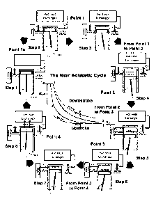
FIGs. 4a-4b show eight steps in an operational cycle of the engine. Its
corresponding p-V diagram
references the four points in the cycle. The steps are simplified so to better
explain and help visualize
the engine's operation. This disclosure describes an engine 400 with a
spinning valve frame
mechanism 130 having five openings feeding into the engine 400 and five
openings connecting the
working chamber 104 to the cooling reservoir 600. The valve frame 130
(rotating with its 30 inlet
openings 121) momentarily opens access once every 1/30 of a second. These five
openings are
housed in the valve frame 130, providing five shutter openings per revolution.
After the flow between
the cooling reservoir 600 and working chamber 104 closes, openings of the
inlet valve 121 align and
synchronize to open the flow from the high temperature/ pressure hot heat
exchange. For simplicity
and clarity, the steps herein focus on describing a single cylinder cycle of
the engine 400, using a
flywheel 145 to carry the momentum through the compression upstroke. However,
the engine
concept and the principles and lessons taught herein are in no way limited to
the configuration of a
21
Date recue/Date Received 2021-03-08
Attorney Docket No. 233-025
single cylinder engine. One major design concern for achieving optimum
performance has been the
configuration of the inlet valve 121 so as to supply sufficient flow of the
initial bolus into the engine
400. Note that the recommended speed of the engine is 1800 RMPs, meaning that
the crankshaft
141 of a single cylinder engine 400 will cycle 30 times a second. To achieve
the optimum bolus
condition in the expansion chamber 702, complete flow must be met within the
1/30 per second
timeframe. The steps shown in Figures 1- 5 describe the sequence of the flow
through the cycle.
FIG. 5 describes the first two steps. Step 1, as referenced to in the p-V
diagram of Figure 1, occurs
between points 4 and 1 (Stage 4) of the cycle, when the cycled working fluid
703 has been pushed
out of the engine 400 and received in the hot heat exchanger 500. Note here
that the inlet valve 121
from the hot heat exchanger 500 momentarily opens, allowing the high
temperature/pressure fluid
to enter the opened expansion chamber volume 702, injecting a fresh bolus of
working fluid 703,
energizing the next downstroke. Note that this action occurs at TDC or at
point 4 in the cycle and as
is shown in the p-V diagram. As this transfer of working fluid 703 reheats in
the hot heat exchanger
SOO, note that the hot heat exchanger 500 volume must be large enough so that
the influx of the
cooler working fluid 703 from the engine 400 does not significantly affect the
pressure/temperature
conditions in the larger hot heat exchanger SOO volume.
Step 2, as referenced to in the p-V
diagram of Figure 1, begins at point 1, at TDC, when the volume hot bolus
fills the expansion chamber
702 defined by shutting off the inlet valve port 121. That defined volume is
filled with the high
pressure/temperature working fluid 703 from the hot heat exchanger SOO.
Filling of the expansion
chamber 702 occurs with the momentary opening of the inlet valve 121 and the
alignment of the five
slit openings on the valve frame 130. The total effective area of the openings
of the inlet valve 121 is
15.56 cm2. After inlet valve 121 from the hot heat exchanger SOO to the
expansion chamber 702
closes, Step 3 begins with the working fluid 703 expanding, forcing the
working piston 103 downward.
The stroke moves from point 1 to point 2 (Stage 1) as shown on the p-V diagram
and in the schematic
drawings.
FIG. 6 shows steps 3 and 4. Step 3 begins after the inlet valve 121 closes,
when the working fluid 703
in the working chamber 104 is near-adiabatically expanded in isolation. This
expansion continues until
the working piston 103 almost reaches BDC. The isolated potential heat energy
in the working
22
Date recue/Date Received 2021-03-08
Attorney Docket No. 233-025
chamber 104 will be converted to real work output. Since a near-adiabatic
expansion is reversible,
the same real work input can be put back into the heat condition by
recompressing that fluid without
any outside interference or losses, converting the work back into heat
potential. For example, if an
equal amount of work is put back into the working chamber 104 through the anti-
work of a
recompression upstroke and if that recompression work on the working fluid 703
occurs without any
heat addition or lost occurring either through the walls of the working
chamber or otherwise, then
that active compression work would be converted back into its original heat
energy potential as was
at TDC. Step 4 shows that point right before the working piston 103 uncovers
the BDC unif low ports
to the cooling reservoir 600 at near BDC. Note that, to avoid recompression
during the upstroke with
equal work input, heat energy will be removed from the working chamber 104 at
BDC after the
working fluid 703 has expanded and before that working fluid 703 is
recompressed. Although the
temperature of the working fluid 703 drops with downstroke expansion, the heat
energy in that
working fluid 703 is not removed unless by some outside source. Without heat
removal,
recompression will require the same work input to return to the same level of
heat potential.
FIG. 7 shows steps 5 and 6. Step S begins when the pressurized cold fluid from
the cooling reservoir
600 is released into the working chamber 104. As the piston cycle bottoms out
at BDC and begins its
upstroke, the injected cold fluid, released from the cooling reservoir 600
into the working chamber
104, removes heat from the working fluid 703, bringing the temperature and
pressure down to the
low sink level, matching points 2 and 3 (Stage 2) on the p-V diagram and as
described in its drawings.
Step 6 begins with the compression upstroke at the cooler temperature and
lower pressure (with the
optimum heat removal). From point 3 to point 4 (Stage 3), the working fluid
703 is pressed into the
pump chamber volume 701. Likewise, the fluid 703 in the working chamber 104 is
pressed back into
the cooling reservoir 600 through the open port 122, located at the top rim of
the working cylinder
104. The access port 122 to the cooling reservoir 600 remains open during the
entire upstroke and as
is shown in the drawings of the upstroke from point 3 to point 4 (Stage 3).
Note that the fluid being
pressed into the cooling reservoir 600 is kept at the cool low temperature
level, thus removing the
heat energy so that the density in that fluid will rise (in the proposed
temperature bracket) to almost
twice the density of the higher energy working fluid 703 being compressed in
the pump chamber
volume 701. In raising the density, heat in the fluid is removed and that
cooled fluid is stored in the
23
Date recue/Date Received 2021-03-08
Attorney Docket No. 233-025
cooling reservoir, making ready for the next BDC injection and supercooling
before the next upstroke
recompression.
FIG. 8, shows step 7 and Step 8. Step 7 begins when the upstroke reaches the
point approaching TDC
wherein the pump volume is defined. At this position, the access port 122 to
the cooling reservoir
600 closes, and immediately, the working piston begins to act strictly as a
pump, pressing the volume
of working fluid inside the fluid pump 700 volume out from the engine through
the check valve 126
to the hot heat exchanger 500. Step 8 is the point when the pumping action has
been completed and
all the working fluid has been pushed back into the hot heat exchanger SOO.
The check valve 126
assures that the flow of the working fluid 703 will be unidirectional as the
working fluid 703 in the
cycle is forced back into the hot heat exchanger 500. With the working piston
103 acting as the
pumping mechanism, the injection of a new bolus from the hot heat exchanger
500 does not enter
into the engine 400 until the working piston has reached TDC (returning to
Step 1).
FIG. 9 describes the engine 400 configuration with its inlet port 121 to be
attached to the hot heat
exchanger 500 and an outlet check valve 126 (interior to the engine) which
also accesses the cycling
pump volume 701 (interior to the engine) into said hot heat exchanger SOO, as
previously patented.
The two connections 121 and 126 provide access to a balanced pressure
environment (interior to the
engine) but in intercourse with the high pressure state in the hot heat
exchanger wherein the working
fluid 703 (interior to the engine) is allowed to cycle through the engine 400
with minimum internal
resistance, converting an optimum portion of the heat energy into usable power
output 101. Note
that the operation of the inlet valve 121 and the connection valve 122 between
the cooling reservoir
and the working chamber is driven by a belt 800 connection to the main
crankshaft 141. Note that
cooling reservoir 600 is positioned conveniently and snuggly around the outer
wall of the working
cylinder 104 (interior to the engine) to prevent dead volumetric waste
pockets. Tubes 110 (interior
to the engine) of the cooling reservoir are cooled by either the ambient air
or water. Note that the
power output creates torque on crankshaft (driveshaft) 141 and on belt pully
143 which, through its
belt pully 806 connection, drives the inlet valve 121 (interior to the engine)
and the valve of the
cooling reservoir 122 (interior to the engine).
24
Date recue/Date Received 2021-03-08
Attorney Docket No. 233-025
FIG. 10 is a detail side view showing the operation of the valve frame 130
that houses the inlet valve
121. As shown, the valve frame 130 is driven by the bevel gears 151 and 152
drive the rotating inlet
valve 121, and the valve connection 122 between the cooling reservoir 600 (not
in the figure) and
working chamber 104 (not in the figure). As explained earlier, the valve frame
130 rotates 6 times per
second to open the inlet valve 121 30 times in that second in sync with the 30
rotations per second
of the main crankshaft 141 (not in the figure). It shows the port 122 between
the cooling reservoir
600 and working chamber 104 that is open during almost the entire upstroke so
as to optimize the
flow back and forth, as explained in item 2 in the section called The Valving
Interchange in the
Working Chamber and the Flow Capacity of the Disclosed Model. Note that the
connecting belt 800
between the crankshaft 141 (not in the figure) and the axis of the small bevel
gear 152 has a one to
one pully ratio.
FIG. 11 further describes, with an yz plane sectional cut, the interior
workings of the engine 400 and
specifically the TDC sequence that ensures the effective closing of check
valve 125 during the effective
closing of pump 700 in sequence with the closing of connection valve 122 and
opening of the inlet
valve 121. The figure shows that, as the working piston 103 approaches the
near TDC position, the
connecting valve 122 to the cooling reservoir 600 closes, allowing the pump
700 to begin closing.
FIG. 12 shows the engine 400 stripped of its primary outer static body parts
401, showing the interior
moving parts such as the working piston 103 and its power train, and valve
frame 130 train. The
power train includes the flywheel 145 and power pully 144. The valve frame
train includes the belt
800 connection to the valve frame 130. The gear train to the valve frame 130
and valves 121 and 122
are driven by the rotating cam rod 801. The gear train operates the valve
frame mechanism 130 that
houses both the inlet valve 121 between the hot heat exchanger 500 (not in the
figure) and expansion
chamber 701 of the working chamber 104, and the connecting valve 122 between
the cooling
reservoir 600 and working chamber 104. The figure also shows the flapper plate
128 of the exhaust
check valve 126 that ensures unidirectional flow of the working fluid 703 from
the fluid pump volume
700 out of exhaust port 123 to the hot heat exchanger SOO,
Date recue/Date Received 2021-03-08
Attorney Docket No. 233-025
FIG. 13 shows a cross-sectional elevation of the crankcase 141 and the power
train, describing the
transfer of power out of the engine, using a magnetic coupling 142 so as to
prevent leakage along the
main driveshaft 141 from the interior of the engine body to the outside. Note
that the magnetic
coupling 142 includes a seal wall between the outer magnetic ring and the
inner magnetic. Note that
the timing pulley 143 (connected to the timing belt) is mounted on the shaft
141. Note the flywheel
145 and power output pulley 144 is mounted on the shaft 141.
FIG. 14a and 14b shows side and front elevations of the engine 400, but with
two different designs of
the piston ¨ one that uses a bellows seal and the other that has two groups of
piston rings mounted
at the upper and the lower face of the piston's cylindrical surface. The
figure further describes the
configuration of the engine, defining the relationship of the static body 401
parts to the moving parts
and specifically focusing on the four valves 121, 122, 124, and 126 and the
five volumes 701, 702,
104, 600, and 500 that control the cycle. The figure gives a detailed visual
description of the operation
of the four valves 121, 122, 124, and 125 that directly interact with the
working chamber 104 during
the cycle, creating the optimum sequential operational function of the valves
in that working
chamber 104, and looking at the exit outlet port 123 that returns the working
fluid 703 back to the
hot heat exchanger 500. As mentioned above, in showing the two designs of the
working piston 103,
the piston on the left will use a bellows as a seal and the piston shown on
the right will use two groups
of 0-rings at the top and bottom rims of the outer parameter. The figure shows
the valve frame 130
that houses the inlet valve 121 that accesses the injected high
temperature/pressure bolus of working
fluid into the engine 400. They show the connecting valve 122 between the
cooling reservoir 600 and
working chamber 104. They show the BDC operation of the unif low valve 124
between the cooling
reservoir 600 and working chamber 104. As the working piston 103 nears BDC,
simultaneously the
near TDC connection valve between the cooling reservoir 600 and the working
cylinder 104 opens.
The figure shows the relationship of the cooling reservoir 600 to the working
piston 103 as the BDC
operation opens the BDC unif low valve. Note that, as the working piston 103
approaches BDC, BDC
ports 124 to the cooling reservoir 600 are uncovered, allowing the cold
pressurized fluid in the cooling
reservoir 600 to rush out and supercool the working fluid 703 in the working
chamber 104 at BDC.
Also, the figure shows the unidirectional flow from the pump volume 701
cavity, specifically showing
26
Date recue/Date Received 2021-03-08
Attorney Docket No. 233-025
the operation of the unidirectional check valve outlet port 123 where the
working fluid exits the
engine 400 and enters back into the hot heat exchanger 500.
FIG. 15 is a sectional view, cutting through with a plane yz, describing the
interior configuration of
the engine and specifically focusing on the actions of TDC and BDC valves 121,
122, and 124. The
injected hot working fluid 703, that enters the expansion chamber 702 at TDC,
is isolated when the
inlet port 121 closes and the working fluid 703 expands, forcing downward the
working piston 103.
The expansion force causes the crankshaft 141 to rotate, which causes the
engine output 101 and
rotates the belt connection 800 to the gear train to the valve frame 130,
creating the appropriate
sequential operation of the valves occurring during the cycle. As the working
piston 103 approaches
BDC, port 124 (located at BDC) and port 122 (located at TDC) open to the
cooling reservoir 600,
simultaneously releasing the contained pressurized cold fluid from the cooling
reservoir 600 into the
working chamber 104. The released fluid at BDC supercools the working fluid
703 in the working
chamber 104 at BDC before recompression. The working fluid 703 and the fluid
from the cooling
reservoir are mixed together. This mixture is then near-isothermally
recompressed back into the
cooling reservoir 600 while the remaining working fluid 703 is near-
adiabatically compressed into the
fluid pump volume 700. Although the BDC port valve 124 closes at the beginning
of the working piston
103 upstroke, valve 122 between the working chamber 104 and cooling reservoir
600 remains open
during almost the entire upstroke before defining the pump chamber volume 700.
Right before
reaching the pump volume 700, valve 122 closes. The pump volume 701 closes,
pressing the cycling
working fluid 703 back into the high pressure/temperature hot heat exchanger
SOO. At TDC, the inlet
valve 121 opens, accessing another high energy bolus into the opening
expansion chamber 702.
FIG. 16 also shows specifically the TDC valve operation and inner workings of
the inlet valve 121 and
connection valve 122. Inlet valve 121 is momentarily open at TDC for injecting
the bolus. The figure
also shows the workings of the valve 122, connecting the cooling reservoir 600
(not in the figure) to
the working chamber 104 (not in the figure), opened during almost the entire
upstroke. As explained
above, both inlet valve 121 and connection valve 122 are mounted on the valve
frame 130, having a
conical frustum shape as shown in the isometric view and rotating under the
gear power train which
is driven by the crankshaft 141 connected to belt 800. FIG. 12a in this figure
shows a detail of port
122 as it rotates on the valve frame 130, opens at BDC and closes immediately
before valve port 121
opens at TDC. Note that the body frame 401 (surrounding and sandwiching the
valve frame 130)
27
Date recue/Date Received 2021-03-08
Attorney Docket No. 233-025
provides a seat for valve frame 130. Note that bevel gear 152 is mounted on
the valve frame 130
which is driven by bevel gear 151. To prevent friction between the contacts of
the valve frame 130
and the engine body frame 401, at the bottom surface of the valve frame 130,
ball bearings 107 are
seated to minimize contact between the body 401 and valve frame 130. The ring
portion of the valve
frame 130 rides on these ball bearings 107. The figure also shows a top view
of the inner workings of
the inlet valve 121, and the connection valve 122 between the cooling
reservoir 600 and working
chamber 104 as explained above.
The volumes are defined and distinguished by the sequence of the opening and
closing of the
inlet 121 and connecting 122 valves. For example, the opening of the inlet
valve 121 at the beginning
of the downstroke near-isothermally feeds hot working fluid into the opening
expansion volume 702.
When that inlet valve 121 is closed, the downstroke becomes the near-adiabatic
expansion
downstroke of the work output during cycle. Likewise, the upstroke is the near-
adiabatically
compressed portion of the work input as long as the connecting valve 122
between the cooling
reservoir and working cylinder is open. When that connecting valve closes, the
remaining volume in
the working cylinder become the pump volume 700 during the upstroke to TDC and
thus defines that
pump volume and becomes that pump volume (filled with working fluid) that is
pressed near-
isothermally back to the high pressure/temperature level of the hot heat
exchanger.
FIG. 17 is a sectional cut of the engine, using a xy axis chamber 701. As the
pump chamber 701 closes,
the working fluid 703 (not shown in the figure) will be pushed out of the
engine 400 through check
valve 126 and into the hot heat exchanger 500 (not in the figure). Note that
the closed cooling
reservoir 600 will contain its high pressure, cooled fluid until reaching BDC
for the next BDC release
into the working chamber 104, supercooling of the expanded working fluid 703.
Additionally, FIG. 13
shows the compact internal configuration of the internal volumes affecting the
cycling process of the
engine 400. The interior volumes, that contain the working fluid 703 flowing
through the cycling
system, are compactly configured wherever possible so as to eliminate losses
or wasted energy due
to residual volumetric pockets of uncycled working fluid. The relevant volumes
are designed
compacted so as to minimize any dead volumetric pockets that are not being
cycled through the
engine 400 during the disclosed action. These dead volumes are minimized in
order to optimize the
thermal to work conversion of the system. All other volumes outside of these
four listed volumes are
28
Date recue/Date Received 2021-03-08
Attorney Docket No. 233-025
not part of nor are have relevant to the above listed internal volumes that
affect the engine efficiency.
Since minimizing the residual dead volumetric pockets will significantly
improve the cycle efficiency
of the engine, the means for achieving this improvement must also be herein
included as proprietary
disclosures.
FIG. 18 shows the operation of the cooling reservoir 600 wherein a liquid
coolant 601 such as cold
water or ammonia water is sprayed onto the cooling coils and the phase change
is caused through
the evaporation of the liquid coolant, which is converted from a liquid into a
vapor, causing optimum
heat absorption in the cooling process. The coolant 601 enters in an entrance
tube into a chamber as
a liquid and is sprayed through rows of mini spray nozzles 606 into the
cooling reservoir casing 602
directly onto the cooling coils 110. The coolant will vaporize, and the phase
change will cause
significant heat absorption, drawn from the compressed working fluid 703 in
the engine. The
expansion of the vapor will rapidly force the vapor out of the cooling
reservoir through opening 607
and out outlet tube 604. Note that the pressurize working fluid in the cooling
coils 110 passes through
the connecting valve 122 and that the cooling period of time is extended while
the working fluid 702
is held in containment during the downstroke (expansion stroke) of the cycle.
FIG. 19 shows the shutoff valve 201 between the engine 400 and the containment
furnace 900. When
the engine powers down and stops, to prevent flooding of the engine 400, a
shutoff valve 201
completely shuts off flow through openings 203 between the engine 400 and the
containment
furnace 900. Instead the shutoff valve 201 redirects the flow so as to open up
passage at 202 between
the exhaust line and the inlet line to the engine 400, allowing the working
fluid in the engine 400 to
circulate during startup in order to minimize the internal resistance. The
engine 400 is started by the
power of the alternator (the generator/starter motor). Once the momentum of
the flywheel of the
engine builds up, the valve 201 will open up allowing hot working fluid in the
hot heat exchanger SOO
to flow into and drive the engine 400.
FIG. 20 shows the operation of the snap shut valve mechanism 140. The large
bevel gear 151 around
the ring of the valve frame 130 will rotate at a constant speed while the
valve frame 130 itself,
although spinning on the same central axis, has a torsion spring bias 105 or
136 that allows the valve
29
Date recue/Date Received 2021-03-08
Attorney Docket No. 233-025
openings 133 and 134 to be slightly pulled back ensuring the opening is wider
and the closing is more
deliberate. A torsion spring 135 or 136 allows the valve opening 133 or 134 to
be extended to the
point of deliberate closing. The valve frame 130 is slightly held back as the
biased swivel resister 137
rides over an ramp 154 and 155 obstacle, because the torsion spring 135 or 136
is bias so the valves
133 or 134 are in the open position, will snap shut at the exact point
defining the expansion volume
702 and the pump volume 701, optimizing the filling of the expansion volume
702 for optimum
volumetric definite for the near-adiabatic expansion, and optimizing the
definition of the pump
volume 701 for precise pumping of an equal quantity of working fluid 703 as
the bolus injected into
the expansion chamber 702 of the engine at the beginning of the cycle.
Terms
1000 ¨ the thermal system, called the Gas-Tricity, including the near-
adiabatic engine and
containment furnace
400 ¨ engine
401 ¨ engine body frame
402¨ body frame for the valve frame, having conical frustum shape
500¨ a heat exchanger
600 a cooling reservoir
601 ¨ cooling water
602 ¨ cooling reservoir casing
603 ¨ inlet tube
604 ¨ outlet tube
605 ¨ vaporized coolant
606 ¨ rows of mini spray nozzles
607 ¨ opening to the outlet tube
700 ¨ a fluid pump
701 ¨ pump chamber
702¨ expansion chamber
703 ¨ working fluid
110 ¨ tubes of a cooling chamber
Date recue/Date Received 2021-03-08
Attorney Docket No. 233-025
101 ¨output mechanism
121 ¨inlet port
122¨ port to and from the cooling reservoir
123 ¨engine outlet port
124¨ BDC port to cooling reservoir
126 ¨check valve between the pump chamber and the heat exchanger
128 ¨flapper plate of valve 126
129 ¨check valve between the crankcase volume 140 and the cooling reservoir
volume 600
103¨ power piston
104 ¨the working chamber
105¨ power piston bellows
106 ¨connecting rod
107¨ ball bearings for seat of valve frame for valves 121 and 122, having a
conical frustum shape
108 ¨ piston rings
100¨ upstroke compression chamber in the working chamber
800¨ belt between the crank shaft and valve mechanism
806 ¨valve mechanism pulley
140 ¨crankcase volume
141 ¨crankshaft
,
142¨ crankshaft magnetic coupling
143¨crankshaft belt pully
144¨ main crankshaft pully
145¨ main crankshaft flywheel
130 ¨valve frame
131 ¨valve frame out wall track
132¨ ramp resister
133 ¨the inlet valve ports on the valve frame
134 ¨the cooling reservoir valve ports on the valve frame
135 ¨torsion spring for valve frame and bevel gear
136¨ compression spring for valve frame and bevel gear
31
Date recue/Date Received 2021-03-08
Attorney Docket No. 233-025
137 ¨ swivel resister spring loaded
138¨ valve frame mini cam drag resisters
139¨ drag resister spring
140 ¨the snap shut mechanism
150¨ bevel and spur gears
151¨ bevel gear for the valve frame
152¨ small bevel gear and shaft
900¨ containment furnace
901 ¨furnace inner exchanger coils
902 ¨furnace outer casing
903 ¨gas facet
904 ¨furnace hot outlet
905 ¨furnace cooler inlet
906 ¨flue outlet
300¨ magnetic coupling
301 ¨.interior shaft of magnetic coupling
302¨ exterior shaft of magnetic coupling
303¨ membrane of magnetic coupling
201¨ shutoff valve between the heat exchanger and the engine
202¨ loop port
203¨ connection port
32
Date recue/Date Received 2021-03-08