Note: Descriptions are shown in the official language in which they were submitted.
APPARATUSES AND METHODS FOR MANIPULATING CURVED SHEETS
FIELD
This disclosure relates to manufacturing assemblies of curved components such
as
in the aircraft industry and more particularly to the manipulation of curved
sheets in
the manufacturing of such assemblies, using magnetic components.
BACKGROUND
Curved sheets are conventionally coupled together by overlapping edges of
the curved sheets to form lap joints, fastened together, e.g., with rivets.
Curved
sheets are commonly coupled in this manner in aerospace applications and, in
such
an example, the curved sheets are metallic curved sheets and may form, e.g.,
part of
a fuselage, a wing, a stabilizer or other aerodynamic surface. Using lap
joints and/or
splice plates when coupling curved sheets together requires additional
material to
provide overlap of the curved sheets, thereby increasing the weight and cost
of the
assembly.
SUMMARY
Accordingly, apparatuses and methods that reduce the cost of manufacturing
of assemblies of curved sheets and the weight of such assemblies are desired.
One example described herein relates to an apparatus for manipulating a
plurality of curved sheets. Each of the plurality of curved sheets includes an
upper
surface and a lower surface. The apparatus includes tooling to be coupled to
the
upper surface of each of the plurality of curved sheets. The tooling is
capable of
1
Date Recue/Date Received 2021-02-09
moving the plurality of curved sheets relative to each other and abutting the
plurality
of curved sheets so that the upper surface of each of the plurality of curved
sheets is
coextensive with a virtual arcuate surface.
In one example of the apparatus, which may include at least a portion of the
subject matter of any of the preceding and/or following examples, the virtual
arcuate
surface includes no inflection points along a cross-section thereof
perpendicular to a
virtual straight line coextensive with the virtual arcuate surface.
In one example of the apparatus, which may include at least a portion of the
subject matter of any of the preceding and/or following examples, the
plurality of
curved sheets, abutted so that the upper surface of each of the plurality of
curved
sheets is coextensive with the virtual arcuate surface, subtend a central
angle
between about 2 degrees and about 270 degrees in a virtual plane perpendicular
to
a virtual straight line coextensive with the virtual arcuate surface.
In one example of the apparatus, which may include at least a portion of the
subject matter of any of the preceding and/or following examples, the
plurality of
curved sheets, abutted so that the upper surface of each of the plurality of
curved
sheets is coextensive with the virtual arcuate surface, subtend a central
angle of
about 180 degrees in a virtual plane perpendicular to a virtual straight line
coextensive with the virtual arcuate surface.
In one example of the apparatus, which may include at least a portion of the
subject matter of any of the preceding and/or following examples, the tooling
includes at least one holder to be removably coupled to the upper surface of
at least
one of the plurality of curved sheets.
In one example of the apparatus, which may include at least a portion of the
subject matter of any of the preceding and/or following examples, the at least
one
holder extends in a non-perpendicular direction relative to weight vectors of
the
plurality of curved sheets.
2
Date Recue/Date Received 2021-02-09
In one example of the apparatus, which may include at least a portion of the
subject matter of any of the preceding and/or following examples, the at least
one
holder extends in a substantially parallel direction relative to weight
vectors of the
plurality of curved sheets.
In one example of the apparatus, which may include at least a portion of the
subject matter of any of the preceding and/or following examples, the at least
one
holder extends in a substantially perpendicular direction relative to weight
vectors of
the plurality of curved sheets.
In one example of the apparatus, which may include at least a portion of the
subject matter of any of the preceding and/or following examples, the at least
one
holder has a selectively variable length.
In one example of the apparatus, which may include at least a portion of the
subject matter of any of the preceding and/or following examples, the tooling
includes at least one first holder and at least one second holder.
In one example of the apparatus, which may include at least a portion of the
subject matter of any of the preceding and/or following examples, the at least
one
first holder and the at least one second holder extend in different
directions.
In one example of the apparatus, which may include at least a portion of the
subject matter of any of the preceding and/or following examples, the tooling
is
reconfigurable.
In one example, which may include at least a portion of the subject matter of
any of the preceding and/or following examples, the apparatus also includes a
processing station facing the lower surfaces of the plurality of curved
sheets.
In one example of the apparatus, which may include at least a portion of the
subject matter of any of the preceding and/or following examples, the
processing
station includes a subtractive-manufacturing apparatus.
3
Date Recue/Date Received 2021-02-09
In one example of the apparatus, which may include at least a portion of the
subject matter of any of the preceding and/or following examples, the
subtractive-
manufacturing apparatus includes a drilling apparatus.
In one example of the apparatus, which may include at least a portion of the
subject matter of any of the preceding and/or following examples, the
processing
station includes a laser-welding apparatus.
In one example, which may include at least a portion of the subject matter of
any of the preceding and/or following examples, the apparatus also includes a
carriage configured to move relative to the plurality of curved sheets and the
processing station is coupled to and moveable with the carriage.
In one example of the apparatus, which may include at least a portion of the
subject matter of any of the preceding and/or following examples, the
processing
station includes a friction-stir-welding apparatus.
In one embodiment, there is provided a method of manufacturing an assembly
including a first curved sheet and a second curved sheet, the first curved
sheet
including a first upper surface and a first edge, the second curved sheet
including a
second upper surface and a second edge. The method involves supporting the
first
upper surface of the first curved sheet and the second upper surface of the
second
curved sheet. Supporting the first upper surface and the second upper surface
involves extending first holders from a first side of a housing toward a first
exterior of
the first curved sheet, wherein the first holders have first selectively
variable lengths,
and coupling the first holders to the first exterior of the first curved
sheet, wherein
when the first holders are coupled to the first exterior of the first curved
sheet at least
two of the first holders have different first lengths. Supporting the first
upper surface
and the second upper surface further involves extending second holders from a
second side of the housing toward a second exterior of the second curved
sheet.
The second holders have second selectively variable lengths. Supporting the
first
upper surface and the second upper surface further involves coupling the
second
4
Date Recue/Date Received 2021-02-09
holders to the second exterior of the second curved sheet, wherein when the
second
holders are coupled to the second exterior of the second curved sheet at least
two of
the second holders have different second lengths. The method further involves
abutting the first edge of the first curved sheet and the second edge of the
second
curved sheet so that the first upper surface of the first curved sheet and the
second
upper surface of the second curved sheet are coextensive with a virtual
arcuate
surface. The method further involves positioning a processing station to face
a first
lower surface of the first curved sheet and a second lower surface of the
second
curved sheet. The positioning of the processing station involves positioning a
friction-stir-welding apparatus to face the first lower surface and the second
lower
surface, locating a first magnetic member relative to the first upper surface
of the first
curved sheet adjacent the first edge of the first curved sheet;. The method
further
involves locating a second magnetic member relative to the first lower surface
of the
first curved sheet adjacent the first edge. The method further involves
locating a
third magnetic member relative to the second upper surface of the second
curved
sheet adjacent the second edge of the second curved sheet. The method further
involves locating a fourth magnetic member relative to the second lower
surface of
the second curved sheet adjacent the second edge. The method further involves
magnetically coupling the first magnetic member to the second magnetic member
and the third magnetic member to the fourth magnetic member after abutting the
first
edge and the second edge, wherein the second magnetic member and the fourth
magnetic member are coupled to and moveable with the processing station
relative
to the first curved sheet and the second curved sheet. The method further
involves
welding the first edge of the first curved sheet and the second edge of the
second
curved sheet together to create a weldment after abutting the first edge and
the
second edge.
In another embodiment, there is provided a method of manufacturing an
assembly including a first curved sheet, a second curved sheet, and a third
curved
sheet, the first curved sheet including a first upper surface and a first
edge, the
second curved sheet including a second upper surface, a second edge, and a
third
5
Date Recue/Date Received 2021-02-09
edge, and the third curved sheet including a third upper surface and a fourth
edge.
The method involves supporting the first upper surface of the first curved
sheet, the
second upper surface of the second curved sheet, and the third upper surface
of the
third curved sheet, wherein supporting the first upper surface, the second
upper
surface. The third upper surface involves extending first holders from a first
side of a
housing toward a first exterior of the first curved sheet, wherein the first
holders have
first selectively variable lengths. The method further involves coupling the
first
holders to the first exterior of the first curved sheet, wherein when the
first holders
are coupled to the first exterior of the first curved sheet at least two of
the first
holders have different first lengths. The method further involves extending
second
holders from a second side of the housing toward a second exterior of the
second
curved sheet, wherein the second holders have second selectively variable
lengths/
The method further involves coupling the second holders to the second exterior
of
the second curved sheet, wherein when the second holders are coupled to the
second exterior of the second curved sheet at least two of the second holders
have
different second lengths. The method further involves extending third holders
from a
third side of the housing toward a third exterior of the third curved sheet,
wherein the
third holders have third selectively variable lengths. The method further
involves
coupling the third holders to the third exterior of the third curved sheet,
wherein,
when the third holders are coupled to the third exterior of the third curved
sheet, at
least two of the third holders have different third lengths. The method
further
involves abutting the first edge and the second edge so that the upper surface
of the
first curved sheet and the second upper surface of the second curved sheet are
coextensive with a virtual arcuate surface. The method further involves
abutting the
third edge of the third curved sheet and the fourth edge of the third curved
sheet so
that the second upper surface, and the third upper surface are coextensive
with the
virtual arcuate surface. The method further involves positioning a processing
station
to face a first lower surface of the first curved sheet and a second lower
surface of
the second curved sheet. The positioning of the processing station further
includes
positioning a friction-stir-welding apparatus to face the first lower surface
and the
6
Date Recue/Date Received 2021-02-09
second lower surface, and locating a first magnetic member relative to the
first upper
surface of the first curved sheet adjacent the first edge of the first curved
sheet. The
positioning of the processing station further includes locating a second
magnetic
member relative to the first lower surface of the first curved sheet adjacent
the first
edge, and locating a third magnetic member relative to the second upper
surface of
the second curved sheet adjacent the second edge of the second curved sheet.
The
positioning of the processing station further includes locating a fourth
magnetic
member relative to the second lower surface of the second curved sheet
adjacent
the second edge, and magnetically coupling the first magnetic member to the
second magnetic member and the third magnetic member to the fourth magnetic
member after abutting the first edge and the second edge, wherein the second
magnetic member and the fourth magnetic member are coupled to and moveable
with the processing station relative to the first curved sheet and the second
curved
sheet. The positioning of the processing station further includes welding the
first
edge and the second edge together to create a weldment after abutting the
first edge
and the second edge, and welding the third edge and the fourth edge together
to
create a weldment after abutting the third edge and the fourth edge.
In another embodiment, there is provided a method of manufacturing an
assembly including a first curved sheet and a second curved sheet, the first
curved
sheet including a first upper surface and a first edge, the second curved
sheet
including a second upper surface and a second edge. The method involves
supporting the first upper surface of the first curved sheet and the second
upper
surface of the second curved sheet. Supporting the first upper surface and the
second upper surface involves extending first holders from a first side of a
housing
toward a first exterior of the first curved sheet. The first holders have
first selectively
variable lengths. The method further involves coupling the first holders to
the first
exterior of the first curved sheet, wherein, when the first holders are
coupled to the
first exterior of the first curved sheet at least two of the first holders
have different
first lengths. The method further involves extending second holders from a
second
side of the housing toward a second exterior of the second curved sheet,
wherein
7
Date Recue/Date Received 2021-02-09
the second holders have second selectively variable lengths, and coupling the
second holders to the second exterior of the second curved sheet, wherein,
when
the second holders are coupled to the second exterior of the second curved
sheet, at
least two of the second holders have different second lengths. The method
further
involves abutting the first edge of the first curved sheet and the second edge
of the
second curved sheet so that the first upper surface of the first curved sheet
and the
second upper surface of the second curved sheet are coextensive with a virtual
arcuate surface. The method further involves positioning a processing station
to
face a first lower surface of the first curved sheet and a second lower
surface of the
second curved sheet. The positioning of the processing station further
involves
positioning a friction-stir-welding apparatus to face the first lower surface
and the
second lower surface, and locating a first magnetic member relative to the
first upper
surface adjacent the first edge. The positioning of the processing station
further
involves locating a second magnetic member relative to the first lower surface
adjacent the first edge, and locating a third magnetic member relative to the
second
upper surface adjacent the second edge. The positioning of the processing
station
further involves locating a fourth magnetic member relative to the second
lower
surface adjacent the second edge. The positioning of the processing station
further
involves magnetically coupling the first magnetic member to the second
magnetic
member and the third magnetic member to the fourth magnetic member after
abutting the first edge and the second edge, wherein the first magnetic member
and
the second magnetic member are each curved to conform to the first curved
sheet
and the third magnetic member and the fourth magnetic member are each curved
to
conform to the second curved sheet, and wherein the second magnetic member and
the fourth magnetic member are coupled to and moveable with the processing
station relative to the first curved sheet and the second curved sheet. The
positioning of the processing station further involves welding the first edge
of the first
curved sheet and the second edge of the second curved sheet together to create
a
weldment after abutting the first edge and the second edge.
7a
Date Recue/Date Received 2021-02-09
In another embodiment, there is provided an apparatus for manipulating a
plurality of curved sheets, wherein the plurality of curved sheets comprises a
first
curved sheet and a second curved sheet, wherein the first curved sheet
comprises a
first upper surface, a first lower surface, and a first edge, and wherein the
second
curved sheet comprises a second upper surface, a second lower surface, and a
second edge. The apparatus includes a housing, and first holders extending
from
the housing in a first direction, wherein the first holders are configured to
be
removably coupled to the first upper surface of the first curved sheet, and
wherein
the first holders are individually movable along the first direction to
position the first
curved sheet such that the first upper surface is coextensive with a first
portion of a
virtual arcuate surface. The apparatus further includes second holders
extending
from the housing in a second direction, wherein the second holders are
configured to
be removably coupled to the second upper surface of the second curved sheet,
and
wherein the second holders are individually movable along the second direction
to
position the second curved sheet such that the second upper surface is
coextensive
with a second portion of the virtual arcuate surface and such that the second
edge is
abutting the first edge. The apparatus further includes a carriage disposed in
a
facing relationship with the first lower surface of the first curved sheet and
the
second lower surface of the second curved sheet, wherein the carriage is
operable
to move along the first edge and the second edge of the first curved sheet and
the
second curved sheet when the first edge and the second edge are abutting one
another. The apparatus further includes a processing station coupled to the
carriage, wherein the processing station is movable with the carriage, and
wherein
the processing station comprises a welding apparatus operable to weld the
first edge
and the second edge as the carriage moves along the first edge of the first
curved
sheet and along the second edge of the second curved sheet when the first edge
and the second edge are abutting one another. The apparatus further includes a
first magnetic member, configured to be positioned on the first upper surface
of the
.. first curved sheet adjacent the first edge. The apparatus further includes
a second
7b
Date Recue/Date Received 2021-02-09
magnetic member coupled to the carriage, wherein the second magnetic member
magnetically couples to the first magnetic member when the first magnetic
member
is positioned on the first upper surface of the first curved sheet, and
wherein the
second magnetic member is movable with the carriage. The apparatus further
includes a third magnetic member, configured to be positioned on the second
upper
surface of the second curved sheet adjacent the second edge, and a fourth
magnetic
member coupled to the carriage, wherein the fourth magnetic member
magnetically
couples to the third magnetic member when the third magnetic member is
positioned
on the second upper surface of the second curved sheet, and wherein the fourth
.. magnetic member is movable with the carriage.
In another embodiment, there is provided an apparatus for manipulating a
plurality of curved sheets, wherein the plurality of curved sheets comprises a
first
curved sheet and a second curved sheet, wherein the first curved sheet
comprises a
first upper surface, a first lower surface, and a first edge, and wherein the
second
curved sheet comprises a second upper surface, a second lower surface, and a
second edge. The apparatus includes a housing; first holders extending from
the
housing in a first direction, wherein the first holders are configured to be
removably
coupled to the first upper surface of the first curved sheet, and wherein the
first
holders are individually movable along the first direction to position the
first curved
sheet in a first position or in a second position, wherein the first upper
surface of the
first curved sheet is coextensive with a first portion of a virtual arcuate
surface in the
second position; second holders extending from the housing in a second
direction.
The second holders are configured to be removably coupled to the second upper
surface of the second curved sheet, and wherein the second holders are
individually
movable along the second direction to position the second curved sheet in a
third
position or in a fourth position, wherein the second edge of the second curved
sheet
is spaced apart from the first edge when the first curved sheet is in the
first position
and the second curved sheet is in the third position. The second upper surface
of
the second curved sheet is coextensive with a second portion of the virtual
arcuate
.. surface in the fourth position. The first edge is abutting the second edge
when the
7c
Date Recue/Date Received 2021-02-09
first curved sheet is in the second position and the second curved sheet is in
the
fourth position; a carriage disposed in a facing relationship with the first
lower
surface of the first curved sheet and the second lower surface of the second
curved
sheet. The carriage is operable to move along the first edge of the first
curved sheet
and the second edge of the second curved sheet when the first curved sheet and
the
second curved sheet are, respectively, in the second position and the fourth
position;
a processing station coupled to the carriage. The processing station is
movable with
the carriage along the first edge of the first curved sheet and the second
edge of the
second curved sheet when the first curved sheet and the second curved sheet
are,
respectively, in the second position and the fourth position. The processing
station
includes a subtractive-manufacturing apparatus operable to process one of the
first
edge and the second edge when the first curved sheet is in the first position
and the
second curved sheet is in the third position. The processing station further
includes
a welding apparatus operable to weld the first edge and the second edge as the
carriage moves along the first edge and the second edge when the first curved
sheet
and the second curved sheet are, respectively, in the second position and the
fourth
position and the first edge and the second edge abut each other. The
processing
station further includes a first magnetic member, configured to be positioned
on the
first upper surface of the first curved sheet adjacent the first edge, and a
second
magnetic member coupled to the carriage, wherein the second magnetic member
magnetically couples to the first magnetic member when the first magnetic
member
is positioned on the first upper surface of the first curved sheet, and
wherein the
second magnetic member is movable with the carriage. The processing station
further includes a third magnetic member, configured to be positioned on the
second
upper surface of the second curved sheet adjacent the second edge. The
processing station further includes a fourth magnetic member coupled to the
carriage, wherein the fourth magnetic member magnetically couples to the third
magnetic member when the third magnetic member is positioned on the second
upper surface of the second curved sheet, and wherein the fourth magnetic
member
.. is movable with the carriage.
7d
Date Recue/Date Received 2021-02-09
In another embodiment, there is provided an apparatus for manipulating a
plurality of curved sheets. The apparatus includes tooling to be coupled to
the upper
surface of each of the plurality of curved sheets. The tooling is capable of
moving the
plurality of curved sheets relative to each other to abut the plurality of
curved sheets so
that the upper surface of each of the plurality of curved sheets is
coextensive with a
virtual arcuate surface. The apparatus further includes a processing station
facing
lower surfaces of the plurality of curved sheets. The processing station
includes a
friction-stir-welding apparatus. The apparatus further includes a first
magnetic
member to be associated with the upper surface of a first curved sheet of the
plurality of curved sheets adjacent an edge of the first curved sheet. The
apparatus
further includes a second magnetic member associated with a lower surface of
the
first curved sheet adjacent the edge of the first curved sheet. The apparatus
further
includes a third magnetic member to be associated with the upper surface of a
second curved sheet of the plurality of curved sheets and adjacent an edge of
the
second curved sheet. The apparatus further includes a fourth magnetic member
associated with the lower surface of the second curved sheet adjacent the edge
of
the second curved sheet. The first magnetic member is to be magnetically
coupled
to the second magnetic member and the third magnetic member is to be
magnetically coupled to the fourth magnetic member with the edge of the first
curved
sheet and the edge of the second curved sheet abutting each other.
In another embodiment, there is provided a method of manufacturing an
assembly including a first curved sheet and a second curved sheet, the first
curved
sheet including a first upper surface and a first edge, the second curved
sheet
including a second upper surface and a second edge. The method involves
supporting the first upper surface and the second upper surface, and abutting
the first
edge and the second edge so that the first upper surface and the second upper
7e
Date Recue/Date Received 2021-02-09
surface are coextensive with a virtual arcuate surface. The method further
involves
welding the first edge and the second edge together to create a weldment after
abutting the first edge and the second edge, and providing a processing
station to face
a first lower surface of the first curved sheet and a second lower surface of
the second
curved sheet. The positioning of the processing station further includes
positioning a
friction-stir-welding apparatus to face the first lower surface and the second
lower
surface. The method further involves locating a first magnetic member relative
to
the first upper surface to be adjacent the first edge, and locating a second
magnetic
member relative to the first lower surface to be adjacent the first edge. The
method
further involves locating a third magnetic member relative to the second upper
surface to be adjacent the second edge, and locating a fourth magnetic member
relative to the second lower surface to be adjacent the second edge. The
method
further involves magnetically coupling the first magnetic member to the second
magnetic member and the third magnetic member to the fourth magnetic member
after
abutting the first edge and the second edge.
BRIEF DESCRIPTION OF THE DRAWINGS
Having thus described examples of the disclosure in general terms, reference
will now be made to the accompanying drawings, which are not necessarily drawn
to
scale, and wherein like reference characters designate the same or similar
parts
throughout the several views, and wherein:
Fig. 1 is a flow diagram of aircraft production and service methodology;
Fig. 2 is a block diagram of an aircraft;
Fig. 3 is a perspective view of a portion of a vehicle such as, for example,
an
aircraft, according to an aspect of the present disclosure.
Fig. 4 is a block diagram of an apparatus, according to an aspect of the
present disclosure;
7f
Date Recue/Date Received 2021-02-09
Fig. 5 is a schematic elevational view of an apparatus including tooling for
supporting a plurality of curved sheets, according to an aspect of the present
disclosure;
Fig. 6 is an elevational view of the apparatus shown in Fig. 5, according to
an
aspect of the present disclosure;
Fig. 7 is a schematic elevational view of the apparatus shown in Fig. 5,
according to an aspect of the present disclosure;
7g
Date Recue/Date Received 2021-02-09
Fig. 8 is a schematic elevational view of an apparatus including tooling for
supporting a plurality of curved sheets, according to an aspect of the present
disclosure;
Fig. 9 is a schematic elevational view of an apparatus, according to an aspect
of the present disclosure;
Fig. 10 is a schematic top view of a portion of the apparatus shown in Fig. 9,
according to an aspect of the present disclosure;
Fig. 11 is a schematic side view of a portion of the apparatus shown in Fig.
10,
according to an aspect of the present disclosure;
Fig. 12 is a schematic elevational view of an apparatus, according to an
aspect
of the present disclosure;
Fig. 13 is a schematic top view of a portion of the apparatus shown in Fig.
12,
according to an aspect of the present disclosure;
Fig. 14 is a schematic elevational view of a portion of the apparatus shown in
Figs. 12 and 13, according to an aspect of the present disclosure;
Fig. 15 is a block diagram of an apparatus, according to an aspect of the
present disclosure;
Fig. 16 is a block diagram of a vehicle, according to an aspect of the present
disclosure; and
Fig. 17 is a schematic elevational view of a portion of a friction-stir
welding
apparatus, according to an aspect of the present disclosure.
DETAILED DESCRIPTION
Examples of the disclosure may be described in the context of an aircraft
manufacturing and service method 100 as shown in FIG. 1 and an aircraft 102 as
8
CA 3054048 2019-08-30
shown in FIG. 2. During pre-production, exemplary method 100 may include
specification and design 104 of the aircraft 102 and material procurement 106.
During
production, component and subassembly manufacturing 108 and system integration
110 of the aircraft take place. Thereafter, the aircraft 102 may go through
certification
and delivery 112 to be placed in service 114. While in service by a customer,
the
aircraft 102 is scheduled for routine maintenance and service 116 (which may
also
include modification, reconfiguration, refurbishment, and so on).
Each of the processes of the illustrative method 100 may be performed or
carried out by a system integrator, a third party, and/or an operator (e.g., a
customer).
For the purposes of this description, a system integrator may include, without
limitation, any number of aircraft manufacturers and major-system
subcontractors; a
third party may include, without limitation, any number of vendors,
subcontractors, and
suppliers; and an operator may be an airline, leasing company, military
entity, service
organization, and so on.
As shown in FIG. 2, the aircraft 102 produced by the illustrative method 100
may include an airframe 118 with a plurality of high-level systems 120 and an
interior
122. Examples of high-level systems 120 include one or more of a propulsion
system
124, an electrical system 126, a hydraulic system 128, and an environmental
system
130. Any number of other systems may be included. Although an aerospace
example is shown, the principles of the disclosure may be applied to other
industries,
such as the automotive industry.
Apparatus and methods shown or described herein may be employed during
any one or more of the stages of the manufacturing and service method 100. For
example, components or subassemblies corresponding to component and
subassembly manufacturing 108 may be fabricated or manufactured in a manner
similar to components or subassemblies produced while the aircraft 102 is in
service.
Also, one or more aspects of the apparatus, method, or combination thereof may
be
utilized during the production states 108 and 110, for example, by
substantially
9
CA 3054048 2019-08-30
expediting assembly of or reducing the cost of an aircraft 102. Similarly, one
or more
of apparatus or method realizations, or a combination thereof, may be
utilized, for
example and without limitation, while the aircraft 102 is in service, e.g.,
maintenance
and service 116.
With reference to Fig. 3, one example of the disclosure relates to a vehicle
200,
such as an aircraft 200 (a portion thereof shown in Fig. 3). The vehicle 200
may
include a substructure 206 and a plurality of sheets 208. The substructure 206
may
be at least a portion of a frame 204 of the vehicle 200 and the plurality of
sheets 208
may be curved. The plurality of sheets 208 may also be metallic.
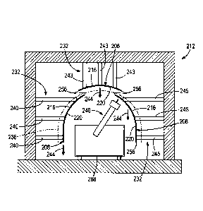
Referring now to Figs. 4-8, one example of the present disclosure relates to
an
apparatus 212 for manipulating the plurality of curved sheets 208. Each of the
plurality of curved sheets 208 includes an upper surface 216 and a lower
surface 220.
In one example, an upper surface 216 is a surface that is to be directly
impinged by
virtual vertical vectors 224 (see Fig. 6) originating from above the curved
sheet 208
and directed downward, and a lower surface 220 is a surface that is to be
directly
impinged by virtual vertical vectors 228 (see Fig. 6) originating from below
the curved
sheet 208 and directed upward. The apparatus 212 also includes tooling 232 to
be
coupled to the upper surface 216 of each of the plurality of curved sheets
208. The
tooling 232 is capable of moving the plurality of curved sheets 208 relative
to each
other and abutting the plurality of curved sheets 208 so that the upper
surface 216 of
each of the plurality of curved sheets 208 is coextensive with a virtual
arcuate surface
236 (see Figs. 6 and 7). The apparatus 212 may manipulate any number of curved
sheets 208. In one example illustrated in Figs. 5-7, the apparatus 212
manipulates
three curved sheets 208. In another example illustrated in Fig. 8, the
apparatus 212
manipulates four curved sheets 208. No matter the number of curved sheets 208,
the
tooling 232 of the apparatus 212 is capable of moving the plurality of curved
sheets
208 relative to each other and abutting the plurality of curved sheets 208 so
that the
upper surface 216 of each of the plurality of curved sheets 208 is coextensive
with a
virtual arcuate surface 236 (see Fig. 5).
CA 3054048 2019-08-30
Referring, for example, to Fig. 5, the virtual arcuate surface 236 includes no
inflection points along a cross-section thereof perpendicular to a virtual
straight line
coextensive with the virtual arcuate surface 236. As used herein, an
inflection point is
a location along a contour where a curvature of the contour changes from
concave to
convex or vice versa.
With continued reference to Figs. 6 and 7, in one example, the plurality of
curved sheets 208, abutted so that the upper surface 216 of each of the
plurality of
curved sheets 208 is coextensive with the virtual arcuate surface 236 (see
Fig. 5),
subtend a central angle between about 2 degrees and about 270 degrees in a
virtual
plane perpendicular to a virtual straight line coextensive with the virtual
arcuate
surface 236. In one example, the plurality of curved sheets 208, abutted so
that the
upper surface 216 of each of the plurality of curved sheets 208 is coextensive
with the
virtual arcuate surface 236, subtend a central angle of about 180 degrees in a
virtual
plane perpendicular to a virtual straight line coextensive with the virtual
arcuate
surface 236. The virtual arcuate surface 236, in some example, may form part
or all of
a circle, while in other examples, the virtual arcuate surface 236 may
approximate a
shape of a circle, and in still other examples, the virtual arcuate surface
236 may form
part or all of any arcuate shape. Thus, the curved sheets 208 may subtend a
central
angle associated with a circle, an approximation of a circle, or any other
arcuate
shape.
Referring to Figs. 4-8, in one example, the tooling 232 includes at least one
holder 240, 243, 245 to be removably coupled to the upper surface 216 of at
least one
of the plurality of curved sheets 208. The tooling 232 may be removably
coupled to at
least one of the plurality of curved sheets 208 in a variety of ways and all
of such
possibilities are intended to be within the spirit and scope of the present
disclosure. In
one example, the tooling 232 may include one or more suction cups 241 in
communication with a vacuum source 242. The vacuum source 242 provides
sufficient vacuum pressure to the one or more suction cups 241 to secure the
at least
one of the plurality of curved sheets 208 to the tooling 232. The vacuum
source 242
11
CA 3054048 2019-08-30
may be selectively activated and deactivated to respectively supply and
interrupt
vacuum pressure to the suction cups 241, thereby selectively coupling and
uncoupling
the tooling 232 to the at least one of the plurality of curved sheets 208. In
one
example, the at least one holder 243 may extend in a non-perpendicular
direction
relative to weight vectors 244 (see Fig. 5) of the plurality of curved sheets
208. In one
example, the at least one holder 243 may extend in a substantially parallel
direction
relative to weight vectors 244 of the plurality of curved sheets 208. In one
example,
the at least one holder 240 may extend in a substantially perpendicular
direction
relative to weight vectors 244 of the plurality of curved sheets 208. The at
least one
holder 240 has a selectively variable length.
With continued reference to Figs. 4-8, in one example, the tooling 232
includes
at least one first holder 240 and at least one second holder 243. The at least
one first
holder 240 and the at least one second holder 243 extend in different
directions. In
one example, tooling 232 also includes at least one third holder 245. In one
aspect,
.. the third holder 245 may extend in a similar direction to one of the first
holder 240 and
the third holder 243. In another aspect, the third holder 245 may extend in a
different
direction than the first holder 240 and the second holder 243. The tooling 232
is
reconfigurable. Reconfigurable tooling 232 is adjustable to accommodate sheets
208
of varying shapes, sizes, and configurations, as opposed to hard tooling,
which has a
fixed shape (i.e., not adjustable) and is configured to accommodate only a
single
shape or configuration of sheets.
Continuing to refer to Figs. 4-8, in one example, the apparatus 212 also
includes a processing station 248 facing the lower surfaces 220 of the
plurality of
curved sheets 208. In one aspect, the processing station 248 includes a
subtractive-
manufacturing apparatus 249. The subtractive-manufacturing apparatus 249 may
include a drilling apparatus 250. In another aspect, the processing station
248
includes a laser-welding apparatus 251.
12
CA 3054048 2019-08-30
With reference to Figs. 4-8, in one example, the apparatus 212 also includes a
carriage 288 configured to move relative to the plurality of curved sheets 208
and the
processing station 248 is coupled to and moveable with the carriage 288. The
processing station 248 may include a friction-stir-welding apparatus 247. One
example of a friction-stir welding apparatus 247 is illustrated in Fig. 17.
With continued reference to Fig. 4 and additional reference to Figs. 9-11, the
apparatus 212 also includes a first magnetic member 252 to be associated with
the
upper surface 216 of a first curved sheet 208 adjacent an edge 256 of the
first curved
sheet 208, a second magnetic member 260 to be associated with the lower
surface
220 of the first curved sheet 208 adjacent the edge 256 of the first curved
sheet 208, a
third magnetic member 264 to be associated with the upper surface 216 of a
second
curved sheet 208 adjacent an edge 256 of the second curved sheet 208, and a
fourth
magnetic member 268 to be associated with the lower surface 220 of the second
curved sheet 208 adjacent the edge 256 of the second curved sheet 208. The
first
magnetic member 252 is to be magnetically coupled to the second magnetic
member
260 and the third magnetic member 264 is to be magnetically coupled to the
fourth
magnetic member 268 with the edge 256 of the first curved sheet 208 and the
edge
256 of the second curved sheet 208 abutting each other.
Referring now to Figs. 4, 12 and 13, in one example, the apparatus 212 also
includes a flexible joining member 272 to be installed between the first
magnetic
member 252 and the third magnetic member 264 or between the second magnetic
member 260 and the fourth magnetic member 268 to provide a coupling between
the
first curved sheet 208 and the second curved sheet 208 with the edge 256 of
the first
curved sheet 208 and the edge 256 of the second curved sheet 208 abutting each
other. In the illustrated example, the flexible joining member 272 is
installed between
the first magnetic member 252 and the third magnetic member 264.
With reference to Figs. 4 and 12-14, in one example, the apparatus 212 also
includes a decoupling member 276 (see Fig. 14) rotatably attached to the
friction-stir-
13
CA 3054048 2019-08-30
welding apparatus 247 to eliminate the coupling provided by the flexible
joining
member 272 between the first curved sheet 208 and the second curved sheet 208.
The decoupling member 276 decouples the flexible joining member 272 from the
first
curved sheet 208 and the second curved sheet 208 while the first curved sheet
208
and the second curved sheet 208 are welded together by the friction-stir-
welding
apparatus 247. The decoupling member 276 may also translate but does not
rotate
relative to the first curved sheet 208 and the second curved sheet 208. The
decoupling member 276 may be at least partially positioned in a space 280
between
the first magnetic member 252 and the third magnetic member 264 and may move
along the space 280. The decoupling member 276 is at least partially retained
in the
space 280 by the first magnetic member 252 and the third magnetic member 264
and
may slidably engage at least one of the first magnetic member 252 and the
third
magnetic member 264. In one aspect, the decoupling member 276 slidably engages
both the first magnetic member 252 and the third magnetic member 264. In one
example, the friction-stir-welding apparatus 247 is also at least partially
positioned in
the space 280. A ball bearing or other device may be coupled between the
decoupling member 276 and the friction-stir welding apparatus 247 to allow the
friction-stir welding apparatus 247 to rotate relative to the decoupling
member 276.
The decoupling member 276 is guided along the space 280 by slidably engaging
edges of the first magnetic member 252 and the third magnetic member 264.
Referring to Figs. 4, 10 and 12, in one example, the apparatus 212 also
includes a rigid joining member 284 coupled to the first curved sheet 208 and
to the
second curved sheet 208 with the edge 256 of the first curved sheet 208 and
the edge
256 of the second curved sheet 208 abutting each other. In one aspect, the
rigid
joining member 284 includes a curvature 286.
With reference to Figs. 4-9, 12 and 13, in one example, the apparatus 212 also
includes the carriage 288 configured to move relative to the first curved
sheet 208 and
the second curved sheet 208. The friction-stir-welding apparatus 247 is
coupled to
and moveable with the carriage 288. Additionally, the second magnetic member
260
14
CA 3054048 2019-08-30
and the fourth magnetic member 268 are coupled to and are moveable with the
carriage 288. Conversely, the first magnetic member 252 and third magnetic
member
264 remain stationary relative to the plurality of curved sheets 208.
Referring now to Figs. 4-13 and 15, in one example of the present disclosure,
the apparatus 212 is configured to constrain the edge 256 of the first curved
sheet 208
and the edge 256 of the second curved sheet 208. As described above, the
apparatus 212 includes the first magnetic member 252 associated with the upper
surface 216 of the first curved sheet 208, the second magnetic member 260
associated with the lower surface 220 of the first curved sheet 208, the third
magnetic
member 264 associated with the upper surface 216 of the second curved sheet
208,
and the fourth magnetic member 268 associated with the lower surface 220 of
the
second curved sheet 208. The first magnetic member 252 is magnetically coupled
to
the second magnetic member 260 and the third magnet member 264 is magnetically
coupled to the fourth magnetic member 268 with the edge 256 of the first
curved sheet
208 and the edge 256 of the second curved sheet 208 abutting each other.
With continued reference to Figs. 4-13 and 15, in one example, the first
magnetic member 252 and the second magnetic member 260 conform to the first
curved sheet 208, and the third magnetic member 264 and the fourth magnetic
member 268 conform to the second curved sheet 208. The first curved sheet 208
and
the second curved sheet 208 may have a wide variety of shapes including, but
not
limited to, curved, flat, a combination of curved and flat, or any of a wide
variety of
shapes. Thus, the first magnetic member 252 and the second magnetic member 260
may be configured to conform to any shape of the first curved sheet 208, and
the third
magnetic member 264 and the fourth magnetic member 268 may be configured to
conform to any shape of the second curved sheet 208. In one aspect, at least
two of
the first magnetic member 252, the second magnetic member 260, the third
magnetic
member 264, and the fourth magnetic member 268 have a compliant shape. In one
aspect, the first curved sheet 208 and the second curved sheet 208 are curved
metallic sheets 208. In such an aspect, the at least two of the first magnetic
member
CA 3054048 2019-08-30
252, the second magnetic member 260, the third magnetic member 264, and the
fourth magnetic member 268 (e.g., the first magnetic member 252 and the third
magnetic member 264) are compliant to the shapes of the curved metallic sheets
208.
With continued reference to Figs. 4-13 and 15, in one example, the first
magnetic member 252 and the second magnetic member 260 are located adjacent
the
edge 256 of the first curved sheet 208, and the third magnetic member 264 and
the
fourth magnetic member 268 are located adjacent the edge 256 of the second
curved
sheet 208. In one aspect, the first magnetic member 252, the second magnetic
member 260, the third magnetic member 264, and the fourth magnetic member 268
comprise permanent magnets. In another aspect, one of the first magnetic
member
252 and the second magnetic member 260 comprises a permanent magnet and
another of the first magnetic member 252 and the second magnetic member 260
comprises a ferromagnetic material, and one of the third magnetic member 264
and
the fourth magnetic member 268 comprises a permanent magnet and another of the
third magnetic member 264 and the fourth magnetic member 268 comprises a
ferromagnetic material. In another aspect, at least one of the first magnetic
member
252 and the second magnetic member 260 comprises an electro-magnet, and at
least
one of the third magnetic member 264 and the fourth magnetic member 268
comprises an electro-magnet. In one aspect, the at least one electro-magnet is
selectively activated and deactivated. In another aspect, the second magnetic
member 260 and the fourth magnetic member 268 are electro-magnets and the
first
magnetic member 252 and the third magnetic member 264 are one of an electro-
magnet, a permanent magnet, or at least partially comprised of a ferromagnetic
material.
Referring now to Figs. 4 and 12-15, in one example, the apparatus 212 also
includes a joining member to be coupled to the first curved sheet 208 and the
second
curved sheet 208. In one example, the joining member is the flexible joining
member
272 installed between one of the first magnetic member 252 and the third
magnetic
member 264 or the second magnetic member 260 and the fourth magnetic member
16
CA 3054048 2019-08-30
268 to provide a coupling between the first curved sheet 208 and the second
curved
sheet 208 with the edge 256 of the first curved sheet 208 and the edge 256 of
the
second curved sheet 208 abutting each other. In one aspect, the flexible
joining
member 272 is installed between the first magnetic member 252 and the third
magnetic member 264. In another aspect, the flexible joining member 272 is
installed
between the second magnetic member 260 and the fourth magnetic member 268.
With continued reference to Figs. 4 and 12-15, in one example, the flexible
joining member 272 includes adhesive 292 on at least a portion thereof, and
the
flexible joining member 272 is coupled to the first curved sheet 208 and the
second
curved sheet 208 with the adhesive 292. The adhesive 292 is located on the
joining
member 272 adjacent a first edge 296 (see Fig. 12) and a second edge 300 (see
Fig.
12) of the joining member 272. The first edge 296 and the second edge 300 of
the
flexible joining member 272 oppose one another, with the first edge 296
adhesively
coupled to the first curved sheet 208 and the second edge 300 adhesively
coupled to
the second curved sheet 208. In one example, the flexible joining member 272
includes a portion 304 lacking adhesive. The portion 304 lacking adhesive is
between
the first edge 296 and the second edge 300 of the flexible joining member 272
and
may at least partially overlap the edge 256 of the first curved sheet 208 and
the edge
256 of the second curved sheet 208, with the edge 256 of the first curved
sheet 208
and the edge 256 of the second curved sheet 208 abutting each other.
With reference to Figs. 10, 12 and 15, in one example, the joining member is a
rigid joining member 284 and may be coupled to the first curved sheet 208 and
the
second curved sheet 208. The rigid joining member 284 may be coupled to the
first
curved sheet 208 and the second curved sheet 208 in a variety of ways, all of
which
are intended to be within the spirit and scope of the present disclosure. For
example,
the rigid joining member 284 may be coupled to the first curved sheet 208 and
the
second curved sheet 208 by at least one of fastening and welding. In one
aspect, the
rigid joining member 284 is coupled to the upper surface 216 of the first
curved sheet
208 and the upper surface 216 of the second curved sheet 208. In another
aspect,
17
CA 3054048 2019-08-30
the rigid joining member 284 is coupled to the lower surface 220 of the first
curved
sheet 208 and the lower surface 220 of the second curved sheet 208. The rigid
joining member 284 may include a slot 308 (see Figs. 10 and 13) and may
include a
curvature 286.
Referring to Figs. 4, 10 and 12-15, in one example, the apparatus 212 includes
a first joining member and a second joining member. The first joining member
and the
second joining member are configured to be coupled to the first curved sheet
208 and
the second curved sheet 208, with the edge 256 of the first curved sheet 208
and the
edge 256 of the second curved sheet 208 abutting each other. In one example,
the
first joining member is the rigid joining member 284 and the second joining
member is
the flexible joining member 272.
With reference to Figs. 4-13 and 15, in one example, the space 280 may be
provided between the first magnetic member 252 and the third magnetic member
264,
and the apparatus 212 includes the joining member (one or both joining members
272
and 284) coupled to the first curved sheet 208 and the second curved sheet 208
and
extending at least partially across the space 280 between the first magnetic
member
252 and the third magnetic member 264. In one example, the apparatus 212 also
includes the carriage 288 configured to move relative to the first curved
sheet 208 and
the second curved sheet 208. The second magnetic member 260 and the fourth
magnetic member 268 are coupled to the carriage 288. The second magnetic
member 260 and the fourth magnetic member 268 are configured to move with the
carriage 288 relative to the first curved sheet 208 and the second curved
sheet 208,
and the first magnetic member 252 and the third magnetic member 264 remain
stationary relative to the first curved sheet 208 and the second curved sheet
208.
Referring to Figs. 13 and 15, in one example, the apparatus 212 also includes
at least one friction-reducing member 312. At least a portion of the at least
one
friction-reducing member 312 is between at least one of the second magnetic
member
260 and the fourth magnetic member 268 and at least one of the first curved
sheet
18
CA 3054048 2019-08-30
208 and the second curved sheet 208. In one aspect, the friction-reducing
member
312 is a wheel 313. A spacing 314 between a portion of the at least one of the
second magnetic member 260 and the fourth magnetic member 268 and the at least
one of the first curved sheet 208 and the second curved sheet 208 is
maintained with
the friction reducing member 312 engaging at least one of the first curved
sheet 208
and the second curved sheet 208. In another aspect, the friction-reducing
member
312 is a layer 315 of material (e.g., hard plastic) applied to a surface of
one of the
second magnetic member 260 and the fourth magnetic member 268. In one example,
the apparatus 212 may include a plurality of friction-reducing members 312.
One of
the plurality of friction reducing members 312 may be between the second
magnetic
member 260 and the first curved sheet 208 and another one of the plurality of
friction-
reducing members 312 may be between the fourth magnetic member 268 and the
second curved sheet 208. The apparatus 212 may include any number of friction-
reducing members 312 and any number of friction-reducing members 312 may be
between one of the magnetic members and one of the curved sheets 208.
With reference to Figs. 4, 9-13 and 15, in one example, the first magnetic
member 252 includes a substrate 316 configured to engage the upper surface 216
of
the first curved sheet 208 and the third magnetic member 264 includes a
substrate
320 (see Fig. 10 configUred to engage the upper surface 216 of the second
curved
sheet 208. The substrate 316 of the first magnetic member 252 is configured to
conform to the first curved sheet 208 and the substrate 320 of the third
magnetic
member 264 is configured to conform to the second curved sheet 208. The
substrate
316 of the first magnetic member 252 and the substrate 320 of the third
magnetic
member 264 are flexible. The substrates 316 and 320 of the first magnetic
member
252 and the third magnetic member 264, respectively, may be comprised of a
variety
of elements and/or materials and all of such elements and/or materials are
intended to
be within the spirit and scope of the present disclosure. For example, the
substrates
316, 320 may be comprised of spring steel, plastic, rubber, metal, netting,
mesh, etc.
The substrates 316, 320 may also include one or more grooves 324 (see Fig. 15)
defined in a surface thereof. The grooves 324 may be defined in the surface of
the
19
CA 3054048 2019-08-30
substrates 316, 320 that engages the curved sheet 208. The grooves 324 may
assist
the substrates 316, 320 in conforming to the curved sheets 208 with which the
substrates 316, 320 engages. The grooves 324 may be defined in the surface of
the
substrates 316, 320 in any orientation such as, for example, longitudinal,
transverse to
a longitudinal extent of the substrates 316, 320, diagonal, perpendicular to
the
longitudinal extent of the substrates 316, 320, etc. or a combination thereof.
The
grooves 324 may also have any of a wide variety of cross-sectional shapes
taken
along a plane perpendicular to a longitudinal extent of the grooves 324. For
example,
cross-sections of the grooves 324 may be, but not limited to, triangular,
square,
rectangular, polygonal, semi-circular, any arcuately perimetered shape, or any
shape
having a perimeter comprised of a combination of arcs and straight lines.
Referring to Figs. 4, 9-13 and 15, in one example, the first magnetic member
252 includes a plurality of magnetic tiles 328 coupled to the substrate 316 of
the first
magnetic member 252, and the third magnetic member 264 includes a plurality of
magnetic tiles 328 coupled to the substrate 320 of the third magnetic member
264.
The plurality of magnetic tiles 328 coupled to the substrate 316 of the first
magnetic
member 252 are spaced apart from one another, and the plurality of magnetic
tiles
328 coupled to the substrate 320 of the third magnetic member 264 are spaced
apart
from one another. The magnetic tiles 328 may be comprised of permanent
magnets,
electromagnets, ferromagnetic material, or any other material have magnetic
selectively magnetic characteristics. Moreover, any number of magnetic tiles
328,
including one, may be coupled to each of the substrates 316 and 320 of the
first
magnetic member 252 and the third magnetic member 264, respectively. In the
illustrated example, the magnetic tiles 328 are substantially square in shape.
However, the magnetic tiles 328 may have any shape including, but not limited
to,
rectangular, circular, ovular, triangular, polygonal, or any shape having an
arcuate
perimeter, a perimeter comprised of straight lines, or a perimeter comprised
of both
arcs and straight lines. The magnetic tiles 328 may also be coupled to the
substrates
316 and 320 of the first magnetic member 252 and the third magnetic member 264
in
a variety of ways including, but not limited to, bonding, fastening, fusing,
unitary
CA 3054048 2019-08-30
forming (as one-piece), or in any other manners. The magnetic tiles 328 may
also be
spaced apart from one another at any distance. In one example, the magnetic
tiles
328 are spaced-apart by about 0.02 inches (0.508mm). In another example, the
magnetic tiles 328 are spaced-apart by less than 0.25 inches (6.35mm). In a
further
example, the magnetic tiles 328 are spaced-apart by less than 1 inch (25.4mm).
In
still another example, the magnetic tiles 328 are spaced-apart by less than 10
inches
(254mm). The magnetic tiles 328 may also have a variety of sizes (e.g., height
and
length). In one example, the height of one of the tiles 328 may be about 0.75
inches
(19.05mm) and the length of one of the tiles 328 may be about 0.05 inches
(1.27mm).
In another example, the height of one of the tiles 328 is less than 5 inches
(127mm)
and the length of one of the tiles 328 is less than 5 inches (127mm). In a
further
example, the height of one of the tiles 328 is less than 12 inches (304.8mm)
and the
length of one of the tiles 328 is less than 12 inches (304.8mm). The
substrates 316,
320 of the first magnetic member 252 and the third magnetic member 264 may
have a
variety of different thicknesses, any possibility of which is intended to be
within the
spirit and scope of the present disclosure. In one example, the thickness of
the
substrates 316, 320 is about 0.01 inches (0.254mm). In another example, the
thickness of the substrates 316, 320 is less than 1 inch (25.4mm). In a
further
example, the thickness of the substrates 316, 320 is less than 5 inches
(127mm).
With reference to Figs. 3 and 16, one example of the present disclosure
relates
to the vehicle 200, which includes the substructure 206 and a weldment 332
coupled
to the substructure 206. The weldment 332 includes the first sheet 208, the
second
sheet 208, and a butt weld 336 (see Fig. 16) between the first sheet 208 and
the
second sheet 208. The butt weld 336 is formed before the weldment 332 is
coupled
to the substructure 206. In one aspect, the vehicle 200 is an airplane 200. In
one
aspect, the substructure 206 is at least a portion of the frame 204 of the
airplane 200.
In one aspect, the first sheet 208 is a first metallic fuselage sheet 208 and
the second
sheet 208 is a second metallic fuselage sheet 208. In one aspect, the first
sheet 208
is one of a first metallic fuselage sheet 208, a first metallic wing sheet
208, and a first
metallic stabilizer sheet 208, and the second sheet 208 is a second metallic
fuselage
21
CA 3054048 2019-08-30
sheet 208, a second metallic wing sheet 208, and a second metallic stabilizer
sheet
208.
In Figs. 4, 15 and 16, lines connecting various elements and/or components of
the vehicle 200 or the apparatus 212 may represent mechanical, electrical,
fluid,
.. optical, electromagnetic and other couplings and/or combinations thereof.
Couplings
other than those depicted in Fig. 3 may also exist. Dashed lines connecting
the
various elements and/or components of the vehicle 200 or the apparatus 212 may
represent couplings similar in function and purpose to those represented by
solid
lines; however, couplings represented by the dashed lines are either
selectively
provided or relate to alternative or optional aspects of the disclosure.
Likewise,
elements and/or components of the vehicle 200 or the apparatus 212 represented
in
dashed lines represent alternative or optional aspects of the disclosure.
Moreover, the
absence of lines between various elements and/or components of the vehicle 200
or
the apparatus 212 does not imply an absence of a relationship, an association,
or a
coupling between the elements and/or components of the vehicle 200 or the
apparatus 212. Rather, a relationship, an association, and/or a coupling may
be
present between any of the elements and/or components of the vehicle 200 or
the
apparatus 212.
The following description pertains to examples of methods and processes
associated with the examples of vehicle and/or apparatuses described and
illustrated
in the figures. While particular steps and functionality are described herein,
such steps
and functionality are merely examples and are not intended to be limiting.
Rather, the
vehicle and/or apparatuses are intended to include more, fewer, and different
steps
and functionality, and all of such possibilities are intended to be within the
spirit and
scope of the present disclosure.
An example of the present disclosure relates to a method of manufacturing an
assembly including the first curved sheet 208 and the second curved sheet 208.
In an
example of the method, the first curved sheet 208 includes a first upper
surface 216
22
CA 3054048 2019-08-30
and a first edge 256, and the second curved sheet 208 includes a second upper
surface 216 and a second edge 256. The method includes supporting the first
upper
surface 216 and the second upper surface 216 (see Fig. 5), abutting the first
edge 256
and the second edge 256 so that the first upper surface 216 and the second
upper
surface 216 are coextensive with a virtual arcuate surface 236 (see Fig. 6),
and
welding the first edge 256 and the second edge 256 together to create a
weldment
332 after abutting the first edge 256 and the second edge 256 (see Fig. 6). In
one
aspect, the virtual arcuate surface 236 includes no inflection points along a
cross-
section thereof perpendicular to a virtual straight line coextensive with the
virtual
arcuate surface 236 (see Figs. 6 and 7). In one example, the method also
includes
constraining the first edge 256 and the second edge 256 subsequent to abutting
the
first edge 256 and the second edge 256 and prior to welding (see Figs. 6 and 9-
13).
In variant example, the method also includes reconfiguring tooling 232
supporting the first upper surface 216 and the second upper surface 216.
In one aspect, the method also includes positioning a processing station 248
to
face a first lower surface 220 of the first curved sheet 208 and a second
lower surface
220 of the second curved sheet 208 (see Figs. 5-9 and 12). In one variant, the
method also includes moving the processing station 248 relative to the first
curved
sheet 208 and the second curved sheet 208. In one example of the method,
positioning the processing station 248 also includes positioning a friction-
stir-welding
apparatus 247 to face the first lower surface 220 and the second lower surface
220.
In one example, the method also includes locating the first magnetic member
252
relative to the first upper surface 216 adjacent the first edge 256, locating
the second
magnetic member 260 relative to the first lower surface 220 adjacent the first
edge
256, locating the third magnetic member 264 relative to the second upper
surface 216
adjacent the second edge 256, locating the fourth magnetic member 268 relative
to
the second lower surface 220 adjacent the second edge 256, and magnetically
coupling the first magnetic member 252 to the second magnetic member 260 and
the
third magnetic member 264 to the fourth magnetic member 268 after abutting the
first
23
CA 3054048 2019-08-30
edge 256 and the second edge 256 (see Figs. 6, 7 and 9-13). In one example,
the
method also includes coupling a flexible joining member 272 to the first
curved sheet
208 and to the second curved sheet 208 between at least one of the first
magnetic
member 252 and the third magnetic member 264 or the second magnetic member 260
and the fourth magnetic member 268 after abutting the first edge 256 and the
second
edge 256 (see Figs. 12-14). In one example of the method, the flexible joining
member 272 is coupled to the first curved sheet 208 and the second curved
sheet 208
between the first magnetic member 252 and the third magnetic member 264 (see
Figs. 12-14). In one variant, the method also includes decoupling the flexible
joining
member 272 from the first curved sheet 208 and the second curved sheet 208
(see
Figs. 13 and 14). In one example of the method, decoupling also includes
decoupling
the flexible joining member 272 from the first curved sheet 208 and the second
curved
sheet 208 while welding the first edge 256 and the second edge 256 (see Fig.
14). In
one aspect, the method also includes rotatably coupling a decoupling member
276 to
the friction-stir-welding apparatus 247 (see Fig. 14). In one variant, the
method also
includes coupling a rigid joining member 284 to the first curved sheet 208 and
the
second curved sheet 208 after abutting the first edge 256 and the second edge
256
(see Figs. 10 and 13). In one aspect, the rigid joining member 284 includes a
curvature 286. In one example, the method also includes moving the friction-
stir-
welding apparatus 247 relative to the first curved sheet 208 and the second
curved
sheet 208. In one variant, the method also includes moving the second magnetic
member 260 and fourth magnetic member 268 relative to the first curved sheet
208
and the second curved sheet 208.
In one example, the method also includes locating the first magnetic member
252 relative to at least one of the first upper surface 216 and the second
upper
surface 216 adjacent at least one of the first edge 256 and the second edge
256,
locating the second magnetic member 260 relative to at least one of a first
lower
surface 220 of the first curved sheet 208 and a second lower surface 220 of
the
second curved sheet 208 adjacent at least one of the first edge 256 and the
second
edge 256, and magnetically coupling the first magnetic member 252 to the
second
24
CA 3054048 2019-08-30
magnetic member 260 (see Figs. 9-13). In one variant, the method also includes
locating the first magnetic member 252 and the second magnetic member 260
relative
to a same one of the first curved sheet 208 and the second curved sheet 208
(see
Figs. 9-13).
In one aspect, the method also includes providing a space between the first
edge 256 and the second edge 256 (see Figs. 5 and 8) and processing at least
one of
the first edge 256 and the second edge 256 (see Fig. 5). The space is
sufficient to
process at least one of the first edge 256 and the second edge 256. In one
example
of the method, abutting the first edge 256 and the second edge 256 occurs
subsequent to processing at least one of the first edge 256 and the second
edge 256
(see Fig. 6).
In one variant of the method, supporting the first upper surface 216 and the
second upper surface 216 further includes coupling tooling 232 to the first
upper
surface 216 and the second upper surface 216 (see Figs. 5-8). In one aspect,
the
method also includes moving the first curved sheet 208 and the second curved
sheet
208 relative to each other with the tooling 232 (see Figs. 5 and 6). In one
example of
the method, abutting also includes abutting the first edge 256 and the second
edge
256 with the tooling 232 (see Fig. 6).
In one aspect, the method also includes coupling the weldment 332 to a
structure 206 (see Figs. 3 and 16). In one example, the structure 206 is at
least a
portion of the frame 204 of an aircraft 200 (see Figs. 3 and 16).
In one variant, the method also includes processing the weldment 332 (see Fig.
7). In one aspect of the method, processing the weldment 332 includes
performing
gauge reduction on at least a portion of the weldment 332. In another example
of the
method, processing the weldment 332 includes reducing the thickness of at
least a
portion of the weldment 332. In another aspect of the method, processing the
weldment 332 includes trimming at least a portion of the weldment 332.
CA 3054048 2019-08-30
As realized herein, a variety of different aspects, examples, and variants of
the apparatus and methods are disclosed herein that include a variety of
components, features, and functionality. It should be understood that the
various
aspects, examples, and variants of the apparatus and methods disclosed herein
are
capable of including any of the components, features, and functionality of any
of the
other aspects, examples, and alternatives of the apparatus and methods
disclosed
herein in any combination, and all of such possibilities are intended to be
within the
spirit and scope of the present disclosure. The terms "aspect", "example" and
"variant" hereinabove are used interchangeably.
Many modifications and other examples of the disclosure set forth herein will
come to mind to one skilled in the art to which the disclosure pertains having
the
benefit of the teachings presented in the foregoing descriptions and the
associated
drawings.
Therefore, it is to be understood that the disclosure is not to be limited to
the
specific embodiments disclosed and that modifications and other embodiments
are
intended to be included within the scope of the teachings herein. Moreover,
although the foregoing descriptions and the associated drawings describe
example
embodiments in the context of certain illustrative combinations of elements
and/or
functions, it should be appreciated that different combinations of elements
and/or
.. functions may be provided by alternative implementations without departing
from the
scope of the teachings herein.
The Abstract of the disclosure is provided to allow the reader to quickly
ascertain the nature of the technical disclosure.
It is submitted with the
understanding that it will not be used to interpret or limit the scope or
meaning of the
teachings herein. In addition, in the foregoing Detailed Description, it can
be seen
26
Date Recue/Date Received 2021-02-09
that various features are grouped together in various embodiments for the
purpose of streamlining the disclosure. This method of disclosure is not to be
interpreted as reflecting an intention that the certain embodiments require
more
features than are expressly described.
27
Date Recue/Date Received 2021-02-09