Note: Descriptions are shown in the official language in which they were submitted.
CA 03054057 2019-08-19
WO 2018/156574 PCT/US2018/018943
VASCULAR IMPLANT
CROSS REFERENCE TO RELATED APPLICATIONS
[0001] The present application claims priority to U.S. Provisional
Application No. 62/461,616 filed February 21, 2017, the disclosure of which is
incorporated herein by reference. The provisional application is incorporated
by
reference in its entirety.
BACKGROUND
[0002] Stents for transluminal implantation are generally made of
metallic supports that are inserted into a part of the human body such as
inside a
blood vessel. Stents are usually generally cylindrical and are constructed and
arranged to expand radially once in position within the body. Some stents
include a
graft or mesh structure that can be used to minimize or eliminate the risk of
disease
herniating through a body-implanted stent during a healing phase.
[0003] The mesh structure of a stent assembly can add to the overall
width of the stent, which can be undesirable. It is therefore desirable to
manufacture
a stent such that the mechanical attachment between the mesh structure and
stent
structure is efficient from a size standpoint. It also is important that the
mesh
structure be properly and securely attached to the support portion of the
stent.
SUMMARY
[0004] Disclosed herein are methods and devices related to the use
and
construction of a vascular stent assembly. A stent assembly includes a mesh
structure that is positioned over and/or at least partially attached to a
stent structure.
Also disclosed are devices and methods for securely attaching the mesh
structure to
the stent structure. The stent assembly can also include or be coupled with a
stent
1
CA 03054057 2019-08-19
WO 2018/156574 PCT/US2018/018943
delivery system that is configured to deliver the stent assembly into a blood
vessel of
a patient.
[0005] In one aspect, there is disclosed a stent assembly adapted to
be
implanted in a blood vessel, comprising: an inner stent structure formed of a
plurality
of interconnected struts; an outer stent structure formed of a plurality of
interconnected struts, the inner stent structure positioned within the outer
stent
structure to form a space therebetween, wherein the inner stent structure and
outer
stent structure collectively form a stent body sized and shaped to fit within
a blood
vessel; and a mesh structure positioned at least partially in the space
between the
inner stent structure and outer stent structure such that the mesh structure
is
attached to the inner stent structure and outer stent structure in a sandwich
arrangement.
[0006] In another aspect, there is disclosed a method of forming a
stent
assembly comprising: forming an inner stent structure of a plurality of
interconnected
struts; forming an outer stent structure of a plurality of interconnected
struts;
positioning the inner stent structure within the outer stent structure to form
a space
therebetween, wherein the inner stent structure and outer stent structure
collectively
form a stent body sized and shaped to fit within a blood vessel; positioning a
mesh
structure at least partially in the space between the inner stent structure
and outer
stent structure; and sandwiching the mesh structure in the space between the
inner
stent structure and outer stent structure to attached the mesh structure to
the inner
stent structure and outer stent structure.
[0007] Other features and advantages should be apparent from the
following description of various embodiments, which illustrate, by way of
example,
the principles of the disclosure.
2
CA 03054057 2019-08-19
WO 2018/156574 PCT/US2018/018943
BRIEF DESCRIPTION OF THE DRAWINGS
[0008] Figure 1 shows an example stent assembly.
[0009] Figure 2 shows a schematic representation of a hem structure
that is used to attach a mesh structure to a stent structure.
[0010] Figure 3 shows an example wherein a meltable polymer leader is
attached to a Nickel Titanium (NiTi) mesh structure.
[0011] Figure 4 shows a schematic representation of a stent assembly
that includes two stent structures including an inner stent structure and an
outer
stent structure that form a space therebetween in which the mesh structure can
be
positioned and attached.
[0012] Figure 5 shows an embodiment wherein a separate sandwiching
retainer element is attached to a stent structure.
[0013] Figure 6 shows an example of a filament being hand sewn
through the end of a mesh structure.
[0014] Figure 7 shows an enlarged view of a crown region of a stent
structure having a closed loop anchor and an open loop anchor.
[0015] Figure 8 shows an embodiment of an anchor that can be located
on a crown of the stent structure.
[0016] Figure 9 shows an example stent assembly with tear drop shaped
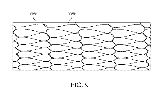
pores.
DETAILED DESCRIPTION
3
CA 03054057 2019-08-19
WO 2018/156574 PCT/US2018/018943
[0017] Disclosed herein are methods and devices related to the use
and
construction of a vascular stent. A stent assembly includes mesh structure
that is
positioned over and/or at least partially attached to a support or stent
structure. The
stent structure is formed of one or more struts that collectively form a
tubular body
sized to fit within a blood vessel. The mesh structure is formed of one or
more
filaments or sutures that are interwoven or knit to form a structure that is
coupled to
the stent structure pursuant to any of the configurations described herein.
The mesh
structure can at least partially cover or at least be partially covered by the
stent
structure.
[0018] The stent assembly can also include or be coupled with a stent
delivery system that is configured to deliver the stent assembly into a blood
vessel of
a patient. An example stent delivery system includes an elongated stent
delivery
catheter that can be inserted into a blood vessel such as in a percutaneous
manner.
The stent assembly can be mounted on the stent delivery catheter such as on a
distal region of the stent delivery catheter. The stent delivery catheter can
then be
deployed to a target site and the stent assembly can be released from the
stent
delivery catheter so that the stent assembly deploys and is retained in target
location
in the blood vessel.
[0019] The stent assembly can be used for implanting in any blood
vessel including the carotid artery. The mesh structure of the stent assembly
can be
used to minimize or eliminate the risk of disease herniating through the stent
during
a healing phase in which the stent assembly is implanted in a patient, such as
during
the first 30 days of implantation.
[0020] The stent assembly can be any stent, including a self-
expanding stent, or a stent that is radially expandable by inflating a balloon
or
expanded by an expansion member. The stent can also be made of any desired
material, including a metallic material, a metal alloy (e.g., nickel-titanium)
or even
polymeric composites. The stent can have any wire or cell design. The vessels
in
which the stent of the present invention can be deployed include but are not
limited
to natural body vessels such a blood vessel.
4
CA 03054057 2019-08-19
WO 2018/156574 PCT/US2018/018943
[0021] Various examples of mesh configurations for coupling to a
stent
structure are described herein. The mesh configurations can include, for
example,
(1) material of the mesh; (2) thread configurations of the mesh; (3) size and
quantity
of filaments that form the mesh; (4) modes of attachment between the mesh and
the
stent, etc., and combinations thereof. Various embodiments of the stent
structure for
attaching to the mesh structure are also described herein.
[0022] Figure 1 shows a perspective view of a stent assembly 100 that
includes a stent body 105 (or stent structure) that is coupled to a mesh body
110 (or
mesh structure). The stent body is a formed of a plurality of interconnected
struts or
wires that are attached to one another to form a plurality of cells or
openings. The
struts can be attached to one another in any of a variety of manners. The
stent body
generally forms a cylindrical shape that is sized and shaped to fit within a
blood
vessel, such as a carotid artery.
[0023] In an embodiment, the mesh structure (sometimes referred to as
"knit") is made of a shape memory alloy, such as Nickel Titanium (NiTi or
Nitinol). In
an example embodiment, the mesh structure formed of a 0.0005 inch nitinol
filament
positioned over the stent. In another example embodiment, the mesh structure
is
formed of a polyester monofilament or multifilament.
[0024] A stent with a Polyethylene terephthalate ("PET") mesh
structure
can be crimped down on to the stent structure for loading onto a delivery
system.
The mesh structure has a wall thickness such that it does not increase or
significantly increase the overall thickness of the entire stent assembly. In
this
regard, the mesh structure may be dimensioned such that it has a wall
thickness that
is less than double the wall thickness of the stent structure.
[0025] There are now described various structures and methods for
attaching the mesh structure to the stent structure.
Attachment via Glue
CA 03054057 2019-08-19
WO 2018/156574 PCT/US2018/018943
[0026] In an embodiment for attaching the mesh structure 110 to the
stent structure 105, a hem is formed and is used as a mechanical interface
between
the mesh structure 110 and the stent structure 105. For example, a planar
portion of
the material that is used to form the mesh structure is turned over itself to
form such
a hem. The hem defines a space in which a corresponding portion of the stent
structure 105 can be inserted and secured. Figure 2 shows a schematic
representation of the hem structure 205, which is attached to the mesh
structure 110
and to the stent structure 105.
[0027] The separate hem structure 205 is attached to the mesh
structure
110 such as via sewing or gluing. Then the mesh structure 110 is glued to the
stent
structure 105 via any of a variety of methods. For example, the mesh structure
can
be soldered to the stent structure such as by gold soldering a NiTi mesh
structure to
the stent structure. Alternatively, a polymer glue, a melt, a solvent polymer
bond,
etc. or a conformal polymer coating can be used. Figure 3 shows some examples
of
this wherein a meltable polymer leader 305 is attached to an NiTi mesh
structure
110. The attached polymer portion of the mesh structure is then melted,
bonded, or
otherwise mechanically attached to the stent structure.
[0028] In this manner, the stent assembly includes a transition from
a
shape memory material, such as Nitinol, to a polymer material at an end of the
stent
assembly.
Mechanical Attachment via Sandwiching
[0029] In another embodiment for attaching the mesh structure 110 to
the stent structure 105, the mesh structure 110 is sandwiched between an inner
stent structure 105a and an outer stent structure 105b. That is, the stent
assembly
includes two stent structures including an inner stent structure 105a and an
outer
stent structure 105b, as shown schematically in Figure 4. The stent structures
105a
and 105b form a space therebetween in which the mesh structure 110 can be at
least partially positioned. In this manner, the mesh structure 110 is
interposed or
6
CA 03054057 2019-08-19
WO 2018/156574 PCT/US2018/018943
sandwiched between the stent structures 105a and 105b to form a secure
attachment therebetween.
[0030] In an example, the following specifications can be used for
the
inner stent structure and outer stent structure:
= A .003" outer stent structure over a NiTi mesh structure and a 0.006"
inner
stent structure;
= A .002" outer stent structure over a NiTi mesh structure and a 0.008" or
0.009" inner stent structure.
[0031] As shown in Figure 5, in another sandwich embodiment, a
separate sandwiching retainer element 505 is added on crown ends of the stent
structure only. The mesh structure is not shown in Figure 5.
[0032] The sandwich embodiments are now described further. An inner
stent structure and an outer stent structure can encapsulate a mesh structure
by
placing the mesh structure therebetween. The inner stent structure exerts
higher
radial strength or radially outward force than the outer stent structure such
that a net
resulting force between the inner and outer stent structures pushes the entire
stent
assembly devices toward a blood vessel wall (e.g., radially outward) when
implanted.
Length-wise, both the inner stent structure and outer stent structure are
longer than
the length of the mesh structure. In an embodiment, both the inner stent
structure
and outer stent structure have identical specifications except two parameters.
The
first parameter is of strut length (SL) for the struts of the stent structure.
The second
parameter is a wall thickness (wt) of the stent structure.
[0033] In an example, the SL of the inner stent structure about 15%
shorter and the SL of outer stent structure is about 15% longer. That is, all
of the
strut lengths of the inner stent structure are smaller than the shortest strut
of the
outer stent structure. The net difference in SL is 30% between inner stent
structure
and outer stent structure. By having shorter SL, the radial strength becomes
higher.
7
CA 03054057 2019-08-19
WO 2018/156574 PCT/US2018/018943
By having longer SL, the radial strength becomes lower. Thus, the radial
strength of
the entire stent assembly device exerts its radial strength outward (i.e.,
toward the
blood vessel wall).
[0034] The wt of the inner stent structure is 0.006" and the wt of
outer
stent structure is 0.003". By having thinner wt, the radial strength becomes
lower. By
having thicker wt, the radial strength becomes higher. Thus, the radial
strength of the
composite device exerts its radial strength outward (e.g., toward the vessel
wall
direcion). Also the net wt of the composite device is at or below a 0.009"
threshold
wt. By having both wt and SL tailored for either higher or lower radial
strength for
both inner and outer stents, respectively, the net radial strength of the
composite
device exerts outward force toward the vessel wall.
Attachment via Machine Sewing
[0035] As mentioned, a hem can be formed on the mesh structure. The
mesh can be formed using a sewing machine and the hem is attached to the stent
structure. The mesh structure can also be machine sewed directly onto the
struts of
the stent structure. Pursuant to such a process, a filament is used to form a
stitch
pattern that attaches the mesh structure to the stent structure. The sewing
stich
pattern can be formed from any variety of filaments including, for example,
205 hand
stitch and 301 lock stitch. The stitching can be formed along struts of the
stent (or
just across struts of the stent) in a circumferential orientation. The stitch
width can be
constant or vary around the device's circumference.
[0036] The stitch can have a constant or a variable stitch length.
For
example, the stitch can be tighter at a certain number of discrete locations
along the
stent structure and less tight at remaining locations. The knit structure can
also form
pores of various shapes and sizes.
Attachment via Hand Sewing
8
CA 03054057 2019-08-19
WO 2018/156574 PCT/US2018/018943
[0037] In another embodiment, the mesh structure is attached to the
stent structure by hand sewing ends of the mesh structure to itself and/or to
the
stent. Preferred sewing patterns can be used with custom features on stent to
make
it easier to attach a suture onto the stent. Example sewing patterns include
test 301
lock stitch and 205 hand stitch.
[0038] Figure 6 shows an example of a filament 605 being hand sewn
through the end of the mesh structure 110. Individual loops of suture are then
used
to attach the mesh structure to the crowns of the stent structure. The
filament is
sewed so that it runs in and out of the loops. The quantity of loops may vary.
In an
embodiment, there are 10 to 100 loops.
[0039] In an embodiment, a filament (such as a PET filament) is sewn
through the end of a NiTi mesh structure and connected to the stent structure.
The
filament is sewn through one or more loops of the mesh structure and also
through
donut holes or apertures along the crown of the stent structure.
Attachment via Hand Sewing with Suture Anchors
[0040] A crown region of the stent assembly can include one or more
types of suture anchors. The crown of the stent includes a first type of
suture anchor
with a "split 0" configuration in which the suture anchor forms a partial loop
with a
gap or opening along its circumference. The gap or opening provides a passage
for
the suture to be inserted into the anchor.
[0041] The second type of suture anchor is a "solid circle" or closed
loop
in which the suture anchor forms a completely closed loop. Figure 7 shows an
enlarged view of the crown region of a stent structure having a closed loop
anchor
705 and an open loop anchor 710. The suture can be looped through the open
loop
anchor and secured in a cleat manner, wherein the suture also extends through
the
open loop anchor. The suture can alternately be looped around the closed loop
anchor and also be wrapped around a base of the anchor to further secure the
suture thereto.
9
CA 03054057 2019-08-19
WO 2018/156574 PCT/US2018/018943
[0042] The mesh structure is desirably secured to the stent structure
in a
manner that will secure the mesh structure to the stent structure against
forces
applied in both a distal direction and a proximal direction along a
longitudinal axis of
the stent structure. That is, the mesh structure will remain secured and not
detach
from the stent structure regardless of a direction of relative force between
the stent
structure and the mesh structure.
[0043] Figure 8 shows an embodiment of an anchor 805 that can be
located on a crown of the stent structure. The anchor forms a closed loop and
includes one or more "ears", prongs, barbs, or protrusions 810 that serve as
structure for further securing the suture to the anchor. As shown in Figure 8,
the
suture 805 can wrap through the closed loop and also around the ears to secure
the
suture thereto and prevent it from disengaging from the stent structure during
loading
and/or removal of the stent assembly from a delivery system. It should be
appreciated that the ear structures are just examples and that other
structures can
be used to further secure the suture to the stent structure.
Mechanical Attachment via Interconnecting Features
[0044] In another embodiment, the mesh mechanically interconnects
with features of the stent. Various methods can be used to mechanically attach
the
mesh structure to the stent structure. For example, the end of the mesh
structure can
be looped over the end of the stent structure or the mesh structure is looped
inside
itself with both layers of the knit on the outside of the stent. The two knit
layers can
then be bonded or sutured together with this construct.
[0045] Alternatively, the end of the knit can be "finished" so that
the
filament used for the knitting does not unwind or unknit. The end of the knit
is
secured with any of the methods described in this disclosure. Next, the ends
of the
mesh structure are looped over some features of the stent. These features may
include the crowns of the stent or finger-like protrusion structure. The
protrusions
may be directed away or outwardly to help the mesh structure to more easily
engage.
CA 03054057 2019-08-19
WO 2018/156574 PCT/US2018/018943
Attachment via Polymer Coating
[0046] In another embodiment, a polymer coating can be used to finish
the ends of the mesh structure and/or attach the mesh structure to the stent
structure. A thin layer of polymer is added on the end of the mesh structure
to
prevent the mesh structure from unraveling before attaching to the stent
structure.
[0047] Alternately, a polymer coating is used to both help "finish" the end
of the mesh structure and also act as a mechanism to attach mesh stent struts
all at
one time. For this example, the polymer can be sprayed on just the ends of the
stent
assembly thereby leaving the center of the stent/mesh structure clear of any
polymer. The polymer coating can be applied to one or more rows of knit
elements,
less than one row of knit element, one or more strut rung element, or less
than one
strut rung element. To coat just the end of the knit, it may be required to
mask the
center of the stent structure with a masking agent that can be removed after
the
coating process is complete.
[0048] The polymer coating can be achieved with a dip or spray process
with various levels of solids. Multiple passes may be required to get adequate
coating. The key will be to encapsulate the entire knit filament-stent strut
element
with the coating to ensure it is adequately attached.
[0049] A variety of polymer gluing or coating options to secure mesh end
and/or bond to stent are shown in table below.
Stent Company Polymers Reference
Cypher Cord Parylene C pruner Cypher IPU (2003)
Cord
iiiigiiiiiiiiiiiiiiiiiiiiiiiiiiiiiiiiig1111111111111111111111111111111111111111
1111111111111111111111111111m1116.14of
Taxus Boston Poly(styrene-isobutylene-styrene) Taxus Express2 IFU
(2012)
Scientific SIBS Boston Scientific
337'..s.s.s."=7:7M .7.7'.777777777377 7s."777777777777.77777:s.r.777MMUMMUM:
:7isji7M7i77i7Msj:"-'ssj:"77'7r77"777'MMMggggggi
Altdtrontom anwsphorooltdinoVeYmmwmwm EtIroTotervi0.001170337.41390mmiiiiiiii
Endeavor Metronic Blend of: J Biomed Mater Res (2008)
85A:
Resolute
Polyvinylpyrrolidone (PVP); 1064-1071
11
CA 03054057 2019-08-19
WO 2018/156574 PCT/US2018/018943
Poly(butylmethacryl ate/vinyl
acetate) (C 10);
Poly(vinyl acetate/vinylpyrroli done/
hexamethacryl ate) (C 19)
..... = = = = = = = = = = = = = = =
.=.=.=.=.=.=.=..=.=.=.=.=.=.=.=.=.=.=.=.=.=.=.---- = =
.C..60.6110iiibitiammEmommowiCth Crthovac Inter (2006)
iiiLIMMENIEbbtrmimmiNa
Other MiSC PET, Peb ax, Silicone, Urethanes,
p aryl ene m and/or C with or
without functional groups, bi omer
[0050] Other materials that can be used include, for example:
[0051] Parylene C: Conformal coating formed by vapor deposition.
Long history with medical devices.
[0052] PEVA: Rubbery copolymer. Available in broad range of vinyl
acetate ranges. Very low VA content (less than 10%) is difficult to dissolve.
Higher
VA (18-33%) would be very flexible and adhesive
[0053] PBMA: Hard, tough material. Not as flexible as PEVA. Easily
dissolvable in several solvents.
[0054] SIBS: Tough, rubbery material. Dissolvable in several solvents.
[0055] PC: Tends to form as a self-assembled monolayer.
[0056] PVP: Water soluble polymer.
[0057] Polyvinylidenefluroide/hexafluoropropylene Melt processible.
Attachment via Welding
[0058] In another embodiment, the mesh structure can also be welded to
the stent structure. For example, the following materials can be used in the
weld
process:
12
CA 03054057 2019-08-19
WO 2018/156574 PCT/US2018/018943
[0059] - Niti wire (from Knit) to Niti stent weld: Laser welding,
resistance
welding
[0060] - Polymer filament (from Knit) to Niti stent weld
[0061] Various mesh constructions can be used. A circular knitting
method can be used wherein the pore size can be formed from any one of more
polymer or metallic fiber or combinations there of. Example NiTi or PET fibers
are
about 0.001", 0.00075", 0.0005" diameter wires.
Exemplary Cell Pattern for Mesh or Stent Structure
[0062] In an embodiment shown in Figure 9, the knit or mesh structure
can be formed and/or post proccessed to form a kissing pore or cell pattern.
For
example, the mesh structure forms a plurality of tear drop shaped pores 905
with
enlarged rounded regions on a first end and smaller, pointed regions on a
second
end. In the kissing pattern, the enlarged rounded regions of at least two of
the tear
drop shaped pores are in contact or abut with one another. A tear drop shaped
pore
can extend along a long axis with the rounded region of a pore being
positioned
along the axis at a first end and the pointed region positioned along the axis
on a
second end, wherein the axis is straight. The pores can be arranged in rows
such
that the larger regions of two pores are in direct contact in "kissing"
arrangement
while the smaller regions of the two pores are spaced apart from one another.
A
series of pores (such as pores 905a and 905b) are co-axial along a common long
axis. One way this pattern can be achieved is to knit a tubular knit structure
with
individual pores wherein at least some of the pores are generally circular,
square or
rectangular in shape. The tubular knit can be stretched longitudinally onto a
smaller
diameter mandrel to yield elongated pores which exhibit the kissing or tear
drop
shaped pattern; the structure may then be optionally heat set to retain this
shape.
[0063] The above-described, tear drop shaped pore arrangement can
achieve smaller pore sizes using particular wires to form the stent assembly
and
pores, such as Nitinol wire in the 0.0005" to 0.001" diameter range. The
"kissing"
13
CA 03054057 2019-08-19
WO 2018/156574 PCT/US2018/018943
pore configuration can achieved minimum pore widths of 100-250um and a
Length:Width ratio ranging from 3:1 to 10:1 in an example embodiment.
[0064] While this specification contains many specifics, these should
not
be construed as limitations on the scope of an invention that is claimed or of
what
may be claimed, but rather as descriptions of features specific to particular
embodiments. Certain features that are described in this specification in the
context
of separate embodiments can also be implemented in combination in a single
embodiment. Conversely, various features that are described in the context of
a
single embodiment can also be implemented in multiple embodiments separately
or
in any suitable sub-combination. Moreover, although features may be described
above as acting in certain combinations and even initially claimed as such,
one or
more features from a claimed combination can in some cases be excised from the
combination, and the claimed combination may be directed to a sub-combination
or
a variation of a sub-combination. Similarly, while operations are depicted in
the
drawings in a particular order, this should not be understood as requiring
that such
operations be performed in the particular order shown or in sequential order,
or that
all illustrated operations be performed, to achieve desirable results. Only a
few
examples and implementations are disclosed. Variations, modifications and
enhancements to the described examples and implementations and other
implementations may be made based on what is disclosed.
14