Note: Descriptions are shown in the official language in which they were submitted.
SEMI-RIGID DUCT SYSTEM
This disclosure relates to the field of duct systems for carrying air streams
in mines,
tunnels, and the like and in particular a semi-rigid duct system that can be
transported
readily and assembled on site.
BACKGROUND
Air ducts are required to carry air to underground locations such as mines and
tunnels.
Such ducts are commonly made from flexible fabric which is light and can be
collapsed
for transport down into underground installation sites where space is limited.
Such fabric
ducts however have limitations when air pressures are quite high or when
dealing with
negative air pressures.
United States Patent Number 8,336,925 to Paquet et al. discloses a duct system
where
flexible panels, which can be readily moved into a confined area such as a
mine, are
formed into tubular sections with edges connected and sealed on site. The
sections are
then connected end to end with collars sealed over ends of abutting adjacent
tubular
sections.
United States Patent Number 5,472,768 to Anson discloses a tubular duct system
where
tapered flexible panels are formed into tapered tubular sections with edges
that overlap
and are fastened together. The panels have tapering edges such that when the
edges are
connected the diameter of one end is smaller than the diameter of the other
end and the
sections are joined by inserting the smaller end of one section into the
larger end of the
adjacent section in a telescoping manner. Sealing is not required in the
illustrated
application of a debris chute.
I 96994741
CA 3054121 2019-09-05
SUMMARY OF THE INVENTION
The present disclosure provides a semi-rigid duct system that overcomes
problems in the
prior art.
In a first embodiment the present disclosure provides a plurality of tubular
sections
connected together, each tubular section comprising a flexible panel having a
length
between first and second end edges thereof, a first width between first and
second side
edges at the first end edge, and second width between first and second side
edges at the
second end edge, wherein the first width is less than the second width. Inner
and outer
joiner plates are attached to inner and outer faces of the flexible panel
along the first side
edge and extend outward from the first side edge such that a recess is formed
between the
inner and outer joiner plates, and the second side edge is inserted into the
recess and
fastened in the recess to form the flexible panel into the tubular section
with the inner
joiner plate on an interior of the tubular section and the outer joiner plate
on an exterior
of the tubular section. Each tubular section has an open substantially
circular first end
with a first diameter at the first end edge of the panel and an open
substantially circular
second end with a second diameter at the second end edge of the panel, and
wherein the
first diameter is less than the second diameter. A plurality of first end
anchors are spaced
around each tubular section at a first anchor distance from the first end of
the tubular
section and a corresponding plurality of second end anchors are spaced around
each
tubular section at a second anchor distance from the second end of the tubular
section.
The first end of each tubular section is inserted into the second end of an
adjacent tubular
section such that a portion of the outer face of each tubular section
proximate to the first
end thereof bears against a portion of the inner face of the adjacent tubular
section
proximate to the second end thereof Each of a plurality of end pulling
elements is
connected between one of the first anchors on one tubular section and one of
the second
anchors on the adjacent tubular section, and each end pulling element is
operative to exert
a force drawing the connected first and second anchors together.
196994741 2
CA 3054121 2019-09-05
In a second embodiment the present disclosure provides a method of providing a
duct
system. The method comprises forming a plurality of tubular sections, each
tubular
section formed by: providing a flexible panel having a length between first
and second
end edges thereof, a first width between first and second side edges at the
first end edge,
and second width between first and second side edges at the second end edge,
wherein
the first width is less than the second width; attaching inner and outer
joiner plates to
inner and outer faces of each panel along the first side edge such that the
joiner plates
extend outward from the first side edge such that a recess is formed between
the inner
and outer joiner plates; inserting the second side into the recess and
fastening the second
side edge in the recess to form the panel into the tubular section with the
inner joiner
plate on an interior of the tubular section and the outer joiner plate on an
exterior of the
tubular section; wherein each tubular section has an open substantially
circular first end
with a first diameter at the first end edge of the panel and an open
substantially circular
second end with a second diameter at the second end edge of the panel, and
wherein the
first diameter is less than the second diameter; attaching a plurality of
first end anchors
spaced around each tubular section at a first anchor distance from the first
end of the
tubular section; attaching a corresponding plurality of second end anchors
spaced around
each tubular section at a second anchor distance from the second end of the
tubular
section; inserting the first end of each tubular section into the second end
of an adjacent
tubular section; and connecting an end pulling element between each of the
first and
second anchors and operating each end pulling element to exert a force drawing
the
connected first and second anchors together such that the first end of each
tubular section
is forced into the second end of the adjacent tubular section and such that a
portion of the
outer face of each tubular section proximate to the first end thereof bears
against a
portion of the inner face of the adjacent tubular section proximate to the
second end
thereof.
19699474v I 3
CA 3054121 2019-09-05
The duct system of the present disclosure can be transported to a confined
work site such
as a mine or like tunnel, where the tubular sections can be quickly formed and
ins,talled
by rolling the flexible panels such that the side edges can fastened together
to form the
tapered tubular sections. Then the smaller first end of one tubular section is
simply
inserted into the larger second end of the next tubular section and secured
and tightened
with the end pulling elements to form the duct system.
DESCRIPTION OF THE DRAWINGS
While the invention is claimed in the concluding portions hereof, preferred
embodiments
are provided in the accompanying detailed description which may be best
understood in
conjunction with the accompanying diagrams where like parts in each of the
several
diagrams are labeled with like numbers, and where:
Fig. 1 is a schematic cut away side view of an embodiment of the duct system
of the
present disclosure;
Fig. 2 is a schematic top view of a flexible panel of the embodiment of Fig.
1;
Fig. 3 is a schematic sectional end view of the embodiment of Fig. 1;
Fig. 4 is a schematic end view of the first and second open ends of-a tubular
section of
the embodiment of Fig. 1;
Fig. 5 is a schematic sectional view along line 4 - 4 in Fig. 4 of the
connection of one
tubular section with another tubular section of the embodiment of Fig. 1;
Fig. 6 is a schematic side view of the embodiment of Fig. 1 showing the joiner
plates
and first and second anchors aligned;
19699474v1 4
CA 3054121 2019-09-05
Fig. 7 is a schematic sectional side view of the connection of one tubular
section with
another tubular section of the embodiment of Fig. 1 showing the arrangement of
the
joiner plates and first and second ends of the tubular sections;
Fig. 8 is a schematic perspective view of a tubular section of the embodiment
of Fig. 1;
Fig. 9 is a schematic top view showing the lock tab in position to be inserted
into the
lock notch;
I0
Fig. 10 is a schematic side view of the half rings that form the reinforcing
rings;
Fig. 11 is a schematic side view of a band wrapped around the second end of
the
tubular section 3.
DETAILED DESCRIPTION OF THE ILLUSTRATED EMBODIMENTS
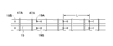
Fig. 1 schematically illustrates an embodiment of a duct system 1 of the
present
disclosure comprising a plurality of tubular sections 3 connected together.
As shown in Fig. 2, each tubular section 3 comprises a flexible panel 5 having
a length L
between first and second end edges 7A, 7B thereof, a first width W1 between
first and
second tapering side edges 9A, 9B at the first end edge 7A, and a second width
W2
between first and second side edges 9A, 9B at the second end edge 7B. The
first width
W1 is less than the second width W2 such that when the panel 5 is rolled up so
the first
and second side edges 9A, 9B are abutted, the tubular section 3 is formed with
a slightly
tapering shape so that the first end 1 IA of the tubular section 3 can be
inserted into the
second end 11B of an adjacent tubular section as illustrated in Fig. 1.
Typically the
I 9699474v I 5
CA 3054121 2019-09-05
difference between W1 and W2 will be less than one centimeter, and the
difference in the
widths WI, W2 shown in Fig. I exaggerated to illustrate the concept.
Inner and outer joiner plates 13, 15 are attached to inner and outer faces 5A,
5B of each
panel 5 along the first side edge 9A thereof, typically by rivets, adhesives,
or the like,
such that the joiner plates 13, 15 extend outward from the first side edge 9A.
The
flexible panel 5 is then rolled by raising the side edges 9A, 9B shown in Fig.
2 and
bringing them together as shown in Fig. 3 and inserting the second side edge
9B into the
recess 17 formed between the inner and outer joiner plates 13 and 15 and
fastening the
second side edge 9B in the recess 17 to form the panel 5 into the tubular
section 3. As
seen in Fig. 4 the inner joiner plate 13 is on an interior of the tubular
section 3 and the
outer joiner plate 15 is on an exterior of the tubular section 3.
Because of the tapering side edges 9A, 9B of the panel 5, each tubular section
3 has, as
shown in Fig. 4, an open substantially circular first end II A with a first
diameter DI at
the first end edge 7A of the panel 5 and an open substantially circular second
end 11B
with a second diameter D2 at the second end edge 7B of the panel 5. The first
diameter
DI is less than the second diameter D1 allowing the first end I1A of each
tubular section
3 to be inserted into the second end I IB of the adjacent tubular section 3 to
form the duct
system 1.
As shown in Fig. 5, a plurality of first end anchors I 9A are spaced around
each tubular
section 3 at a first anchor distance AD I from the first end HA of the tubular
section 3,
and a corresponding plurality of second end anchors 19B are spaced around each
tubular
section 3 at a second anchor distance AD2 from the second end 11B of the
tubular section
3. The first end 1 I A of each tubular section 3 is inserted into the second
end 11B of an
adjacent tubular section 3 such that a portion of the outer face 5B of each
tubular section
proximate to the first end 11A thereof bears against a portion of the inner
face SA of the
adjacent tubular section 3 proximate to the second end 11B thereof
19699474v1 6
CA 3054121 2019-09-05
The first end 11 A of each tubular section 3 is inserted into the second end 1
IB of the
adjacent tubular section 3 an insertion distance ID, and the first anchor
distance AD I is at
least equal to or greater the insertion distance ID so the anchors do not
interfere with the
insertion. Typically the second anchor distance AD2 is greater the insertion
distance ID
so that the second anchors can be attached with fasteners 27 that extend past
the inner
face 5A of the tubular section 3 so that the fasteners 27 do not interfere
with insertion.
An end pulling element, such as the illustrated cinch strap 25 is connected
between the
first end anchor 19A on one tubular section 3 and the second end anchor 19B on
the
adjacent tubular section 9. Pulling on the tail end 25A of the cinch strap 25
exerts a force
F drawing the connected first and second end anchors 19A, 19B together, and
when the
tail end 25A is released, tension is maintained on the cinch strap 25.
Tightening the cinch
straps 25 around the periphery of the tubular section 3 causes the first end
ii A of the
tubular section 3 to move into the second end 11B of the adjacent tubular
section 3 such
that the outer face 5B of each tubular section bears quite tightly against the
inner face 5A
of the adjacent tubular section 3 to form a substantially air tight seal. The
duct systems of
the present disclosure are sometimes subjected to significant blast forces
during mining
operations and it is contemplated that the end pulling elements could be
provided by a
resilient elastic strap which would give rather than break in response to such
blast forces.
As shown in Fig. 6, the first end 1 1 A of each tubular section is inserted
into the second
end 11B of the adjacent tubular section 3 such that the joiner plates 13, 15
and first end
anchors 19A on each tubular section 3 are substantially aligned with the
joiner plates 13,
.. 15 and second end anchors 19B on the adjacent tubular section 3. Such
configuring of
the tubular sections 3 allows the user to align the visible outer joiner
plates 15 and then
the corresponding first and second end anchors 19A, I 9B will be aligned as
well.
i 9699474v I 7
CA 3054121 2019-09-05
Each tubular section 3 is formed such that each tubular section 3 is
substantially airtight
from the first end 11A thereof to the second end thereof 11A since the fit of
the second
side edge 9B in the recess 17 between the joiner plates 13, 15 is quite tight,
and the
connection of each tubular section 3 to the adjacent tubular section 3 is
substantially
airtight since the cinch straps 25 exert sufficient force to push the outer
face 5B of each
tubular section against the inner face SA of the adjacent tubular section 3
such that little
air escapes. While not completely air tight the connections are sufficiently
air tight for
the relatively low pressure, high flow rate ducting purposes contemplated for
use with the
disclosed system 1.
As schematically illustrated in Fig. 7, the first end 11A of each tubular
section 3 is
inserted into the second end of the adjacent tubular section the insertion
distance ID. The
outer joiner plate 15 is configured to extend from a first end 15A thereof
located the
insertion distance TD from the first end 11A of the tubular section 3 to a
second end 15B
IS thereof located at the second end 11B of the tubular section 3. Thus
when assembled as
in Fig. 6, the outer joiner plates 15 do not interfere with insertion and form
a continuous
plate along the outside of the duct.
The inner joiner plates 13 are configured to extend from a first end 13A
thereof located
format or near the first end 11A of the tubular section 3 to a second end 13B
thereof
located the insertion distance ID from the second end 11B of the tubular
section 3. With
this configuration the inner joiner plate 13 does not interfere with
insertion, and the
recess 17 enclosing the second side edge 9B extends substantially the full
exposed length
of each tubular section 3 to prevent air from escaping.
As seen in Fig. 8 in each tubular section 3 the second side edge 9B is
fastened in the
corresponding recess 17 by a plurality of side pulling elements 29, each
extending over
the outer joiner plate 15 and connected to side anchors 31 attached to the
tubular section
3 on each side of the outer joiner plate 15. The side pulling elements 29 can
conveniently
19699474v1 8
CA 3054121 2019-09-05
be provided by cinch straps 25, similar to the end pulling elements, that are
operative to
exert a force drawing the second side edge 9B into the recess 17.
To facilitate guiding the second side edge 9B into the recess 17, outer joiner
plate 15
extends from the first side edge 9A of the flexible pane 5 a greater distance
than the inner
joiner plate 13, as best seen in Fig. 3, When folding the edges 9A, 9B
together the outer
joiner plate 15 will keep the second side edge 9B from springing up before it
is actually
in the recess. The inner and outer joiner plates 13, 15 adjacent to the recess
17 are also
chamfered with bevels 33 helping to guide the second side edge 9B into the
recess 17.
To further facilitate forming the flexible sheet 5 into the tubular section 3
the illustrated
system 1 also comprises a lock tab 35 extending from the second side edge 9B
of each
flexible panel 5 and a corresponding lock notch 37 defined in the first side
edge 9A of
each flexible panel 5. The lock tab 35 and lock notch 37 are configured such
that when
the second side edge 9B is inserted into the recess 17, the lock tab 35 flexes
as it enters
the lock notch 37 and locks into the lock notch 37
As seen in Fig. 9, as the lock tab 35 moves in the direction of' the arrow
into the lock
notch 37 the lock arms 39 will be flexed outward until the protrusions 41 on
the tab 35
coincide with the indents 43 of the notch 37, where the lock arms 39 will flex
back with
the protrusions 41 locked in the corresponding indents 43.
To facilitate inserting the first end 11A of a tubular section 3 into the
second end 11B of
an adjacent tubular section 3, the first end edge 7A of each flexible panel 5
comprises a
shoehorn element 45 extending from a middle portion of the first end edge 7A
as seen in
Figs. 2 and 8. The shoehorn element 45 on one tubular section can be rested
inside the
second end 11B of the adjacent tubular section to help align the ends HA, 11B
for
insertion.
I 96994741 9
CA 3054121 2019-09-05
To maintain the desired circular shape of the open ends 11 of the tubular
sections 3,, first
and second reinforcing rings 47A, 47B are spaced along and extend around each
tubular
section 3.. The illustrated reinforcing rings 47 each comprise two half rings
49A, 49B
fastened to each other with bolts 51 or the like after the second side edge 9B
is inserted
into the recess 17 to form the tubular section 3.
The reinforcing rings 47 are configured to correspond to an outside diameter
of the
tubular section 3 to substantially prevent deformation of the open ends 11 and
maintain
the circular shape to facilitate insertion. Since the tubular sections 3 are
tapered slightly,
the outside diameter will vary slightly along the length of the tubular
section 3, and the
bolts 51 can be tightened or loosened somewhat to accommodate these
variations. .
Where negative air pressures are contemplated further reinforcing rings may be
added
spaced along the length of the tubular sections 3 between the first and second
reinforcing
rings 47A, 47B.
Fig. 11 schematically illustrates a sealing band 53 wrapped around the second
end 11B of
each tubular section 3, and a band tightener 55, such as a ratchet or buckle,
operative to
exert a tightening force on the sealing band 53 to force the inner face 5A of
the second
end portion of each tubular section 3 against the outer face 5B of the first
end portion of
the adjacent inserted tubular section. Typically the sealing band 53 will be
wrapped
around the second end of the tubular section before the cinch straps 25 are
connected
between the adjacent tubular sections so the band 53 will lie flat against the
outer surface
of the tubular section 3. The sealing band 53 can be tightened after the
insertion is
complete and will act to further seal the connection of the tubular sections.
The present disclosure also provides a method of providing a duct system F.
The method
comprises forming a plurality of tubular sections 3 where each tubular section
3 is formed
by providing a flexible panel 5 having a length between first and second end
edges 7A,
1909474v I 10
CA 3054121 2019-09-05
7B thereof, a first width W1 between first and second side edges 9A, 9B at the
first end
edge 7A, and second width w2 between first and second side edges 9A, 9B at the
second
end edge 7B, wherein the first width WI is less than the second width W2,
attaching
inner and outer joiner plates 13, 15 to inner and outer faces 5A, 5B of each
panel 5 along
the first side edge 9A such that the joiner plates 13, 15 extend outward from
the first side
edge 9A such that a recess 17 is formed between the inner and outer joiner
plates 13, 15
and inserting the second side edge into the recess 17 and fastening the second
side edge
9B in the recess 17 to form the panel 5 into the tubular section 3 with the
inner joiner
plate 13 on an interior of the tubular section and the outer joiner plate 15
on an exterior of
the tubular section 3, wherein each tubular section 3 has an open
substantially circular
first end 1 1A with a first diameter D1 at the first end edge 7A of the panel
5 and an' open
substantially circular second end 11B with a second diameter D2 at the second
end edge
7B of the panel 5, and wherein the first diameter D1 is less than the second
diameter D2;
attaching a plurality of first end anchors I 9A spaced around each tubular
section 3 at a
first anchor distance AD] from the 'first end of the tubular section 1 IA;
attaching a
corresponding plurality of second end anchors 19B spaced around each tubular
section at
a second anchor distance AD2 from the second end 11B of the tubular section 3;
inserting
the first end I lA of each tubular section into the second end I IB of an
adjacent tubular
section 3; and connecting an end pulling element 25 between each of the first
and second
end anchors 19A, 19B and operating each pulling element 25 to exert a force F
drawing
the connected first and second anchors 19A, 19B together such that the first
end 11A of
each tubular section is forced into the second end 11B of the adjacent tubular
section 3
and such that a portion of an outer face 5B of each tubular section proximate
to the first
end I lA thereof bears against a portion of an inner face 5A of the adjacent
tubular
section 3 proximate to the second end 11B thereof.
The duct system I of the present disclosure can be transported to a confined
work site
such as a mine or like tunnel, where the tubular sections 3 can be formed and
installed.
The flexible panels 5 are rolled such that the side edges 9 can fastened
together to form
9699474v1
CA 3054121 2019-09-05
the tapered tubular sections 3 and then the smaller first end of one tubular
section 3 is
inserted into the larger second end of the next tubular section 3 and secured
with the
pulling elements 25 to form the duct system. The resulting duct system 1 is
substantially
airtight without the need for extra sealant.
The foregoing is considered as illustrative only of the principles of the
invention.
Further, since numerous changes and modifications will readily occur to those
skilled in
the art, it is not desired to limit the invention to the exact construction
and operation
shown and described, and accordingly, all such suitable changes or
modifications in
structure or operation which may be resorted to are intended to fall within
the scope of
the claimed invention.
19699474v I 1 2
CA 3054121 2019-09-05