Note: Descriptions are shown in the official language in which they were submitted.
CA 03054770 2019-08-27
WO 2018/158791 PCT/IT2018/050033
- 1 -
CLAMPING DEVICE
* * * * *
FIELD OF THE INVENTION
The present invention concerns a clamping device which allows to clamp
objects or instruments, easily and temporarily, on flat, inclined, or moving
surfaces, preventing them from slipping to the ground.
The present invention is applied particularly, for example, in operating
theaters, and can be used to temporarily clamp objects or medical instruments
such as scalpels, syringes, or electro-medical handpieces, during the
execution of
surgical operations on a patient.
In particular, the clamping device according to the invention allows to
position
the objects quickly and repeatedly, inserting and removing them from the
clamping device easily even with just one hand.
BACKGROUND OF THE INVENTION
In operating theaters there has always been a need to temporarily clamp
objects or instruments that are used during the execution of an operation on a
patient.
In fact, surgeons often have to use a plurality of instruments, depending on
the
type and progress of the surgical procedure, instruments that are usually
provided
and/or possibly replaced by specialized operators.
Because of the plurality of instruments that are used, the need is
increasingly
felt to have clamping devices that allow the surgeon to rest and clamp some of
these instruments temporarily and autonomously while using others.
Solutions are known which provide to use magnetic plates which, resting on
the operating field, allow to position and clamp instruments with magnetic
properties, that is to say, metallic objects.
Such solutions, however, are becoming less and less useful, since an
increasing majority of surgical instruments are made of plastic material, or
non-
magnetic metal material, so that they are not able to cooperate with the
magnetic
plates.
Solutions are also known that provide to use adhesive strips with Velcro,
which once they have been made to adhere on the cloth of the operating field,
allow to house and clamp only the cables of the electro-medical instruments
CA 03054770 2019-08-27
WO 2018/158791 PCT/IT2018/050033
- 2 -
inside the Velcro itself.
However, these solutions do not allow an easy repositioning of the electro-
medical instrument.
Solutions are also known that provide to use non-woven fabric or plastic
laminated pockets with an adhesive side, which are positioned on the vertical
lateral surfaces of the operating field. The pockets allow to temporarily and
easily
house instruments or objects inside them.
However, these solutions are inconvenient to hold and clamp electro-medical
instruments since, as they are equipped with a power supply cable, do not find
adequate positioning in the pocket.
Numerous surgical instruments are connected by means of a cable to a
machine through which they are driven and powered. Due to the weight of the
cable to which they are connected, if not effectively clamped they can fall to
the
ground, with consequent problems of breaking the instrument and loss of
sterility.
From the patent US-B-4,606,735 a device is known for holding, in a desired
position, a flexible tube connected to a medical device inserted in a patient,
suitable to deliver or remove fluids into/from the patient. The holding device
comprises a flexible strip provided with fins which develop upward and
provided
with perforated seatings aligned in an axial direction, in which the tube can
be
inserted. The device can comprise a component of a Velcro-type attachment
member while the other component can be attached on a patient by means of an
adhesive. This solution only allows to position tubes of a size suitable to be
inserted in the holed seatings, and cannot be used to clamp in position
instruments or devices having different shapes and sizes. Moreover, the shape
of
the seatings, while allowing a stable positioning of the tube, is not suitable
to
allow rapid insertion and extraction thereof, so it is not very efficient for
holding
and clamping medical instruments that have to be continuously supported and
picked up again. Moreover, the particular configuration, inclined toward the
inside with respect to the flexible strip, does not allow an operator to
insert the
tube in the seatings provided in the fins, without the latter being held by
the
operator himself. This therefore requires the operator to act with two hands
on
the holding device, an aspect which is particularly disadvantageous.
CA 03054770 2019-08-27
WO 2018/158791 PCT/IT2018/050033
- 3 -
In a completely different field of the art, and for different applications
with
respect to those of the present invention, clamping devices for electric
cables are
also known from documents DE-U-18 51 657, EP-A-1 437 812 and JP-A-
2004/023817, for an orderly, stable and precise positioning of the cables,
preventing them from overlapping or twisting with each other. These devices
allow rapid insertion of the cables inside them, but are configured to prevent
an
equally rapid removal thereof, so as to keep them constrained in the desired
position. These solutions, therefore, are not suitable when it is necessary to
temporarily clamp medical instruments in them which then have to be picked up
quickly and repeatedly.
One purpose of the present invention is to obtain a clamping device which can
be used to temporarily and easily clamp a plurality of objects or instruments,
with
or without a power supply cable.
Another purpose of the present invention is to obtain a clamping device that
is
economical and easy to manufacture, and which can be used on different
surfaces, and several times.
Another purpose is to obtain a clamping device that can be sterilized and used
in medical environments or operating theaters.
Another purpose is to obtain a clamping device totally free of metal parts so
that it does not have to be removed if it is necessary to carry out an x-ray
on the
patient.
Another purpose is to obtain a light clamping device, easy to handle, which is
low cost and therefore replaceable without economic problems.
The Applicant has devised, tested and embodied the present invention to
overcome the shortcomings of the state of the art and to obtain these and
other
purposes and advantages.
SUMMARY OF THE INVENTION
The present invention is set forth and characterized in the independent claim,
while the dependent claims describe other characteristics of the invention or
variants to the main inventive idea.
In accordance with the above purposes, a clamping device according to the
invention comprises a support plate that has a first surface suitable to be
rested on
a plane or a supporting surface, and a second surface, opposite the first
surface,
CA 03054770 2019-08-27
WO 2018/158791 PCT/IT2018/050033
- 4 -
from which clamping members in the form of shaped platelets extend.
According to some embodiments, the support plate is made of flexible
material so as to be able to adapt to flat or undulating support surfaces.
According to a variant, the clamping device can be at least partly made of
thermoplastic or silicone polymer.
According to possible variants, the clamping device can comprise magnetic
bands or segments, cooperating with the support plate, which allow to attach
the
clamping device on planes at least partly made of metal or magnetic material.
According to some embodiments, the shaped platelets are each disposed on a
plane orthogonal with respect to the support plate, in particular to the
second
surface of the latter.
According to one aspect of the invention, each shaped platelet is elastically
flexible.
The combination of the orthogonal position and the flexibility of the shaped
.. platelets allows to be able to repeatedly insert and remove an object
into/from the
clamping device without needing the operator to act on the shaped platelets or
to
hold the support plate. These operations can therefore be carried out even
with
only one hand.
In accordance with the present invention, the shaped platelets have a profile
with at least one hollow and a protruding portion, defining a concavity
facing,
during use, toward the support plate. The protruding portion in particular is
configured to bend and deform so as to hold the objects to be clamped.
According to some embodiments, the clamping device comprises a first group
and at least a second group of shaped platelets disposed aligned along
respective
positioning axes parallel to each other, so that the concavities of the shaped
platelets of the first group and of the second group define between them a
housing compartment aligned along a longitudinal axis, interposed between the
two positioning axes and configured to house and hold the objects to be
clamped.
According to other embodiments, the shaped platelets of the first and second
group are disposed aligned in a herringbone pattern on the respective two
positioning axes with respect to the longitudinal axis; said groups can
consist of
coherent or alternate rows.
According to other embodiments, the lying planes of the shaped platelets are
CA 03054770 2019-08-27
WO 2018/158791 PCT/IT2018/050033
- 5 -
inclined with respect to the longitudinal axis by an angle comprised between
100
and 80 . The angle of inclination, combined with the flexibility of the shaped
platelets, promotes the rapid insertion and removal of the object to be
clamped
in/from the housing compartment.
These characteristics render the clamping device according to the present
invention particularly suitable for application in the medical field to hold
medical
instruments, for example handpieces or similar instruments used by a surgeon
in
the operating theater. However, the clamping device according to the invention
can be advantageously used to hold a plurality of objects of different types,
for
example, screw drivers, spanners, pens, pencils, scissors, or other
instruments,
tools, or objects preferably having an oblong development.
According to some embodiments, the shaped platelets of the first group and of
the second group are facing each other with respect to the longitudinal axis.
According to a variant, the shaped platelets are disposed so that the
respective
protruding portions are facing the longitudinal axis.
According to some embodiments, the ends of the protruding portions of the
shaped platelets of one row or group, can be substantially in contact with the
ends
of the protruding portions of the shaped platelets of the other row or group.
According to some embodiments, the two ends of two opposite shaped
platelets with respect to the longitudinal axis are distanced from each other,
for
example by a distance correlated to the size of the objects that have to be
clamped and as a function of the application of the clamping device.
According to some embodiments, the shaped platelets have a flat development
on the respective lying plane.
According to some embodiments, the shaped platelets have a reduced
thickness with respect to their extension sizes on the lying plane, for
example less
than 20% or even 10% of these, so that they are able to deform only with the
application of the weight force of the object to be clamped, for example a
medical instrument, in order to allow a rapid insertion and a rapid removal of
the
latter into/from the clamping device.
The conformation of the shaped platelets in particular allows them to deform
in any direction, both along a longitudinal axis of the support plate and in a
direction transverse to it.
CA 03054770 2019-08-27
WO 2018/158791 PCT/IT2018/050033
- 6 -
According to some embodiments, the shaped platelets can have a second
internal lower protruding portion, disposed substantially parallel to the
first
protruding portion, intermediate between the latter and the support plate.
According to some embodiments, the shaped platelets can also have several
lower protruding portions, disposed parallel to the first protruding upper
portion,
intermediate between the latter and the support plate.
The shaped platelets define, with the respective connection portions, a
central
compartment in which the object to be held can be positioned.
According to some embodiments, at least the shaped platelets are made of a
flexible material, so that the protruding portions can deform when an object
is
wedged into it, clamping it in position.
According to other embodiments, at least the internal lower second protruding
portion can be provided with at least an incision, or at least a notch, which
makes
it more flexible in one direction, preferably in the direction of introduction
and
removal of the object to be held.
According to possible variant embodiments, it can be provided that the
clamping device has a modular construction, and that it comprises two or more
pairs of rows of shaped platelets, so as to define a plurality of
compartments,
each suitable to contain a respective object or instrument.
According to possible variants, the clamping device has attachment means,
lateral or axial, so that it can connect with other clamping devices.
Embodiments of the present invention also concern a combination of a
clamping device as described above and described hereafter, and at least one
object inserted in the housing compartment of the clamping device.
In accordance with some embodiments of the invention, the object has a
mainly oblong and at least partly rigid development.
BRIEF DESCRIPTION OF THE DRAWINGS
These and other characteristics of the present invention will become apparent
from the following description of some embodiments, given as a non-restrictive
example with reference to the attached drawings wherein:
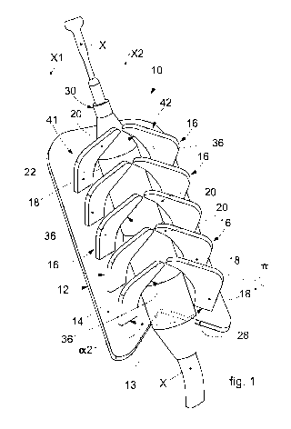
- fig. 1 is a perspective view of a clamping device in accordance with
embodiments of the present invention;
- fig. 2 is a perspective view of a clamping device according to a possible
variant
CA 03054770 2019-08-27
WO 2018/158791 PCT/IT2018/050033
- 7 -
embodiment;
- fig. 3 is a plan view of a clamping device according to another variant
embodiment;
- fig. 4 is a front view of the clamping device in fig. 3;
- fig. 5 is a view in detail of a part of the device in fig. 3;
- fig. 6 is a section view along the line VI-VI of fig. 5;
- figs. 7-9 show front views of a clamping device in accordance with
possible
variant embodiments,
- fig. 10 is a perspective view of a clamping device according to another
variant
embodiment.
To facilitate comprehension, the same reference numbers have been used,
where possible, to identify identical common elements in the drawings. It is
understood that elements and characteristics of one embodiment can
conveniently
be incorporated into other embodiments without further clarifications.
DETAILED DESCRIPTION OF SOME EMBODIMENTS
Embodiments described here with reference to figs. 1-5 concern a clamping
device 10 which allows to easily and temporarily clamp objects 30 or
instruments, in particular with sizes suitable for being handled by an
operator.
By way of example, the clamping device 10 can be advantageously used to
clamp objects 30 such as pens, pencils, scissors, screwdrivers, scalpels,
syringes,
pliers, handpieces and electro-medical probes, and suchlike, although it is
not
excluded that it can be used to clamp different objects or articles preferably
having an oblong shape, for example endoscopes, or other instruments or tools.
The clamping device 10 according to the invention can preferably be applied
in the medical sector, for example in operating theaters, even if other
applications
and uses are not excluded. The clamping device 10 can advantageously be used
in work stations which require the use of several instruments, tools, and
devices
to perform certain operations, or suchlike.
The clamping device 10 allows to temporarily hold and clamp an object in a
desired position, possibly also on inclined or moving planes, preventing it
from
sliding toward the ground.
The clamping device 10 comprises a support plate 12 provided with a first
surface 13 suitable to be rested on a support surface, for example a work
table, or
CA 03054770 2019-08-27
WO 2018/158791 PCT/IT2018/050033
- 8 -
an operating table, or, possibly, on a patient, and a second surface 14,
opposite
the first surface 13, on which a plurality of clamping members are disposed in
the
form of shaped platelets 16.
According to some embodiments, the support plate 12 is made of materials
and sizes suitable to make it flexible, so as to be able to deform and adapt
even to
support surfaces which are not flat and which have undulations, hollows or
protrusions.
According to preferred embodiments, the support plate 12 can be made by
molding polymer material, for example polyurethane, or silicone materials.
These
materials can be sterilized, making the clamping device 10 suitable for use in
medical rooms and operating theaters.
According to other embodiments, the thickness of the support plate 12 can be
comprised, for example, between 2mm and 8mm depending on the type of
material and its characteristics of flexibility and elasticity.
For example, in the case of polyurethane or silicone material, the thickness
can
be comprised between about 3mm and about 5mm.
According to some embodiments, on the first surface 13 an adhesive layer, for
example a double-sided adhesive tape, or a glue can be applied, which allows
to
attach the clamping device 10 stably to the support surface on which it is
rested.
This is particularly useful when the clamping device 10 is used in an
operating
theater, allowing it to be attached directly on a cloth or sheet of the
operating
field.
According to possible variants, it can be provided that the support plate 12
is
provided with magnetic elements, for example magnetic bands or segments,
possibly incorporated in the polymer material, which act as a magnet. In this
way, the clamping device 10 can be attached to shelves or work surfaces having
magnetic properties.
According to these embodiments, the magnetic bands or segments can be
positioned distanced from each other, so as to allow the support plate 12 to
bend
and adapt even to non-flat support surfaces.
According to some embodiments, the shaped platelets 16 are made of flexible
material and can bend and deform to adapt and hold the objects 30 to be
clamped.
According to some embodiments, the shaped platelets 16 can be made of
CA 03054770 2019-08-27
WO 2018/158791 PCT/IT2018/050033
- 9 -
plastic material, for example, polyurethane, silicone material, or suchlike,
which
can be advantageously sterilized so as to make it suitable for use also in
protected
environments such as, for example, medical surgeries, operating theaters and
sterile or pressurized chambers.
In particular, it can be provided that the clamping device 10 is completely
made of polymer or plastic material, of the sterilizable type, so that it can
also be
used in magnetic resonance machines, or during the execution of X-rays on a
patient, without having to remove it in advance.
The shaped platelets 16 can be stably attached to the support plate 12, or
made
in a single body with it.
According to some embodiments, the shaped platelets 16 are each disposed on
a lying plane n orthogonal to the second surface 14 of the support plate 12.
According to some embodiments, the shaped platelets 16 have a flat
development on the respective lying plane a.
According to some embodiments, the clamping device 10 comprises at least
one pair of shaped platelets 16 disposed facing one another.
According to some embodiments, the clamping device 10 comprises a first
group 41 and a second group 42 of shaped platelets, disposed aligned along
respective positioning axes X 1, X2 parallel to one another.
According to some embodiments, the lying planes 7G of the shaped platelets 16
are inclined with respect to the longitudinal axis X by an angle of
inclination a 1
comprised between 10`pand 80 .
According to variant embodiments, the lying planes 7C of the shaped platelets
16 are inclined with respect to the longitudinal axis X by an angle of
inclination
al comprised between 20 and 70 .
According to other variant embodiments, the lying planes n of the shaped
platelets 16 are inclined with respect to the longitudinal axis X by an angle
of
inclination al comprised between 30 and 60 .
The angle of inclination al can be chosen, for example, depending on the size
of the objects 30 to be held.
According to some embodiments, the shaped platelets 16 of the first group 41
are facing those of the second group 42.
According to some embodiments, the shaped platelets 16 are positioned two
CA 03054770 2019-08-27
WO 2018/158791 PCT/IT2018/050033
- 10 -
by two in a specular manner with respect to a longitudinal axis X along the
support plate 12 interposed between the two positioning axes Xl, X2.
According to some embodiments, the shaped platelets 16 are disposed in a
herringbone pattern on two rows with respect to the longitudinal axis X,
forming
.. between them an angle a2.
According to possible solutions, the angle a 2 can be comprised between 20
and 160 , preferably between 40 and 140 .
According to preferred embodiments, the angle a2 can be comprised between
about 60 and about 120 .
Advantageously, the herringbone disposition of the shaped platelets 16 defines
a preferred position for the insertion and removal of the object 30 to be
clamped,
so as to render these operations quick and effective.
According to possible solutions, the shaped platelets 16 of the first group 41
are disposed symmetrical with respect to the shaped platelets 16 of the second
group 42 along the longitudinal axis X.
According to possible variants, the shaped platelets 16 of the first group 41
are
disposed alternately and offset with respect to the shaped platelets of the
second
group, along the longitudinal axis X.
According to some embodiments, the shaped platelets 16 have a profile with at
least one recess and a protruding portion 20, 24, 25 to define a concavity 36
facing, during use, toward the second surface 14.
In particular, the concavities 36 of the shaped platelets 16 of the first
group 41
and of the second group 42 define between them at least one housing
compartment 22 for the object 30 to be held.
According to some embodiments, the housing compartment 22 is aligned
along the longitudinal axis X, interposed between the two positioning axes X
1,
X2 of the first 41 and of the second group 42 of shaped platelets 16.
According to some embodiments described with reference to fig. 1, the shaped
platelets 16 comprise a connection portion 18 with the support plate 12, which
extends in a direction substantially orthogonal to the second surface 14 and
disposed in correspondence with the periphery of the support plate 12.
In this way, between the connection portions 18 of the shaped platelets 16
located respectively in one and the other row, the housing compartment 22 is
CA 03054770 2019-08-27
WO 2018/158791 PCT/IT2018/050033
- 1 1 -
defined in which the objects 30 to be clamped can be inserted.
The shaped platelets 16 also comprise at least a first protruding portion 20
which extends transversely to and above the connection portion 18, and having
a
free end 20a facing the inside of the support plate 12. The first protruding
portions 20 are configured to perform the function of holding the objects 30
inserted in the housing compartment 22, deforming and closing on them.
According to possible embodiments, the upper protruding portion 20 can have
a gradually decreasing section from the connection portion 18 toward the free
end 20a, so as to be more flexible in correspondence with the central zone of
the
clamping device 10, and to facilitate the introduction/removal of the objects
30.
According to some embodiments, the ends of the upper protruding portions 20
of the shaped platelets 16 of one row can be substantially in contact with the
ends
of the upper protruding portions 20 of the shaped platelets 16 of the second
row.
According to possible variants, the ends of the upper protruding portions 20
of
the shaped platelets 16 of the two opposite rows are distanced by a distance
correlated to the size of the objects 30 to be clamped.
The objects 30 can be inserted and removed from the clamping device 10
several times. To insert an object 30 into the clamping device 10 it is
sufficient to
press it against the upper protruding portions 20, with a pressure sufficient
to
deform them and define a passage opening up to the housing compaitment 22.
When the object 30 is positioned therein, the upper protruding portions 20 can
return to their original shape, holding the object 30 positioned between them.
According to some embodiments, the shaped platelets 16 have a reduced
thickness with respect to their sizes extending on the lying plane a, so as to
be
able to deform even only upon the application of the weight force of an object
30
to be clamped, in order to allow a rapid insertion and rapid removal of the
latter
into/from the clamping device.
By way of example, the shaped platelets 16 can have a thickness comparable
to or less than that of the support plate 12, for example comprised between
lmm
and 5mm, preferably comprised between 1 and 3mm.
The reduced thickness and the conformation of the shaped platelets 16 allows
them to be deformed in any direction, both along the longitudinal axis X and
in a
direction transverse thereto.
CA 03054770 2019-08-27
WO 2018/158791 PCT/IT2018/050033
- 12 -
In this way it is possible to insert/remove the object 30 either by moving it
in
an axial direction in both senses along the longitudinal axis X, or by moving
it
with an upward and downward movement, and vice versa, along a plane
orthogonal to the support plate 12, for example passing through the
longitudinal
axis X.
According to variant embodiments, described with reference to figs. 2-8, the
shaped platelets 16 can also comprise at least one second internal lower
protruding portion 24.
According to possible solutions, the second lower protruding portion 24 can
extend at an intermediate height between the upper protruding portion 20 and
the
support plate 12.
According to possible solutions, the second lower protruding portion 24 can
have an arched shape, having a first end connected to the connection portion
18
in proximity to the support plate 12, and a second free end located at an
intermediate height between the support plate 12 and the upper protruding
portion 20.
According to some embodiments, the second lower protruding portion 24
defines a second concavity 37 facing toward the support plate 12.
According to other embodiments, the upper protruding portion 20 and the
lower protruding portion 24 can define a hollow between them, or a recess 25
defining another clamping member for the objects 30 to be clamped.
The presence of two protruding portions 20, 24 disposed at different heights
with respect to the support plate 12 makes the device suitable to hold and
clamp
objects 30 or instruments of different sizes, in particular preventing them
from
slipping out of the housing compartment 22.
According to other embodiments, shown by way of example in figs. 4 and 5, at
least the lower protruding portion 24 can be provided with at least one
incision
26, or a cut, configured to increase the flexibility of the lower protruding
portion
24 and facilitate the introduction of the objects 30 to be clamped in the
clamping
device 10.
According to some embodiments, the incision 26 extends in a direction
perpendicular to the support plate 12, and acts as a hinge to pivot the lower
protruding portion 24 which can rotate with respect to it in the opposite
direction
CA 03054770 2019-08-27
WO 2018/158791 PCT/IT2018/050033
- 13 -
to the face on which the incision 26 itself is present.
According to some embodiments, the incision 26 makes the lower protruding
portion 24 more flexible in one direction, so as to define a univocal
direction of
use of the clamping device 10 which makes the introduction and removal of
objects 30 into/from it faster and more effective.
The greater flexibility of the lower protruding portion 24 conferred by the
incision 26 allows objects of greater size to be inserted all the way to the
bottom
of the housing compartment 22 of the clamping device 10, in contact with the
second surface 14, and thus to be clamped better by the upper protruding
portions
20.
The incision 26 on the lower protruding portion 24 also allows larger objects
30 to remain clamped in the clamping device 10, preventing the risk that they
can
be expelled therefrom due to lack of sufficient space at the bottom, or in
proximity to the second surface 14.
According to some embodiments, the support plate 12 can have a rectangular
shape, possibly with rounded corners, as shown by way of example in fig. 3.
According to possible variants, for example shown in figs. 1 and 3, the
support
plate 12 can be provided, in the front portion, with a shaped profile provided
with
a recess 28 which can be more or less pronounced, which, if located in
correspondence with an edge of the support surface, can facilitate the
introduction/removal of the objects.
The recess 28 according to some embodiments can have edges with an
inclination correlated with the inclination of the shaped platelets 16.
For example, in the case of objects 30 such as handpieces or other devices
connected to a cable, the cable can be positioned in the recess 28, while the
handpiece, or other device or object 30, is clamped in the clamping device 10.
The recess 28 can also contribute to indicate the best position of use of the
clamping device 10, being preferably facing toward the operator.
According to possible variant embodiments, shown for example in fig. 7, it
can be provided that the support plate 12 is provided with a protrusion, or a
relief
32, disposed along the longitudinal axis X, which extends from the second
surface 14. The protrusion 32 keeps the objects 30 to be clamped partly
distanced
from the support plate 12 itself, reducing the contact surface with the
latter. This
CA 03054770 2019-08-27
WO 2018/158791 PCT/IT2018/050033
- 14 -
can be useful in the case of application of the clamping device 10 in an
operating
theater, where the objects 30 to be clamped could be soiled by biological
fluids.
According to another variant, for example shown in fig. 8, the support plate
12
can be provided with a hollow or groove 34, in which it is possible to collect
any
fluids and biological liquids present on the objects 30 to be clamped.
According to other embodiments, it can be provided that the shaped platelets
16 have several internal lower protruding portions 24a, 24b, which are
flexible
enough to bend and allow objects of different sizes to be housed inside the
device
10.
According to some embodiments, it can be provided that the ends of the
internal lower protruding portions 24a, 24b of respective opposite shaped
platelets 16 are in contact with one another, or slightly distanced.
According to other embodiments, it can be provided that the internal lower
protruding portions 24a, 24b are provided with incisions or cuts 26a, 26b
substantially orthogonal to the support plate 12, or at most slightly
inclined.
The incisions 26a, 26b can be more or less deep, and possibly in a different
position on each of the internal lower protruding portions 24a, 24b, so as to
define different levels of flexibility of the latter.
According to other embodiments, shown by way of example in fig. 10, the
clamping device 10 can comprise two or more pairs of groups of shaped
platelets
16, disposed facing each other in twos, to define two or more housing
compartments 22, each of them suitable to clamp at least one object 30.
According to other embodiments, it can be provided that the sizes of the
shaped platelets 16 in the two pairs of groups are the same, or different, so
as to
define housing compartments 22 that are more or less big, and to make the
clamping device 10 more versatile in relation to the type of object 30 to be
clamped.
It is clear that modifications and/or additions of parts can be made to the
clamping device 10 as described heretofore, without departing from the field
and
scope of the present invention.
It is also clear that, although the present invention has been described with
reference to some specific examples, a person of skill in the art shall
certainly be
able to achieve many other equivalent forms of clamping device, having the
CA 03054770 2019-08-27
WO 2018/158791 PCT/IT2018/050033
- 15 -
characteristics as set forth in the claims and hence all coming within the
field of
protection defined thereby.