Note: Descriptions are shown in the official language in which they were submitted.
CA 03055772 2019-09-06
WO 2018/165646
PCT/US2018/021919
QUICK CONNECT DEVICE FOR RECESSED ELECTRICAL FIXTURES
Field of the Disclosure
The disclosure relates to electrical connectors and fixtures, and more
particularly, to an
electrical plug and socket combination allowing quick connection and mounting
of electrical
fixtures for recessed lighting.
Related Patents and Applications
This disclosure relates to PCT International Patent Application No.
PCT/US2016/032170 filed May 12, 2016 (published as WO 2016/183354 Al); PCT
International Patent Application No. PCT/US2018/020987 filed March 5, 2018;
U.S. Patent
Nos. 7,462,066 filed March 20, 2007; 7,192,303 filed December 2, 2004; and
6,962,498 filed
December 12, 2001; and to U.S. Patent Application Publication No. 20090280673
filed
December 2, 2005; U.S. Provisional Application 62/160,585 filed May 12, 2015;
and U.S.
Provisional Application 62/308,718, filed March 15, 2016, the contents of all
of which are
hereby incorporated by reference herein, in their entirety.
Background of the Disclosure
Traditional techniques for installing electrical fixtures and appliances such
as lighting
fixtures and fans on walls or ceilings usually require the assistance of a
qualified electrician,
and the use of a variety of tools and specialized hardware. The procedure for
installing or
uninstalling such fixtures can also be relatively time consuming, even when
performed by an
experienced installer. In addition to the need for hand-wiring the necessary
electrical
connections between the fixture and electrical power supply wiring, the
installer must make
separate mechanical connections for supporting or suspending the fixture in
place.
The patents identified above in the Related Patents and Applications Section
disclose
solutions to these and other problems. These related patents and applications
disclose various
embodiments of plug and socket combinations that permit quick connection of an
electrical
fixture or appliance at an electrical junction box on a wall or ceiling. The
socket is secured
on the wall or ceiling near electrical power supply wiring and includes female
receptacles
which receive male electrical prongs carried on the plug. The electrical
fixture is secured to
the plug. In addition to the quick electrical connection provided by this plug
and socket
1
CA 03055772 2019-09-06
WO 2018/165646
PCT/US2018/021919
combination, a mechanical connection between the plug and socket carries the
mechanical
load of the electrical fixture.
This disclosure sets forth improvements related to various embodiments of the
plug and
socket combinations in the related patents and applications for use when
recessed lighting is
desired.
Recessed lighting is a versatile means of providing both ambient and task
lighting to just
about any area in home, office, or any desired space. Also known as pot
lighting, can
lighting, or downlights, these lights are mounted in the ceiling or wall (most
often in a
ceiling) rather than surface mounted on the wall or ceiling.
Recessed lighting includes two major components- the housing and the trim,
both
chosen (and oftentimes sold) separately. The housing is what's above the
ceiling, and it
contains all of the electrical components, such as the light source and the
means to mount the
fixture. The trim refers to what we see below the ceiling, such as the trim
style or the parts
that direct the light.
Besides functional differences in the wide variety of recessed lighting
options
commercially available, there are aesthetic ones too. If the look of a round,
white light
fixture, is not appealing for a given application, there are other choices
available. Recessed
lights with trim rings in different colors or metallic finishes are available.
Square lights as
well as different shapes and sizes are available if the round-style is too
plain or conventional.
Summary of the Disclosure
The disclosure relates to a device for connecting an electrical fixture with
electrical
power supply wiring located at or near an electrical junction box positioned
such that a face
of the electrical junction box is substantially flush with a surface, and for
mounting the
fixture on the electrical junction box. The device includes a socket including
a socket body
having at least one internal cavity therein. The socket is configured and
dimensioned to be
positioned in the electrical junction box and securable to the electrical
junction box. An
electrically conductive contact terminal is disposed within the cavity for
establishing an
electrical connection between the electrical power supply wiring and the
socket.
The device also includes a plug fixed to the fixture and insertable into the
socket. The
plug has at least one male connector electrically connected to the fixture and
engageable with
the contact terminal within the socket to establish a circuit between the
electrical fixture and
the electrical power wiring. A releasable latch is carried on the combination
of the plug and
the socket for releasably securing the plug to the socket. The plug and socket
are configured
2
CA 03055772 2019-09-06
WO 2018/165646
PCT/US2018/021919
and dimensioned such that the fixture is positioned against the surface
without a recessed
lighting housing.
In one embodiment, the fixture is a LED PCB light source. The LED PCB can
include a
cover. A rim can be provided on the cover. In an embodiment, the body of the
cover is
transparent or translucent and the rim is opaque. The cover can include a
lens, filter, or other
optical element to create a lighting effect.
In some embodiments, the light source and cover both have a flat profile. In
other
embodiments, at least one of the light source and cover has a domed profile.
The socket can include a mounting strap attached to the socket body for
securing the
socket to the electrical junction box. In an embodiment, the mounting strap is
generally U-
shaped with two legs. In one embodiment, the length of the legs is at least
twice the height of
the socket body. In another embodiment, the length of the legs is about the
same as the
height of the socket body. In a different embodiment, the length of the legs
is adjustable.
The electrical junction box can include a first series of vertically spaced
holes and a
second series of vertically spaced holes, with the first and second series of
vertically spaced
holes on facing surfaces of the electrical junction box.
The disclosure also relates to a plug for coupling with a socket to form a
device for
connecting an electrical fixture with electrical power supply wiring located
at or near an
electrical junction box positioned such that a face of the electrical junction
box is
substantially flush with a surface, and for mounting the fixture on the
electrical junction box.
The plug comprises at least one male connector electrically connected to the
fixture and
engageable with a contact terminal within the socket to establish a circuit
between the
electrical fixture and the electrical power wiring. A releasable latch is
carried on the
combination of the plug and the socket for releasably mounting the fixture on
the support.
The plug and socket are configured and dimensioned such that the fixture is
positioned
against the surface without a recessed lighting housing.
The disclosure also relates to a socket for a recessed lighting housing to
mechanically
and electrically couple an electrical fixture fixed to a plug. The socket
comprises: an
extender having an Edison type base on a first end and a socket body on a
second end, the
Edison type base threadably connectable to threading of housing to
mechanically and
electrical couple the socket to the housing; and a socket body on a second end
of the
extender, the socket body having at least one internal cavity therein and an
electrically
conductive contact terminal disposed within the cavity for establishing an
electrical
connection between the housing and the socket. A releasable latch is carried
on the
3
CA 03055772 2019-09-06
WO 2018/165646
PCT/US2018/021919
combination of the plug and the socket for releasably securing the plug to the
socket.
In one embodiment, the extender has a fixed length. In another embodiment, the
extender has an adjustable length.
Brief Description of the Drawings
A more complete understanding of the present disclosure, and the attendant
advantages
and features thereof, will be more readily understood by reference to the
following detailed
description when considered in conjunction with the accompanying drawings
(which form an
integral part of the description and are to be read in conjunction therewith,
and in which like
reference numerals are employed to designate identical components in the
various views)
wherein:
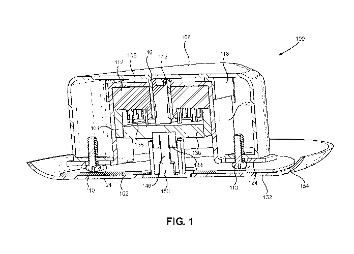
FIG. 1 is a sectional view of an embodiment of a recessed lighting plug and
socket
(receptacle) of a quick connect device according to the disclosure. The socket
is installed in
an electrical junction box and the plug is mechanically and electrically
connected to the
socket.
FIG. 2 is a front perspective view of the recessed lighting plug and socket of
FIG. 1.
FIG. 3 is a back perspective view of the recessed lighting plug and socket of
FIG. 1.
FIG. 4 is a perspective view of the socket of FIG. 1 prior to installation in
the electrical
junction box.
FIG. 5 is a side view of the socket of FIG. 1 prior to installation in the
electrical junction
box.
FIG. 6 is a front view of the socket of FIG. 1 prior to installation in the
electrical
junction box.
FIG. 7 is a back view of the socket of FIG. 1 prior to installation in the
electrical
junction box.
FIG. 8 is perspective view of the socket of FIG. 1 installed in an electrical
junction box.
FIG. 9 is sectional view of the socket of FIG. 1 installed in an electrical
junction box.
FIG. 10 is front view of the socket of FIG. 1 installed in an electrical
junction box.
FIG. 11 is a perspective view of the plug of FIG. 1.
FIG. 12 is a sectional view of the plug of FIG. 1.
FIG. 13 is a back view of the plug of FIG. 1.
FIG. 14 is a front view of the plug of FIG. 1.
FIG. 15 is a side view of the plug of FIG. 1.
4
CA 03055772 2019-09-06
WO 2018/165646
PCT/US2018/021919
FIG. 16 is a sectional view of another embodiment of a recessed lighting plug
and
socket (receptacle) of a quick connect device according to the disclosure. The
socket is
installed in an electrical junction box and the plug is mechanically and
electrically connected
to the socket.
FIG. 17 is a perspective view of the recessed lighting plug and socket of FIG.
16.
FIG. 18 is a perspective view of the plug of FIG. 16.
FIG. 19 is a sectional view of the plug of FIG. 16.
FIG. 20 is a back view of the plug of FIG. 16.
FIG. 21 is a front view of the plug of FIG. 16.
FIG. 22 is a side view of the plug of FIG. 16.
FIG. 23 is a sectional view of another embodiment of a recessed lighting plug
and
socket (receptacle) of a quick connect device according to the disclosure. The
socket is
installed in an electrical junction box and the plug is mechanically and
electrically connected
to the socket.
FIG. 24 is another sectional view of the recessed lighting plug and socket of
FIG. 23.
FIG. 25 is a front perspective view of the recessed lighting plug and socket
of FIG. 23.
FIG. 26 is a back perspective view of the recessed lighting plug and socket of
FIG. 23.
FIG. 27 is a front view of the electrical junction box of FIG. 23.
FIG. 28 is a perspective view of the electrical junction box of FIG. 23.
FIG. 29 is a perspective view of the socket installed in the electrical
junction box of
FIG. 23.
FIG. 30 is a top view of the socket installed in the electrical junction box
of FIG. 23.
FIG. 31 is a sectional view of the socket installed in the electrical junction
box of FIG.
23.
FIG. 32 is a perspective view of another embodiment of a socket installed in
an
electrical junction box.
FIG. 33 is a sectional view of the socket of FIG. 32 installed in the
electrical junction
box.
FIG. 34 is a front view of the socket of FIG. 32 installed in the electrical
junction box.
FIG. 35 is a perspective view of an embodiment of a plug and socket
combination that
can be used in an existing recessed lighting housing.
FIG. 36 is a perspective view of the plug and socket combination of FIG. 35
with the
plug disconnected from the socket.
FIG. 37 is a sectional view of the plug and socket combination of FIG. 35.
5
CA 03055772 2019-09-06
WO 2018/165646
PCT/US2018/021919
FIG. 38 is a sectional view of the plug and socket combination of FIG. 35 with
the plug
disconnected from the socket.
FIG. 39 is a front view of the socket of FIG. 35.
FIG. 40 is a sectional view of the socket of FIG. 35.
Detailed Description
As required, embodiments are disclosed herein; however, it is to be understood
that the
disclosed embodiments are merely examples and that the devices and methods
described
below can be embodied in various forms. Therefore, specific structural and
functional details
disclosed herein are not to be interpreted as limiting, but merely as a
representative basis for
teaching one skilled in the art to variously employ the present subject matter
in virtually any
appropriately detailed structure and function. Further, the terms and phrases
used herein are
not intended to be limiting, but rather, to provide an understandable
description of the
concepts.
The terms "a" or "an", as used herein, are defined as one or more than one.
The term
plurality, as used herein, is defined as two or more than two. The term
another, as used
herein, is defined as at least a second or more. The terms "including" and
"having," as used
herein, are defined as comprising (i.e., open language). The term "coupled,"
as used herein, is
defined as "connected," although not necessarily directly, and not necessarily
mechanically.
The disclosure herein relates to the inventor's prior work, such as that set
forth above in
the documents identified in the Related Patents and Applications section, the
contents of each
of which are herein incorporated in their entirety by reference. In this
regard, the plug and/or
socket can include a sensing unit for at least one of wirelessly communicating
a sensed
condition and wirelessly receiving a signal as disclosed in PCT International
Patent
Application No. PCT/US2016/032170 filed May 12, 2016 and PCT International
Patent
Application No. PCT/US2018/020987 filed March 5, 2018.
Referring first to FIGS. 1-3, a quick connect device 100 for installing
electrical fixtures,
which in this embodiment is a light source 102, comprises the combination of a
plug 104 and
mating socket 106. Plug 104 and socket 106 are configured and dimensioned so
that together
with light source 102, the look and effect of a recessed lighting fixture are
achieved with only
a standard electrical junction box and without any type of recessed lighting
housing. The
disclosure contemplates that electrical fixtures other than a light source can
be used with
device 100. Such fixtures or electrical fixtures include, but are not limited
to, a camera,
6
CA 03055772 2019-09-06
WO 2018/165646
PCT/US2018/021919
security device or any other device which is powered by electricity supplied
by electrical
wiring, and which requires a mechanical connection to support or suspend the
fixture.
Device 100 functions to both establish an electrical connection between
lighting source
102 and electrical supply wiring (located at or near electrical junction box
108), and
mechanically support lighting source 102 in electrical junction box 108
located on a surface
or base, typically the ceiling, but could also be a wall or floor surface.
Plug 104 is fixedly
secured to lighting source 102, while socket 106 is secured to electrical
junction box 108 with
screws 110. Although lighting source 102 is shown as an LED PCB, the
disclosure
contemplates the use on any suitable lighting source.
Unless otherwise shown or described herein, the structure, function, and
operation of
plug 104 and mating socket 106 have already been detailed in, for example, the
patents and
application incorporated by reference herein. Accordingly, this disclosure
will focus on the
differences in structure, function, and operation of plug 104 and mating
socket 106 as well as
other related improvements.
As best seen in FIGS. 4-10, socket 106 comprises a substantially cylindrically
shaped
body 112 formed of non-conductive material such as phenolic resin. Concentric,
ring shaped,
female recesses or slots 114 are formed in one face of socket 106, and are
configured to
matingly receive later discussed male connector rings on plug 104 to establish
electrical
connections between plug 104 and socket 106. Socket 106 includes a center
through hole
within which there is fixedly secured a bushing 116. In the illustrated
embodiment, bushing
116 passes through and is fixedly secured to an elongate mounting strap 118 as
by welding. It
should be noted here however, that bushing 116 and strap 118 could be of
unitary
construction, formed of a single piece of high strength material, such as
metal as by casting,
machining or other metal working processes.
Mounting strap 118 is generally U-shaped with a length 120 selected (e.g. at
least twice
the height of socket body 112) so that lighting source 102 creates the look
and effect of a
recessed lighting fixture when installed in electrical junction box 108.
Mounting strap 118 is
provided with an aperture 122 on each of its outer extremities or flanges 124
which receives
screw 100 to affix mounting strap 118, and thus the entire device 100 to
electrical junction
box 108. The U-shaped configuration of strap 118 allows socket 24 to be
recessed within the
junction box, as illustrated in FIGS. 8-10.
Socket body 112 is provided with a circumferential notch 126 defining an
annular face
128 that is intended to engage a later discussed, corresponding face on plug
104 and acts as a
stop to limit the entry of plug 104 into socket 106. Plug 104 and socket 106
are provided with
7
CA 03055772 2019-09-06
WO 2018/165646
PCT/US2018/021919
a plurality of teeth 130 (on a face and/or periphery) that interengage or mesh
when plug 104
and socket 106 are mated to prevent rotating relative to each other. Prior to
the teeth 130 of
the plug 104 and socket 106 engaging, plug 104 and socket 106 are free to
rotate relative to
each other.
Socket body 112 includes tabs 132, with each of tabs 132 having an opening 134
for
receiving an electrical supply wire. The exact size of openings 134 will
depend on the gauge
of the electrical wiring in a given application. The bare, stripped end of the
electrical supply
wire is connected to socket 106 by inserting the wire end into one of the
openings 134. Each
of tabs 132 is electrically connected to a corresponding one of recesses 114
as disclosed in
the patent documents incorporated by reference. Although tabs 132 are shown on
the side of
body 112, in some applications, it may be more convenient or possible to feed
the electrical
supply wires through the top face of socket body 12. In this case, the
electrical supply wires
may be positioned through access openings located on the top of socket body
112, where
again they establish electrical connection to socket 106.
Referring now to FIGS. 11-15, plug 104 includes a body 136 formed out of non-
conductive material and includes a cylindrical cavity 138 in one face thereof.
Concentric,
male connector rings 140 are integrally molded into plug body 136, with
sufficient radial
spacing therebetween to electrically insulate them from each other. The
diameters and
spacing of male connector rings 140 are such that they are alignable with and
receivable
within corresponding female recesses 114 in socket 106. Each of connector
rings 140
includes an extension and electrical wiring from lighting source 102 which is
attached to plug
104 and electrically connected to the extensions to provide power to lighting
source 102.
Plug 104, as well as lighting source 102 attached thereto, is mechanically
connected to
socket 106 and to mounting strap 118 by means of a centrally located,
releasable spindle
assembly 142 which has been described in detail in the incorporated by
reference patent
documents. In brief, spindle assembly 142 includes a barrel 144 having a
series of coaxial
bores therein, and a plunger or pin 146 axially slidable within barrel 144.
Barrel 144 includes
a plurality of retaining balls 148 captured within radial openings in barrel
144. The upper end
of pin 146 is provided with a reduced diameter section forming a recess or
ball detent into
which retaining balls 148 may be inwardly displaced. A compression spring
sleeved over pin
146 normally biases pin 146 to move downwardly (outwardly) into a latched or
locking
position, wherein pin 146 forces retaining balls 148 outwardly until they rest
against a
shoulder within bushing 116. A push button 150, which extends from the lower
end of barrel
144, provides a means of actuating spindle assembly 142 using either a finger
or a tool.
8
CA 03055772 2019-09-06
WO 2018/165646
PCT/US2018/021919
Lighting source 102 may be secured to plug 104 in any of a variety of ways.
For
example, lighting source 102 may be fixedly attached to lower section of
barrel 144. As
shown, lighting source 102 rests on cover 152, which is attached to barrel
144. In any event,
it may be appreciated that the weight of lighting source 102 is transmitted
through barrel 144,
retaining balls 148, and bushing 116 to mounting strap 118, which in turn is
secured to
electrical junction box 108.
Cover 152 can be provided with a rim 154 to create the look of a trim found in
a
recessed lighting fixture. Cover 152 can be clear plastic or glass to allow
the illumination of
lighting source 102 to be transmitted. Cover 152 can be or include a lens,
filter, or other
optical element to create a desired lighting effect.
FIGS. 16-22 show another embodiment of a plug 164 that can be used with socket
106
and electrical junction box 108. Since the embodiment of plug 164 is generally
similar to the
embodiment of plug 104, the same reference numerals are used to designate
similar or
analogous components to avoid confusion. Instead of having a flat profile like
plug 104, plug
164 has a domed profile. It should be noted that the profile can be selected
or changed based
on the profile of lighting source 102 and/or cover 152.
FIGS. 23-26 show another embodiment of a socket 166 and plug 104 combination
that
together with light source 102, create the look and effect of a recessed
lighting fixture. Since
the embodiment of socket 166 is generally similar to the embodiment of socket
106, the same
reference numerals are used to designate similar or analogous components to
avoid
confusion. As is readily evident by comparing FIGS. 23-26 and 29-31 to FIGS. 1-
10, length
120 of mounting strap 118 differs. For socket 106, the length is extended
(i.e. much longer
than the height of socket body 112), while for socket 166, the length is
around the same size
as the height of socket body 112, which is consistent with most of the sockets
disclosed in the
incorporated by reference patent documents.
For socket 166, the look and effect of a recessed lighting fixture is achieved
in
combination with an electrical junction box 168. As an initial matter, it
should be noted that
electrical junction box 168 can be made by modifying (either at the
installation site of light
source 102 or at a manufacturing facility) electrical junction box 108 or
electrical junction
box 168 can be custom made. Referring primarily to FIGS. 27 and 28, electrical
junction box
168 has a series of vertically spaced holes 170 in each corner. Although holes
170 are shown
in each corner, holes 170 may be provided in only two opposite corners.
Further, holes 170
can be located away from the corner as long as there are at least two opposite
(or facing)
9
CA 03055772 2019-09-06
WO 2018/165646
PCT/US2018/021919
series of holes 170. The position and spacing of each of holes 170 is selected
for a desired
vertical position of plug 164 within electrical junction box 168.
A bracket 172 is fixed to a side (or one of the corners) of electrical
junction box 168 and
another bracket 172 is fixed opposite the first bracket. Machine screws 174
(which insert into
one of holes 170) can be used to secure brackets 172 to electrical junction
box 168. The
disclosure contemplates other methods (such as those used to position a shelf
in a cabinet) of
securing brackets 172 so long as the brackets can be moved to different holes
170 if a
different position is desired.
Bracket 172 includes a screw hole 176 for receiving screw 110, when socket 166
is
positioned in electrical junction box 168, aperture 122 on flange 124 aligns
with screw hole
176 to secure socket 166 to electrical junction box 168 (FIGS. 29-31). As
previously noted,
the specific hole 170 used is determined so that when plug 104 is coupled to
socket 166, light
source 102 provides the look and effect of a recessed lighting fixture.
FIGS. 32-34 show another embodiment of a socket 186 and plug 104 combination
that
together with light source 102, create the look and effect of a recessed
lighting fixture. Since
the embodiment of socket 186 is generally similar to the previous disclosed
embodiments of
the socket, the same reference numerals are used to designate similar or
analogous
components to avoid confusion. Although electrical junction box 108 is shown
(i.e. socket
186 is designed to be used with a standard electrical junction box),
electrical junction box 168
can be used as well.
Socket 186 has a mounting strap 118 that has an adjustable length so that
socket 186 can
be positioned as deep or as shallow in electrical junction box 108 as is
needed to achieve the
look and effect of a recessed lighting fixture when plug 104 and lighting
source 102 are
coupled to socket 186. Although a particular mechanism for adjusting the
length of mounting
strap 118 (i.e. a set screw 188 to fix two legs 190, 192 at any one of a
plurality of discrete
positions), any suitable mechanism that provides an adjustable length (either
in discrete
positions or a continuum of positions) could be used.
FIGS. 35-40 show an embodiment of a plug and socket combination that can be
used
with an existing conventional recessed lighting housing 200. An extender 202
has an Edison
type base 204 and screws into the threading 204 of housing 200. Extender 202
can have a
fixed length or a variable length (as shown). Other mechanisms of changing the
length of
extender 202 are contemplated. Extender 202 is mechanically and electrically
connected to
socket 106. When plug 104 and lighting source 102 are attached, the look and
effect of a
CA 03055772 2019-09-06
WO 2018/165646
PCT/US2018/021919
recessed lighting fixture is achieved. This may be useful, for example, if
regulations require
a safety device, such as plug 104 and socket 106.
As shown in FIGS. 35-40, a spring 206 is located inside housing 208, which
includes
first and second telescoping portions 210, 212. Spring 206 biases extender 202
in an
extended position and can be adjusted to a shorter length by screw 214. Wiring
216 (shown
only in FIG. 37 for clarity) that conducts electricity from housing through
Edison base 204 to
socket 106 can be located outside of or within the space encircled by spring
206 or can be
located inside spring 206 itself.
All references cited herein are expressly incorporated by reference in their
entirety. It
will be appreciated by persons skilled in the art that the present disclosure
is not limited to
what has been particularly shown and described herein above. In addition,
unless mention
was made above to the contrary, it should be noted that all of the
accompanying drawings are
not to scale. There are many different features to the present disclosure and
it is
contemplated that these features may be used together or separately. Thus, the
disclosure
.. should not be limited to any particular combination of features or to a
particular application
of the disclosure. Further, it should be understood that variations and
modifications within the
spirit and scope of the disclosure might occur to those skilled in the art to
which the
disclosure pertains. Accordingly, all expedient modifications readily
attainable by one versed
in the art from the disclosure set forth herein that are within the scope and
spirit of the present
disclosure are to be included as further embodiments of the present
disclosure.
11