Note: Descriptions are shown in the official language in which they were submitted.
CA 03055808 2019-09-06
WO 2018/165316
PCT/1JS2018/021367
GRAIN REFINING WITH DIRECT VIBRATIONAL COUPLING.
BACKGROUND
CROSS-REFERENCE TO RELATED APPLICATIONS
This application claims priority to U.S. Serial No. 62/468,709 (the entire
contents of
which are incorporated herein by reference), filed March 8, 2017, entitled
Grain Refining
with Direct Vibrational Coupling.
This application is related to U.S. Serial No. 62/372,592 (the entire contents
of which
are incorporated herein by reference) filed August 9, 2016, entitled
ULTRASONIC GRAIN
REFINING AND DEGASSING PROCEDURES AND SYSTEMS FOR METAL CASTING.
This application is related to U.S. Serial No. 62/295,333 (the entire contents
of which are
incorporated herein by reference) filed February 15, 2016, entitled ULTRASONIC
GRAIN
REFINING AND DEGASSING FOR METAL CASTING. This application is related to U.S.
Serial No. 62/267,507 (the entire contents of which are incorporated herein by
reference) filed
December 15, 2015, entitled ULTRASONIC GRAIN REFINING AND DEGASSING OF
MOLTEN METAL. This application is related to U.S. Serial No. 62/113,882 (the
entire
contents of which are incorporated herein by reference) filed February 9,
2015, entitled
ULTRASONIC GRAIN REFINING. This application is related to U.S. Serial No.
62/216,842 (the entire contents of which are incorporated herein by reference)
filed
September 10, 2015, entitled ULTRASONIC GRAIN REFINING ON A CONTINUOUS
CASTING BELT. This application is related to PCT/2016/050978 (the entire
contents of
which are incorporated herein by reference) filed September 9, 2016, entitled
ULTRASONIC
GRAIN REFINING AND DEGASSING PROCEDURES AND SYSTEMS FOR METAL
CASTING. This application is related to U.S. Serial No. 15/337,645 (the entire
contents of
which are incorporated herein by reference) filed October 28, 2016, entitled
ULTRASONIC
GRAIN REFINING AND DEGASSING PROCEDURES AND SYSTEMS FOR METAL
CASTING.
This application is related to U.S. Serial No. 62/460,287 (the entire contents
of which
are incorporated herein by reference) filed Februaryl 7, 2017, entitled
ULTRASONIC GRAIN
CA 03055808 2019-09-06
WO 2018/165316 PCT/US2018/021367
REFINING AND DEGASSING PROCEDURES AND SYSTEMS FOR METAL CASTING
INCLUDING ENHANCED VIBRATIONAL COUPLING.
Field
6 The present invention is related to a method for producing metal
castings with
controlled grain size, a system for producing the metal castings, and products
obtained by the
metal castings.
Description of the Related Art
Considerable effort has been expended in the metallurgical field to develop
techniques for casting molten metal into continuous metal rod or cast
products. Both batch
casting and continuous castings are well developed. There are a number of
advantages of
continuous casting over batch castings although both are prominently used in
the industry.
In the continuous production of metal cast, molten metal passes from a holding
furnace into a series of launders and into the mold of a casting wheel where
it is cast into a
metal bar. The solidified metal bar is removed from the casting wheel and
directed into a
rolling mill where it is rolled into continuous rod. Depending upon the
intended end use of
the metal rod product and alloy, the rod may be subjected to cooling during
rolling or the rod
may be cooled or quenched immediately upon exiting from the rolling mill to
impart thereto
the desired mechanical and physical properties. Techniques such as those
described in U.S.
Pat. No. 3,395,560 to Cofer et al. (the entire contents of which are
incorporated herein by
reference) have been used to continuously-process a metal rod or bar product.
U.S. Pat. No. 3,938,991 to Sperry et al. (the entire contents of which are
incorporated
herein by reference) shows that there has been a long recognized problem with
casting of
"pure" metal products. By "pure" metal castings, this term refers to a metal
or a metal alloy
formed of the primary metallic elements designed for a particular conductivity
or tensile
strength or ductility without inclusion of separate impurities added for the
purpose of grain
control.
Grain refining is a process by which the crystal size of the newly formed
phase is
reduced by either chemical or physical/mechanical means. Grain refiners are
usually added
into molten metal to significantly reduce the grain size of the solidified
structure during the
solidification process or the liquid to solid phase transition process.
2
1
CA 03055808 2019-09-06
WO 2018/165316
PCT/US2018/021367
Indeed, a WIPO Patent Application WO/2003/033750 to Boily et al. (the entire
contents of which are incorporated herein by reference) describes the specific
use of "grain
refiners." The '750 application describes in their background section that, in
the aluminum
industry, different grain refiners are generally incorporated in the aluminum
to form a master
alloy. A typical master alloys for use in aluminum casting comprise from 1 to
10% titanium
and from 0.1 to 5% boron or carbon, the balance consisting essentially of
aluminum or
magnesium, with particles of TiB2 or TiC being dispersed throughout the matrix
of
aluminum. According to the '750 application, master alloys containing titanium
and boron
can be produced by dissolving the required quantities of titanium and boron in
an aluminum
melt. This is achieved by reacting molten aluminum with KBF4 and K2TiF6 at
temperatures
in excess of 800 C. These complex halide salts react quickly with molten
aluminum and
provide titanium and boron to the melt.
The '750 application also describes that, as of 2002, this technique was used
to
produce commercial master alloys by almost all grain refiner manufacturing
companies.
Grain refiners frequently referred to as nucleating agents are still used
today. For example,
one commercial supplier of a TIBOR master alloy describes that the close
control of the cast
structure is a major requirement in the production of high quality aluminum
alloy products.
Prior to this invention, grain refiners were recognized as the most effective
way to
provide a fine and uniform as-cast grain structure. The following references
(all the contents
of which are incorporated herein by reference) provide details of this
background work:
Abramov, 0.V, (1998), "High-Intensity Ultrasonics," Gordon and Breach
Science Publishers, Amsterdam, The Netherlands, pp. 523-552.
Alcoa, (2000), "New Process for Grain Refinement of Aluminum," DOE
Project Final Report, Contract No. DE-FC07-981D13665, September 22,
2000.
Cui, Y, Xu, C.L. and Han, Q., (2007), "Microstructure Improvement in Weld
Metal Using Ultrasonic Vibrations, Advanced Engineering Materials," v. 9,
No. 3, pp.161-163.
Eskin, G.I., (1998), "Ultrasonic Treatment of Light Alloy Melts," Gordon and
Breach Science Publishers, Amsterdam, The Netherlands.
Eskin, G. 1. (2002) "Effect of Ultrasonic Cavitation Treatment of the Melt on
the Microstructure Evolution during Solidification of Aluminum Alloy Ingots,"
Zeitschrift Fur Metallkunde/Materials Research and Advanced Techniques,
v.93, n.6, June, 2002, pp. 502-507.
3
CA 03055808 2019-09-06
WO 2018/165316
PCT/US2018/021367
Greer, A.L., (2004), "Grain Refinement of Aluminum Alloys," in Chu, MG.,
Granger, D.A., and Han, Q., (eds.), " Solidification of Aluminum Alloys,"
Proceedings of a Symposium Sponsored by TMS (The Minerals, Metals &
Materials Society), TMS, Warrendale, PA 15086-7528, pp. 131-145.
Han, Q., (2007), The Use of Power Ultrasound for Material Processing,"
Han, Q., Ludtka, G., and Zhai, Q., (eds), (2007), "Materials Processing under
the Influence of External Fields," Proceedings of a Symposium Sponsored by
TMS (The Minerals, Metals & Materials Society), TMS, Warrendale, PA
15086-7528, pp. 97-106.
Jackson, KA., Hunt, JD., and Uhlmann, D.R., and Seward, T.P., (1966), "On
Origin of Equiaxed Zone in Castings," Trans. Metall. Soc. AIME, v. 236,
pp.149-158.
Jian, X, Xu, H., Meek, TT, and Han, Q., (2005), "Effect of Power Ultrasound
on Solidification of Aluminum A356 Alloy," Materials Letters, v. 59, no. 2-3,
pp. 190-193.
Keles, 0. and Dundar, M, (2007). "Aluminum Foil: Its Typical Quality
Problems and Their Causes," Journal of Materials Processing Technology, v.
186, pp. I 25-137.
Liu, C., Pan, Y, and Aoyama, S., (1998), Proceedings of the 5" International
Conference on Semi-Solid Processing of Alloys and Composites, Eds.: Bhasin,
A.K., Moore, J.J, Young, K P., and Madison, S., Colorado School of Mines,
Golden, CO, pp. 439-447.
Megy, J, (1999), "Molten Metal Treatment," US Patent No. 5,935,295,
August, 1999
Megy, J., Granger, D.A., Sigworth, G.K., and Durst, CR., (2000),
"Effectiveness of In-Situ Aluminum Grain Refining Process," Light Metals,
pp. 1-6.
Cui et al., "Microstructure Improvement in Weld Metal Using Ultrasonic
Vibrations," Advanced Engineering Materials, 2007, vol. 9, no. 3, pp. 161-
163.
Han et al., "Grain Refining of Pure Aluminum," Light Metals 2012, pp. 967-
971.
Prior to this invention, U.S. Pat. Nos. 8,574,336 and 8,652,397 (the entire
contents of
each patent are incorporated herein by reference) described methods for
reducing the amount
of a dissolved gas (and/or various impurities) in a molten metal bath (e.g.,
ultrasonic
4
CA 03055808 2019-09-06
WO 2918/165316
PCT/US2018/021367
degassing) for example by introducing a purging gas into the molten metal bath
in close
proximity to the ultrasonic device. These patents will be referred to
hereinafter as the '336
patent and the '397 patent.
SUMMARY
In one embodiment of the present invention, there is provided a molten metal
conveyor
having a receptor plate in contact with molten metal during transport of the
molten metal.
The receptor plate extends from an entrance where molten metal enters onto the
receptor plate
to an exit where molten metal exits the receptor plate. The molten metal
conveyor has at least
one vibrational energy source which supplies vibrational energy directly to
the receptor plate
in contact with molten metal.
In one embodiment of the present invention, there is provided a method for
forming a
metal product that includes providing molten metal onto a molten conveyor;
cooling the
molten metal by control of a cooling medium flowing through a cooling passage
in the or
attached to the conveyor; and coupling vibrational energy directly into a
receptor plate in
contact with the molten metal on the conveyor.
It is to be understood that both the foregoing general description of the
invention and
the following detailed description are exemplary, but are not restrictive of
the invention.
BRIEF DESCRIPTION OF THE DRAWINGS
A more complete appreciation of the invention and many of the attendant
advantages
thereof will be readily obtained as the same becomes better understood by
reference to the
following detailed description when considered in connection with the
accompanying
drawings, wherein:
Figure 1 is a schematic of a continuous casting mill according to one
embodiment of
the invention;
Figure 2 is a schematic of a molten metal conveyor having multiple
magnetostrictive
transducers attached along a longitudinal length of a vibratory plate;
Figure 3 is a schematic of a molten metal conveyor having a piezoelectric
ultrasonic
transducer attached to a vibratory plate 54;
CA 03055808 2019-09-06
WO 2018/165316
PCT/US2018/021367
Figure 4 is a schematic of multiple transducers attached in a two dimensional
array to
a bottom of vibratory plate;
Figure 5 is a schematic of multiple transducers attached to a bottom of
vibratory plate
with a higher density at the end of the vibratory plate dispensing the molten
metal;
Figure 6A is a side view of metal conveyor showing interior channels for the
cooling
medium to flow therein;
Figure 6B is a view of a metal conveyor/ pouring device according to the
invention;
Figure 7 is a schematic of a casting wheel configuration according to one
embodiment
of the invention utilizing a molten metal processing device in the casting
wheel;
Figure 8 is a schematic of a casting wheel configuration according to one
embodiment
of the invention showing a vibrational probe device coupled directly to the
molten metal cast
in the casting wheel;
Figure 9 is a schematic of a stationary mold utilizing the vibrational energy
sources of
the invention;
Figure 10A is a cross sectional schematic of selected components of a vertical
casting
mill;
Figure 10B is a cross sectional schematic of other components of a vertical
casting
mill;
Figure 10C is a cross sectional schematic of other components of a vertical
casting
mill;
Figure 10D is a cross sectional schematic of other components of a vertical
casting
mill;
Figure 11 is a schematic of an embodiment of the invention utilizing both
ultrasonic
degassing and ultrasonic grain refinement;
Figure 12 is a schematic of an illustrative computer system for the controls
and
controllers depicted herein;
Figure 13 is a flow chart depicting a method according to one embodiment of
the
invention;
Figure 14 is an ACSR wire process flow diagram;
Figure 15 is an ACSS wire process flow diagram; and
Figure 16 is an aluminum strip process flow diagram;
DETAILED DESCRIPTION
6
CA 03055808 2019-09-06
WO 2018/165316
PCT/US2018/021367
Grain refining of metals and alloys is important for many reasons, including
maximizing ingot casting rate, improving resistance to hot tearing, minimizing
elemental
segregation, enhancing mechanical properties, particularly ductility,
improving the finishing
characteristics of wrought products and increasing the mold filling
characteristics, and
decreasing the porosity of foundry alloys. Usually grain refining is one of
the first processing
steps for the production of metal and alloy products, especially aluminum
alloys and
magnesium alloys, which are two of the lightweight materials used increasingly
in the
aerospace, defense, automotive, construction, and packaging industry. Grain
refining is also
an important processing step for making metals and alloys castable by
eliminating columnar
grains and forming equiaxed grains.
Grain refining is a solidification processing step by which the crystal size
of the solid
phases is reduced by either chemical, physical, or mechanical means in order
to make alloys
castable and to reduce defect formation. Currently, aluminum production is
grain refined
using TIBOR, resulting in the formation of an equiaxed grain structure in the
solidified
aluminum. Prior to this invention, use of impurities or chemical "grain
refiners" was the only
way to address the long recognized problem in the metal casting industry of
columnar grain
formation in metal castings. Additionally, prior to this invention, a
combination of 1)
ultrasonic degassing to remove impurities from the molten metal (prior to
casting) along and
2) the above-noted ultrasonic grain refining (i.e., at least one vibrational
energy source) had
not been undertaken.
However, there are large costs associated with using TIBOR and mechanical
restraints
due to the input of those inoculants into the melt. Some of the restraints
include ductility,
machinability, and electrical conductivity.
Despite the cost, approximately 68% of the aluminum produced in the United
States is
first cast into ingot prior to further processing into sheets, plates,
extrusions, or foil. The
direct chill (DC) semi-continuous casting process and continuous casting (CC)
process has
been the mainstay of the aluminum industry due largely to its robust nature
and relative
simplicity. One issue with the DC and CC processes is the hot tearing
formation or cracking
formation during ingot solidification. Basically, almost all ingots would be
cracked (or not
castable) without using grain refining.
Still, the production rates of these modern processes are limited by the
conditions to
avoid cracking formation. Grain refining is an effective way to reduce the hot
tearing
tendency of an alloy, and thus to increase the production rates. As a result,
a significant
7
CA 03055808 2019-09-06
WO 2018/165316 PCT/US2018/021367
amount of effort has been concentrated on the development of powerful grain
refiners that can
produce grain sizes as small as possible. Superplasticity can be achieved if
the grain size can
be reduced to the sub- micron level, which permits alloys not only to be cast
at much faster
rates but also rolled/extruded at lower temperatures at much faster rates than
ingots are
processed today, leading to significant cost savings and energy savings.
At present, nearly all aluminum cast in the world either from primary
(approximately
20 billion kg) or secondary and internal scrap (25 billion kg) is grain
refined with
heterogeneous nuclei of insoluble TiB2 nuclei approximately a few microns in
diameter,
which nucleate a fine grain structure in aluminum. One issue related to the
use of chemical
grain refiners is the limited grain refining capability. Indeed, the use of
chemical grain
.
refiners causes a limited decrease in aluminum grain size, from a columnar
structure with
linear grain dimensions of something over 2,500 pm, to equiaxed grains of less
than 200 gm.
Equiaxed grains of 100 pm in aluminum alloys appear to be the limit that can
be obtained
using the chemical grain refiners commercially available.
The productivity can be significantly increased if the grain size can be
further reduced.
Grain size in the sub-micron level leads to superplasticity that makes forming
of aluminum
alloys much easier at room temperatures.
Another issue related to the use of chemical grain refiners is the defect
formation
associated with the use of grain refiners. Although considered in the prior
art to be necessary
for grain refining, the insoluble, foreign particles are otherwise undesirable
in aluminum,
particularly in the form of particle agglomerates ("clusters"). The current
grain refiners,
which are present in the form of compounds in aluminum base master alloys, are
produced by
a complicated string of mining, beneficiation, and manufacturing processes.
The master
alloys used now frequently contain potassium aluminum fluoride (KAIF) salt and
aluminum
oxide impurities (dross) which arise from the conventional manufacturing
process of
aluminum grain refiners. These give rise to local defects in aluminum (e.g.
"leakers" in
beverage cans and "pin holes" in thin foil), machine tool abrasion, and
surface finish
problems in aluminum. Data from one of the aluminum cable companies indicate
that 25% of
the production defects is due to TiB2 particle agglomerates, and another 25%
of defects is due
to dross that is entrapped into aluminum during the casting process. TiB2
particle
agglomerates often break the wires during extrusion, especially when the
diameter of the
wires is smaller than 8 mm.
CA 03055808 2019-09-06
WO 2018/165316
PCT/US2018/021367
Another issue related to the use of chemical grain refiners is the cost of the
grain
refiners. This is extremely true for the production of magnesium ingots using
Zr grain
refiners. Grain refining using Zr grain refiners costs about an extra $1 per
kilogram of Mg
casting produced. Grain refiners for aluminum alloys cost around $1.50 per
kilogram.
Another issue related to the use of chemical grain refiners is the reduced
electrical
conductivity. The use of chemical grain refiners introduces in excess amount
of Ti in
aluminum, causes a substantial decrease in electrical conductivity of pure
aluminum for cable
applications. In order to maintain certain conductivity, companies have to pay
extra money to
use purer aluminum for making cables and wires.
A number of other grain refining methods, in addition to the chemical methods,
have
been explored in the past century. These methods include using physical
fields, such as
magnetic and electro-magnetic fields, and using mechanical vibrations. High-
intensity, low-
amplitude ultrasonic vibration is one of the physical/mechanical mechanisms
that has been
demonstrated for grain refilling of metals and alloys without using foreign
particles.
However, experimental results, such as from Cui et al, 2007 noted above, were
obtained in
small ingots up to a few pounds of metal subjected to a short period of time
of ultrasonic
vibration. Little effort has been carried out on grain refining of CC or DC
casting
ingots/billets using high-intensity ultrasonic vibrations.
As used herein, embodiments of the present invention will be described using
terminologies commonly employed by those skilled in the art to present their
work. These
terms are to be accorded the common meaning as understood by those of the
ordinary skill in
the arts of materials science, metallurgy, metal casting, and metal
processing. Some terms
taking a more specialized meaning are described in the embodiments below.
Nevertheless,
the term "configured to" is understood herein to depict appropriate structures
(illustrated
herein or known or implicit from the art) permitting an object thereof to
perform the function
which follows the "configured to" term. The term "coupled to" means that one
object
coupled to a second object has the necessary structures to support the first
object in a position
relative to the second object (for example, abutting, attached, displaced a
predetermined
distance from, adjacent, contiguous, joined together, detachable from one
another,
dismountable from each other, fixed together, in sliding contact, in rolling
contact) with or
without direct attachment of the first and second objects together.
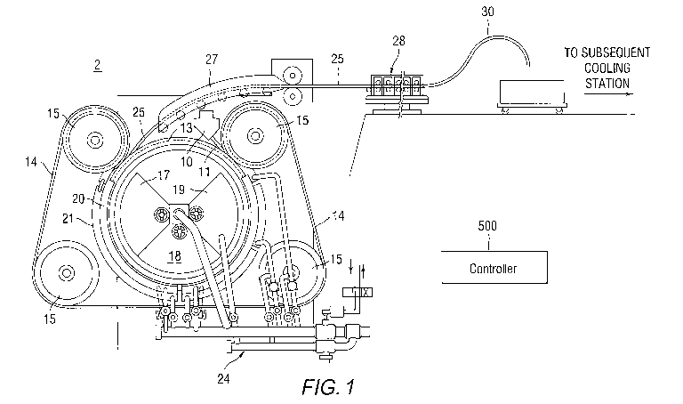
U.S. Pat. No. 4,066,475 to Chia et al. (the entire contents of which are
incorporated
herein by reference) describes a continuous casting process. In general,
Figure 1 depicts
9
CA 03055808 2019-09-06
WO 2018/165316
PCT/US2018/021367
continuous casting system having a casting mill 2 having a delivery device 10
(such as
tundish) which provides molten metal to a pouring spout 11 which directs the
molten metal to
a peripheral groove contained on a rotary mold ring 13. An endless flexible
metal band 14
encircles both a portion of the mold ring 13 as well as a portion of a set of
band-positioning
rollers 15 such that a continuous casting mold is defined by the groove in the
mold ring 13
and the overlying metal band 14. A cooling system is provided for cooling the
apparatus and
effecting controlled solidification of the molten metal during its transport
on the rotary mold
ring 13. The cooling system includes a plurality of side headers 17, 18, and
19 disposed on
the side of the mold ring 13 and inner and outer band headers 20 and 21,
respectively,
.. disposed on the inner and outer sides of the metal band 14 at a location
where it encircles the
mold ring. A conduit network 24 having suitable valving is connected to supply
and exhaust
coolant to the various headers so as to control the cooling of the apparatus
and the rate of
solidification of the molten metal.
By such a construction, molten metal is fed from the pouring spout 11 into the
casting
.. mold and is solidified and partially cooled during its transport by
circulation of coolant
through the cooling system. A solid cast bar 25 is withdrawn from the casting
wheel and fed
to a conveyor 27 which conveys the cast bar to a rolling mill 28. It should be
noted that the
cast bar 25 has only been cooled an amount sufficient to solidify the bar, and
the bar remains
at an elevated temperature to allow an immediate rolling operation to be
performed thereon.
The rolling mill 28 can include a tandem array of rolling stands which
successively roll the
bar into a continuous length of wire rod 30 which has a substantially uniform,
circular cross-
section.
Figure 1 shows controller 500 which controls the various parts of the
continuous
casting system shown therein, as discussed in more detail below. Controller
500 may include
one or more processors with programmed instructions (i.e., algorithms) to
control the
operation of the continuously casting system and the components thereof.
U.S. Pat. No. 9,481,031 to Han etal. (the entire contents of which are
incorporated
herein by reference) describes a molten metal processing device including a
molten metal
containment structure for reception and transport of molten metal along a
longitudinal length
thereof. The device further included a cooling unit for the containment
structure including a
cooling channel for passage of a liquid medium therein, and an ultrasonic
probe disposed in
relation to the cooling channel such that ultrasonic waves are coupled through
the liquid
CA 03055808 2019-09-06
WO 2018/165316
PCT/US2018/021367
medium in the cooling channel and through the molten metal containment
structure into the
molten metal.
As described in the '031 patent, an ultrasonic wave probe provided ultrasonic
vibrations (UV) through the liquid medium and through a bottom plate of a
molten metal
containment structure into which liquid metal was supplied. In the '031
patent, the ultrasonic
wave probe was shown inserted into the liquid medium passage. As described in
the '031
patent, a relatively small amount of undercooling (e.g., less than 10 C.) at
the bottom of the
channel results in a layer of small nuclei of purer aluminum being formed. The
ultrasonic
vibrations from the bottom of the channel creates pure aluminum nuclei which
then are used
as nucleating agents during solidification resulting in a uniform grain
structure. As described
in the '031 patent, the ultrasonic vibrations from the bottom of the channel
disperse these
nuclei and breaks up dendrites that forms in the undercooled layer. These
aluminum nuclei
and fragments of dendrites are then used to form equiaxed grains in the mold
during
solidification resulting in a uniform grain structure.
In one embodiment of the present invention, ultrasonic grain refining involves
application of ultrasonic energy (and/or other vibrational energy) for the
refinement of the
grain size. While the invention is not bound to any particular theory, one
theory is that the
injection of vibrational energy (e.g., ultrasonic power) into a molten or
solidifying alloy can
give rise to nonlinear effects such as cavitation, acoustic streaming, and
radiation pressure.
These nonlinear effects can be used to nucleate new grains, and break up
dendrites during
solidification process of an alloy.
Under this theory, the grain refining process can be divided into two stages:
1)
nucleation and 2) growth of the newly formed solid from the liquid. Spherical
nuclei are
formed during the nucleation stage. These nuclei develop into dendrites during
the growth
stage. Unidirectional growth of dendrites leads to the formation of columnar
grains
potentially causing hot tearing/cracking and non-uniform distribution of the
secondary phases.
This in turn can lead to poor castability. On the other hand, uniform growth
of dendrites in
all directions (such as possible with the present invention) leads to the
formation of equiaxed
grains. Castings/ingots containing small and equiaxed grains have excellent
formability.
Under this theory, when the temperature in an alloy is below the liquidus
temperature;
nucleation may occur when the size of the solid embryos is larger than a
critical size given in
the following equation:
11
CA 03055808 2019-09-06
WO 2018/165316
PCT/US2018/021367
'as/
1' =
Gir
where r* is the critical size, as/ is the interfacial energy associated with
the solid-liquid interface,
and v,AG is the Gibbs free energy associated with the transformation of
a unit volume of liquid
into solid..
Under this theory, the Gibbs free energy, 2-G, decreases with increasing size
of the solid
embryos when their sizes are larger than r*, indicating the growth of the
solid embryo is
thermodynamically favorable. Under such conditions, the solid embryos become
stable nuclei.
However, homogeneous nucleation of solid phase having size greater than r*
occurs only under
extreme conditions that require large undercooling in the melt.
Under this theory, the nuclei formed during solidification can grow into solid
grains
known as dendrites. The dendrites can also be broken into multiple small
fragments by
application of the vibrational energy. The dendritic fragments thus formed can
grow into new
grains and result in the formation of small grains; thus creating an equiaxed
grain structure.
In other words, ultrasonic vibrations transmitted into the undercooled liquid
metal
create nucleation sites in the metals or metallic alloys to refine the grain
size. The nucleation
sites can be generated via the vibrational energy acting as described above to
break up the
dendrites creating in the molten metal numerous nuclei which are not dependent
on foreign
impurities.
Here, in one embodiment of the invention, an ultrasonic device is not
configured to
have ultrasonic waves exclusively coupled through a liquid medium in a cooling
channel and
then through a bottom plate of a molten metal containment structure into the
molten metal.
Instead, in this embodiment, ultrasonic waves are directly coupled to a plate
or receptor in
contact with molten metal.
One or more magnetostrictive ultrasonic devices may be attached directly to
the plate
or receptor in contact with molten metal during transport of the molten metal.
The receptor
plate may extend longitudinally from an entrance where molten metal enters
onto the receptor
plate to an exit where molten metal exits the receptor plate. Indeed, Figure 2
depicts a molten
metal conveyor 50 (sidewalls not shown) having multiple magnetostrictive
transducers 52
attached and evenly spaced apart along a longitudinal length of vibratory
(ultrasonic) plate 54.
The transducers 52 need not be evenly spaced. Furthermore, the transducers can
be spaced
with a lateral separation in a direction of the width of the plate 54. Figure
2 depicts the
12
CA 03055808 2019-09-06
WO 2018/165316
PCT/US2018/021367
surface of the molten metal 53 above plate 54. The molten metal traveling
above plate 54 can
be confined in a flow channel of any shape including rectangular, square, or
round.
In one embodiment of the invention, the thickness of the molten metal
traveling above
plate 54 is less than 10 centimeters thick in one embodiment. In this
embodiment, the
thickness of the molten metal can be less than 1 centimeter. Alternatively,
the thickness of
the molten metal can be less than a half of a centimeter.
Accordingly, the receptor plate 54 can have a lateral width equal to or less
than a
longitudinal length, or the lateral width can be equal to or less than a half
of the longitudinal
length; or the lateral width can be equal to or less than a third of the
longitudinal length. For
example, the receptor plate 54 can have a lateral width between 2.5 cm and 300
cm. The
length of the receptor plate 54 can be between 2.5 cm to 300 cm. Moreover, the
receptor
plate 54 can have a lateral width which tapers down in width toward the exit.
The dimensions
of the receptor plate 54 in one embodiment can vary up to (but not limited to)
220 cm wide
and 70 cm long, although other dimensions can be used. The dimensions may be
inversed
with 220 cm being a length and 70 cm being a width.
Further, the receptor plate 54 can be disposed across a wide range of angular
disposition from a near horizontal orientation (within 20 angular degrees) to
a near vertical
orientation (within 20 angular degrees), with gravity forcing the molten metal
to the exit.
More specifically, the receptor plate 54 can be disposed within 10 angular
degrees (or 5
angular degrees) from a horizontal orientation with gravity forcing the molten
metal to the
exit. Alternatively, the receptor plate 54 can be disposed within 10 angular
degrees (or 5
angular degrees) from a vertical orientation with gravity forcing the molten
metal to the exit.
The surface of the plate on which the molten metal is conveyed (or flows) can
be smooth,
polished, rough, raised, indented, and/or textured. Alternatively, the
receptor plate 54 can be
disposed at any angular position from horizontal (or near horizontal) to
vertical (or near
vertical). This wide angular range permits molten metal to be conveyed along
the receptor
plate 54 whether the vibratory plate is applied in a level pour system or a
down spout scenario
into a casting mold.
In one embodiment of the invention, there is included a controller (e.g.,
controller
500) controlling at least one of a pour rate of the molten metal onto the
receptor plate and/or a
cooling rate of the molten metal on the receptor plate. The controller is
preferably
programmed to adjust the pour rate such that a height of the molten metal
above the receptor
plate is between 1.25 cm and 10 cm, or between 2.5 cm and 5 cm, or between 3
cm and 4 cm.
13
CA 03055808 2019-09-06
WO 2018/165316
PCT/US2018/021367
By having a sheet-like flow of molten metal along the receptor plate 54, the
nuclei induced
and released from the receptor plate 54 can be uniformly dispersed into the
volume of the
molten metal instantaneously on the receptor plate 54. If the surface area of
the receptor plate
is considered as the area available for the generation of the nuclei, then
having a sheet-like
form of molten metal will also serve to cool the molten metal more thoroughly
throughout the
volume of the metal instantaneously on the receptor plate 54. Without
achieving this cooling
throughout, nuclei released could be re-melted into molten metal and loss as
from the total
count of nuclei flowing into the mold or casting wheel. Accordingly, by having
controller
500 control the height of the molten metal on the receptor plate 54, there is
a synergetic effect
when using the sheet-like molten metal in that there are both more nuclei per
unit volume
generated and less nuclei loss due to re-melting.
Components of the molten metal conveyor 50 can be made from a metal such as
titanium, stainless steel alloys, low carbon steels or H13 steel, other high-
temperature
materials, a ceramic, a composite, or a polymer. Components of the molten
metal conveyor
50 can also be made from one or more of niobium, a niobium alloy, titanium, a
titanium alloy,
tantalum, a tantalum alloy, copper, a copper alloy, rhenium, a rhenium alloy,
steel,
molybdenum, a molybdenum alloy, stainless steel, and a ceramic. The ceramic
can be a
silicon nitride ceramic, such as for example a silica alumina nitride or
SIALON.
While not shown in Figure 2, the magnetostrictive transducers 52 have an
internal coil
wrapped around a stack of magnetic layers. The coil provides a high frequency
current
producing a high frequency magnetic field which induces extraction and
compression of the
stack, and thereby impresses vibrations on plate 52.
Magnetostrictive transducers are typically composed of a large number of
material
plates that will expand and contract once an electromagnetic field is applied.
More
specifically, magnetostrictive transducers suitable for the present invention
can include in one
embodiment a large number of nickel (or other magnetostrictive material)
plates or
laminations arranged in parallel with one edge of each laminate attached to
the bottom of a
process container or other surface to be vibrated. A coil of wire is placed
around the
magnetostrictive material to provide the magnetic field. For example, when a
flow of
electrical current is supplied through the coil of wire, a magnetic field is
created. This
magnetic field causes the magnetostrictive material to contract or elongate,
thereby
introducing a sound wave into a fluid in contact with the expanding and
contracting
magnetostrictive material. Typical ultrasonic frequencies from
magnetostrictive transducers
14
CA 03055808 2019-09-06
WO 2018/165316
PCT/US2018/021367
suitable for the invention range from 20 to 200 kHz. Higher or lower
frequencies can be used
depending on the natural frequency of the magnetostrictive element.
For magnetostrictive transducers, nickel is one of the most commonly used
materials.
When a voltage is applied to the transducer, the nickel material expands and
contracts at
ultrasonic frequencies. In one embodiment of the invention, the nickel plates
are directly
silver brazed to a stainless steel plate. With reference to Figure 2, the
stainless steel plate of
the magnetostrictive transducer is the surface that is vibrating at ultrasonic
frequencies and
(as shown in Figure 2 is attached to vibratory (ultrasonic) plate 54.
U.S. Pat. No. 7,462,960 (the entire contents of which are incorporated herein
by
reference) describes an ultrasonic transducer driver having a giant
magnetostrictive element.
Accordingly, in one embodiment of the invention, the magnetostrictive element
can be made
from rare-earth-alloy-based materials such as Terfenol-D and its composites
which have an
unusually large magnetostrictive effect as compared with early transition
metals, such as iron
(Fe), cobalt (Co) and nickel (Ni). Alternatively, the magnetostrictive element
in one
embodiment of the invention can be made from iron (Fe), cobalt (Co) and nickel
(Ni).
Alternatively, the magnetostrictive element in one embodiment of the invention
can
be made from one or more of the following alloys iron and terbium; iron and
praseodymium;
iron, terbium and praseodymium; iron and dysprosium; iron, terbium and
dysprosium; iron,
praseodymium and dysprodium; iron, terbium, praseodymium and dysprosium; iron,
and
erbium; iron and samarium; iron, erbium and samarium; iron, samarium and
dysprosium; iron
and holmium; iron, samarium and holmium; or mixture thereof.
U.S. Pat. No. 4,158,368 (the entire contents of which are incorporated herein
by
reference) describes a magnetostrictive transducer. As described therein and
suitable for the
present invention, the magnetostrictive transducer can include a plunger of a
material
exhibiting negative magnetostriction disposed within a housing. U.S. Pat. No.
5,588,466 (the
entire contents of which are incorporated herein by reference) describes a
magnetostrictive
transducer. As described therein and suitable for the present invention, a
magnetostrictive
layer is applied to a flexible element, for example, a flexible beam. The
flexible element is
deflected by an external magnetic field. As described in the '466 patent and
suitable for the
present invention, a thin magnetostrictive layer can be used for the
magnetostrictive element
which consists of Tb(1-x) Dy(x) Fe2. U.S. Pat. No. 4,599,591 (the entire
contents of which
are incorporated herein by reference) describes a magnetostrictive transducer.
As described
therein and suitable for the present invention, the magnetostrictive
transducer can utilize a
CA 03055808 2019-09-06
WO 2018/165316
PCT/US2018/021367
magnetostrictive material and a plurality of windings connected to multiple
current sources
having a phase relationship so as to establish a rotating magnetic induction
vector within the
magnetostrictive material. U.S. Pat. No. 4,986808 (the entire contents of
which are
incorporated herein by reference) describes a magnetostrictive transducer. As
described
therein and suitable for the present invention, the magnetostrictive
transducer can include a
plurality of elongated strips of magnetostrictive material, each strip having
a proximal end, a
distal end and a substantially V-shaped cross section with each arm of the V
is formed by a
longitudinal length of the strip and each strip being attached to an adjacent
strip at both the
proximal end and the distal end to form and integral substantially rigid
column having a
central axis with fins extending radially relative to this axis.
U.S. Pat. No. 6,150,753 (the entire contents of which are incorporated herein
by
reference) describes ultrasonic transducer assembly, having a cobalt-base
alloy housing with
at least one planar wall section, and at least one ultrasonic transducer
mounted to the planar
wall section, the ultrasonic transducer operatively arranged to impart an
ultrasonic vibrating
force to the planar wall section of the housing. Both the background material
and
descriptions in the '753 patent, describing ways to mount ultrasonic
transducers to stainless
steel plates, can be used in the present invention to form mechanically stable
coupling
between transducers 52/56 and vibratory (ultrasonic) plate 54. For example,
the ULTIMET
brand alloy, available from Haynes International, Inc. of Kokomo, Ind. ULTIMET
is a
cobalt-chromium alloy suitable for the present invention. This alloy has a
nominal chemical
composition (weight percent) as follows: cobalt (54%), chromium (26%), nickel
(9%),
molybdenum (5%), tungsten (2%), and iron (3%). This alloy also contains trace
amounts
(less than 1% weight percent) of manganese, silicon, nitrogen and carbon.
U.S. Pat. No. 5,247,954 (the entire contents of which are incorporated herein
by
reference) describes a method of bonding of the piezoelectric ceramic
transducers which does
not exceed 250 C. This method can be used in the present invention to form
mechanically
stable coupling between transducers 52/56 and vibratory (ultrasonic) plate 54.
For example, a
low temperature brazing alloy is used to bond between a silvered piezoelectric
ceramic
transducers and a pre-metalized surface of plate 54. This solder can be a pre-
formed 96.5%
tin, 3.5% silver, and melts at about 221 C. Such a solder would stick to
silver and
silver/tungsten surfaces which had been fired onto surface of plate 54 prior
to application of
the low temperature solder. The attachment of the piezoelectric ceramic
transducers to plate
54 would then take place in a furnace operating at 230 C.
16
CA 03055808 2019-09-06
WO 2018/165316 PCT/US2018/021367
In one embodiment of the invention, one or more piezoelectric ultrasonic
devices are
attached directly to the plate or receptor in contact with molten metal.
Figure 3 depicts a
molten metal conveyor 50 (sidewalls not shown) having in this depiction one
piezoelectric
ultrasonic transducer 56 attached to the vibratory (ultrasonic) plate 54. In
this embodiment, it
is preferable (but not necessary) to use booster 58 to increase the ultrasonic
power delivered
to the plate.
In one aspect of the invention, piezoelectric transducers supplying the
vibrational
energy can be formed of a ceramic material that is sandwiched between
electrodes which
provide attachment points for electrical contact. Once a voltage is applied to
the ceramic
through the electrodes, the ceramic expands and contracts at ultrasonic
frequencies. In one
embodiment of the invention, piezoelectric transducer serving as vibrational
energy source 40
is attached to a booster, which transfers the vibration to the probe. U.S.
Pat. No. 9,061,928
(the entire contents of which are incorporated herein by reference) describes
an ultrasonic
transducer assembly including an ultrasonic transducer, an ultrasonic booster,
an ultrasonic
probe, and a booster cooling unit. The ultrasonic booster in the '928 patent
is connected to the
ultrasonic transducer to amplify acoustic energy generated by the ultrasonic
transducer and
transfer the amplified acoustic energy to the ultrasonic probe. The booster
configuration of
the '928 patent can be useful here in the present invention to provide energy
to the ultrasonic
probes directly or indirectly in contact with the liquid cooling medium
discussed above.
Indeed, in one embodiment of the invention, an ultrasonic booster is used in
the realm
of ultrasonics to amplify or intensify the vibrational energy created by a
piezoelectric
transducer. The booster does not increase or decrease the frequency of the
vibrations, it
increases the amplitude of the vibration. (When a booster is installed
backwards, it can also
compress the vibrational energy.) In one embodiment of the invention, a
booster connects
between the piezoelectric transducer and the probe. In the case of using a
booster for
ultrasonic grain refining, below are an exemplary number of method steps
illustrating the use
of a booster with a piezoelectric vibrational energy source:
1) An electrical current is supplied to the piezoelectric transducer. The
ceramic pieces
within the transducer expand and contract once the electrical current is
applied, this converts
the electrical energy to mechanical energy.
2) Those vibrations in one embodiment are then transferred to a booster, which
amplifies or intensifies this mechanical vibration.
17
CA 03055808 2019-09-06
WO 2018/165316
PCT/US2018/021367
3) The amplified or intensified vibrations from the booster in one embodiment
are
then propagated to the probe. The probe is then vibrating at the ultrasonic
frequencies, thus
creating cavitations.
4) The cavitations from the vibrating probe impact the casting band, which in
one
.. embodiment is in contact with the molten metal.
5) The cavitations in one embodiment break up the dendrites and create an
equiaxed
grain structure.
In the embodiment of Figure 3, while not shown, there may be more than one
ultrasonic transducer 56 with such transducers attached and evenly spaced
apart along a
longitudinal length of vibratory (ultrasonic) plate 54. As above, transducers
56 need not be
evenly spaced. Furthermore, the transducers 56 can be spaced with a lateral
separation in a
direction of the width of the plate 54.
Figure 4 is depiction of multiple transducers 52/56 attached in a two
dimensional
array to the bottom of vibratory plate 54. The attachment pattern need not be
a regular grid
.. pattern (as shown). For example, the attachment pattern could be
irregularly spaced.
Alternatively, the attachment pattern could be with a higher density
transducers 52/56 at the
end of the vibratory plate 54 receiving the molten metal or at a higher
density at the end of the
dispensing the molten metal. Figure 5 is depiction of multiple transducers
52/56 attached in
to the bottom of vibratory plate 54 with a higher density at the end of the
dispensing the
.. molten metal. Figure 5 also shows that the transducers can be placed in a
diagonal
configuration along the length of the receptor plate. In one embodiment of the
invention, the
vibrational energy is imparted with mechanically driven vibrators. The
mechanically driven
vibrators would take the place of any one or all of the transducers 52/56
noted above.
Mechanical vibrators useful for the invention can operate from 8,000 to 15,000
vibrations per minute, although higher and lower frequencies can be used. In
one
embodiment of the invention, the vibrational mechanism is configured to
vibrate between 565
and 5,000 vibrations per second. In one embodiment of the invention, the
vibrational
mechanism is configured to vibrate at even lower frequencies down to a
fraction of a
vibration every second up to the 565 vibrations per second. Ranges of
mechanically driven
vibrations suitable for the invention include e.g., 6,000 to 9,000 vibrations
per minute, 8,000
to 10,000 vibrations per minute, 10,000 to 12,000 vibrations per minute,
12,000 to 15,000
vibrations per minute, and 15,000 to 25,000 vibrations per minute. Ranges of
mechanically
driven vibrations suitable for the invention from the literature reports
include for example of
18
CA 03055808 2019-09-06
WO 2018/165316
PCT/US2018/021367
ranges from 133 to 250 Hz, 200 Hz to 283 Hz (12,000 to 17,000 vibrations per
minute), and 4
to 250 Hz. Furthermore, a wide variety of mechanically driven oscillations can
be impressed
in the casting wheel 30 or the housing 44 by a simple hammer or plunger device
driven
periodically to strike the casting wheel 30 or the housing 44. In general, the
mechanical
vibrations can range up to 10 kHz. Accordingly, ranges suitable for the
mechanical vibrations
used in the invention include: 0 to 10 KHz, 10 Hz to 4000 Hz, 20 Hz to 2000
Hz, 40 Hz to
1000 Hz, 100 Hz to 500 Hz, and intermediate and combined ranges thereof,
including a
preferred range of 565 to 5,000 Hz.
Regardless of the type of transducer used, the transducers are placed in
mechanical
and acoustic contact with plate 54. Silver brazing (or another type of high
temperature alloy)
could be used to join the transducer housing or the booster housing to plate
54. A cooling
medium (compressed air, water, ionic fluids etc.) can flow through interior
channels of plate
54. Figure 6A is a side view of metal conveyor 50 showing interior channels 60
for the
cooling medium to flow disposed in a thickness of the plate 54 and disposed
below sidewalls
62. The cooling medium is used to reduce the temperature of the metal flowing
across the
plate. While there may be some coupling of the vibrational energy through the
cooling
medium, the majority of the vibrational energy is directly coupled from the
transducer
through a metal section of plate 54 into the molten aluminum.
In one embodiment of the invention, a cooling medium (compressed air, water,
ionic
fluids etc.) can flow across the bottom side of the plate 54, The cooling
medium is used to
reduce the temperature of the metal flowing across the plate. This cooling
method is external
from the plate and is not disposed in (or confined within) the thickness of
the plate 54. Here,
in one example, a forced air vortex system blows a gas across the bottom side
of plate 54.
The thickness of the vibratory plate 54 can vary between 5 cm and 0.5 cm. The
thickness of the vibratory plate 54 can also vary between 3 cm and 1 cm. The
thickness of the
vibratory plate 54 can also vary between 2 cm and 1.5 cm. The thickness of the
vibratory
plate 54 is not necessarily uniform along its length or width. The vibratory
plate 54 can have
thinner sections which may act more as a diaphragm and amplify the vibrations.
For thin
vibratory plates, cooling may be provided by the attachment of cooling tubes
to plate 54
and/or sidewalls 62. While depicted here with transducers mounted to the
bottom of plate 54,
the transducers could also or alternatively be placed on side wall 62.
In one embodiment of the invention, the vibratory plate 54 can be the bottom
of a
pouring device, such as the bottom of pouring spout 11 shown in Figure 1.
Alternatively, the
19
CA 03055808 2019-09-06
WO 2018/165316
PCT/US2018/021367
molten metal conveyor 50 can accept molten metal from pouring spout 11 and
then deliver
molten metal into a casting wheel. Figure 6B is a view of a metal conveyor/
pouring device
55 according to the invention. In the device 55 shown in Figure 6B, there is a
pouring device
(e.g., pouring spout 11 shown in Figure 1 or tundish 245 in Figure 10) is
configured and
.. positioned to deliver molten metal onto the molten metal conveyor 50
discussed above. The
molten metal is conveyed along the molten metal conveyor 50 (for example by
gravity) where
it is subject to cooling and the vibrational energy noted above. The molten
metal exiting the
molten metal conveyor 50 contains nuclei numerous nuclei which are not
dependent on
foreign impurities.
While water is a convenient cooling medium, other coolants can be used. In one
embodiment of the invention, the cooling medium is a super chilled liquid
(e.g., liquids at or
below 0 C to -196 C liquid, that is a liquid between the temperatures of ice
and liquid
nitrogen). In one embodiment of the invention, a super chilled liquid such as
liquid nitrogen
is coupled with an ultrasonic or other vibrational energy source. The net
effect is an increase
in the solidification rates allowing faster processing. In one embodiment of
the invention, the
cooling medium exiting the probe(s) will not only create cavitations but will
also atomize and
super cool the molten metal. In a preferred embodiment, this results in an
increase in the heat
transfer in the zone of the casting wheel.
In one embodiment of the invention, as shown in Figure 7, casting mill 2
includes a
casting wheel 30a having a containment structure 32 (e.gõ a trough or channel
in the casting
wheel 30) in which molten metal is poured (e.g., cast). Figure 7 shows an
embodiment where
a molten metal processing device 34 is optionally included. Molten metal
processing device
34 is described in the above-noted U.S. Serial No. 15/337,645 (the entire
contents of which
are incorporated herein by reference). A band 36 (e.g., a steel flexible metal
band) confines
.. the molten metal to the containment structure 32 (i.e., the channel).
Rollers 38 allow the
molten metal processing device 34 to remain in a stationary position on the
rotating casting
wheel as the molten metal solidifies in the channel of the casting wheel and
is conveyed away
from the molten metal processing device 34.
In brief, molten metal processing device 34 includes an assembly 42 mounted on
the
casting wheel 30. The assembly 42 includes at least one vibrational energy
source (e.g.,
vibrator 40), a housing 44 (i.e., a support device) holding the vibrational
energy source 42.
The assembly 42 includes at least one cooling channel 46 for transport of a
cooling medium
therethrough. The flexible band 36 is sealed to the housing 44 by a seal 44a
attached to the
CA 03055808 2019-09-06
WO 2018/165316 PCT/US2018/021367
underside of the housing, thereby permitting the cooling medium from the
cooling channel to
flow along a side of the flexible band opposite the molten metal in the
channel of the casting
wheel.
The casting band (i.e., a receptor of vibrational energy) can be made of at
least one
.. or more of chrome, niobium, a niobium alloy, titanium, a titanium alloy,
tantalum, a tantalum
alloy, copper, a copper alloy, nickel, a nickel alloy, rhenium, a rhenium
alloy, steel,
molybdenum, a molybdenum alloy, aluminum, an aluminum alloy, stainless steel,
a ceramic,
a composite, or a metal or alloys and combinations of the above.
A width of the casting band can range between 25 mm to 400 mm. In another
embodiment of the invention, a width of the casting band ranges between 50 mm
to 200 mm.
In another embodiment of the invention, a width of the casting band ranges
between 75 mm
to 100 mm.
A thickness of the casting band can range between 0.5 mm to 10 mm. In another
embodiment of the invention, a thickness of the casting band ranges between 1
mm to 5 mm.
In another embodiment of the invention, a thickness of the casting band ranges
between 2 mm
to 3 mm.
As molten metal passes under the metal band 36 under vibrator 40, when the
optional
molten metal processing device 34 is utilized, vibrational energy is
additionally supplied to
the molten metal as the metal begins to cool and solidify. In one embodiment
of the
invention, the vibrational energy is imparted with ultrasonic transducers
generated for
example by piezoelectric devices ultrasonic transducer. In one embodiment of
the invention,
the vibrational energy is imparted with ultrasonic transducers generated for
example by a
magnetostrictive transducer. In one embodiment of the invention, the
vibrational energy is
imparted with mechanically driven vibrators (to be discussed later). The
vibrational energy in
one embodiment permits the formation of multiple small seeds, thereby
producing a fine
grain metal product. These sources of vibrational energy are the same type of
sources as
described above in reference to Figures 2-5.
In one aspect, the channel of the casting wheel 30 can be a refractory metal
or other
high temperature material such as copper, irons and steels, niobium, niobium
and
molybdenum, tantalum, tungsten, and rhenium, and alloys thereof including one
or more
elements such as silicon, oxygen, or nitrogen which can extend the melting
points of these
materials.
21
CA 03055808 2019-09-06
WO 2018/165316
PCT/US2018/021367
In one embodiment of the invention, the source of ultrasonic vibrations for
vibrational
energy (to plate 54 or for use in the molten metal processing device 34)
provides a power of
1.5 kW at an acoustic frequency of 20 kHz. This invention is not restricted to
those powers
and frequencies. Rather, a broad range of powers and ultrasonic frequencies
can be used
although the following ranges are of interest.
Power: In general, powers between 50 and 5000 W for each sonotrode, depending
on
the dimensions of the sonotrode or probe. These powers are typically applied
to the
sonotrode to ensure that the power density at the end of the sonotrode is
higher than
100 W/cm2, which may be considered the threshold for causing cavitation in
molten
metals depending on the cooling rate of the molten metal, the molten metal
type, and
other factors. The powers at this area can range from 50 to 5000 W, 100 to
3000 W,
500 to 2000 W, 1000 to 1500 W or any intermediate or overlapping range. Higher
powers for larger probe/sonotrode and lower powers for smaller probe are
possible. In
various embodiments of the invention, the applied vibrational energy power
density
can range from 10 W/cm2 to 500 W/cm2, or 20 W/cm2 to 400 W/cm2, or 30 W/cm2 to
300 W/cm2, or 50 W/cm2 to 200 W/cm2, or 70 W/cm2 to 150 W/cm2, or any
intermediate or overlapping ranges thereof.
Frequency: In general, 5 to 400 kHz (or any intermediate range) may be used.
Alternatively, 10 and 30 kHz (or any intermediate range) may be used.
Alternatively,
15 and 25 kHz (or any intermediate range) may be used. The frequency applied
can
range from 5 to 400 KHz, 10 to 30 kHz, 15 to 25 kHz, 10 to 200 KHz, or 50 to
100
kHz or any intermediate or overlapping ranges thereof.
While described above with respect to ultrasonic and mechanically driven
embodiments (applicable to plate 54 or for use in the molten metal processing
device 34), the
invention is not so limited to one or the other of these ranges, but can be
used for a broad
spectrum of vibrational energy up to 400 KHz including single frequency and
multiple
frequency sources. Additionally, a combination of sources (ultrasonic and
mechanically
driven sources, or different ultrasonic sources, or different mechanically
driven sources or
acoustic energy sources to be described below) can be used.
22
CA 03055808 2019-09-06
WO 2018/165316 PCT/US2018/021367
Aspects of the Invention
In one aspect of the invention, the vibrational energy (from low frequency
mechanically-driven vibrators in the 8,000 to 15,000 vibrations per minute
range or up to 10
KHz and/or ultrasonic frequencies in the range of 5 to 400 kHz) can be applied
to the molten
metal conveyor 50 or molten metal processing device 34 or both. In one aspect
of the
invention, the vibrational energy can be applied at multiple distinct
frequencies. In one aspect
of the invention, the vibrational energy can be applied to a variety of metal
alloys including,
but not limited to those metals and alloys listed below: Aluminum, Copper,
Gold, Iron,
Nickel, Platinum, Silver, Zinc, Magnesium, Titanium, Niobium, Tungsten,
Manganese, Iron,
and alloys and combinations thereof; metals alloys including- Brass
(Copper/Zinc), Bronze
(Copper/Tin), Steel (iron/Carbon), Chromalloy (chromium), Stainless Steel
(steel/Chromium), Tool Steel (Carbon/Tungsten/Manganese, Titanium
(Iron/aluminum) and
standardized grades of Aluminum alloys including- 1100, 1350, 2024, 2224,
5052, 5154,
5356. 5183, 6101, 6201, 6061, 6053, 7050, 7075, 8XXX series; copper alloys
including,
bronze (noted above) and copper alloyed with a combination of Zinc, Tin,
Aluminum,
Silicon, Nickel, Silver; Magnesium alloyed with- Aluminum, Zinc, Manganese,
Silicon,
Copper, Nickel, Zirconium, Beryllium, Calcium, Cerium, Neodymium, Strontium,
Tin,
Yttrium, rare earths; Iron and Iron alloyed with Chromium, Carbon, Silicon
Chromium,
Nickel, Potassium, Plutonium, Zinc, Zirconium, Titanium, Lead, Magnesium, Tin,
Scandium;
and other alloys and combinations thereof.
In one aspect of the invention, the vibrational energy (from low frequency
mechanically-driven vibrators in the 8,000 to 15,000 vibrations per minute
range or up to 10
KHz and/or ultrasonic frequencies in the range of 5 to 400 kHz) is coupled
through plate 54
or band 36 or both into the solidifying metal respectively in molten metal
conveyor 50 or
under molten metal processing device 34. In one aspect of the invention, the
vibrational
energy is mechanically coupled between 565 and 5,000 Hz. In one aspect of the
invention,
the vibrational energy is mechanically driven at even lower frequencies down
to a fraction of
a vibration every second up to the 565 vibrations per second. In one aspect of
the invention,
the vibrational energy is ultrasonically driven at frequencies from the 5 kHz
range to 400
kHz.
In one aspect, the cooling medium can be a liquid medium such as water. In one
aspect, the cooling medium can be a gaseous medium such as one of compressed
air or
nitrogen. As noted above, a forced air vortex system can be used to supply a
gas for cooling
23
CA 03055808 2019-09-06
WO 2018/165316
PCT/US2018/021367
plate 54. In one aspect, the cooling medium can be a phase change material. It
is preferred
that the cooling medium be provided at a sufficient rate to undercool the
metal adjacent the
band 36 (less than 5 to 10 C above the liquidus temperature of the alloy or
even lower than
the liquidus temperature).
In one aspect of the invention, equiaxcd grains within the cast product are
obtained
without the necessity of adding impurity particles, such as titanium boride,
into the metal or
metallic alloy to increase the number of grains and improve uniform
heterogeneous
solidification. Instead of using the nucleating agents, in one aspect of the
invention,
vibrational energy can be used to create nucleating sites.
During operation, molten metal at a temperature substantially higher than the
liquidus
temperature of the alloy flows by gravity from molten metal conveyor 50 into
the channel of
casting wheel 30 and optionally passes under the molten metal processing
device 34 where it
is exposed to vibrational energy (i.e.. ultrasonic or mechanically-driven
vibrations). The
temperature of the molten metal flowing into the channel of the casting
depends on the type
of alloy chosen, the rate of pour, and the size of the casting wheel channel,
among others. For
aluminum alloys, the casting temperature can range from 1220 F to 1350 F, with
preferred
ranges in between such as for example, 1220 to 1300 F, 1220 to 1280 F, 1220 to
1270 F,
1220 to 1340F, 1240 to 1320F, 1250 to 1300F, 1260 to 1310F, 1270 to 1320F,
1320 to
1330 F, with overlapping and intermediate ranges and variances of +1- 10
degrees F also
suitable. The channel of casting wheel 30 is cooled to ensure that the molten
metal in the
channel is close to the sub-liquidus temperature (e.g., less than 5 to 10 C
above the liquidus
temperature of the alloy or even lower than the liquidus temperature, although
the pouring
temperature can be much higher than 10 C). During operation, the atmosphere
about the
molten metal may be controlled by way of a shroud (not shown) which is filled
or purged for
example with an inert gas such as Ar, He, or nitrogen. The molten metal on the
casting wheel
is typically in a state of thermal arrest in which the molten metal is
converting from a
liquid to a solid.
As a result of the undercooling close to the sub-liquidus temperature,
solidification
rates are not slow enough to allow equilibrium through the solidus-liquidus
interface, which
30 in turn results in variations in the compositions across the cast bar.
The non-uniformity of
chemical composition results in segregation. In addition, the amount of
segregation is
directly related to the diffusion coefficients of the various elements in the
molten metal as
24
CA 03055808 2019-09-06
WO 2018/165316
PCT/US2018/021367
well as the heat transfer rates. Another type of segregation is the place
where constituents
with the lower melting points will freeze first.
In the ultrasonic or mechanically-driven vibration embodiments of the
invention, the
vibrational energy agitates the molten metal as it cools, regardless of the
molten metal being
in molten metal conveyor 50 or under molten metal processing device 34. In
this
embodiment, the vibrational energy is imparted with an energy which agitates
and effectively
stirs the molten metal. In one embodiment of the invention, the mechanically-
driven
vibrational energy serves to continuously stir the molten metal as it cools.
In various casting
alloy processes, it is desirable to have high concentrations of silicon into
an aluminum alloy.
However, at higher silicon concentrations, silicon precipitates can form. By
"remixing" these
precipitates back into the molten state, elemental silicon may go at least
partially back into
solution. Alternatively, even if the precipitates remain, the mixing will not
result in the
silicon precipitates being segregated, thereby causing more abrasive wear on
the downstream
metal die and rollers.
In various metal alloy systems, the same kind of effect occurs where one
component
of the alloy (typically the higher melting point component) precipitates in a
pure form in
effect "contaminating" the alloy with particles of the pure component. In
general, when
casting an alloy, segregation occurs, whereby the concentration of solute is
not constant
throughout the casting. This can be caused by a variety of processes.
Microsegregation,
which occurs over distances comparable to the size of the dendrite arm
spacing, is believed to
be a result of the first solid formed being of a lower concentration than the
final equilibrium
concentration, resulting in partitioning of the excess solute into the liquid,
so that solid
formed later has a higher concentration. Macrosegregation occurs over similar
distances to
the size of the casting. This can be caused by a number of complex processes
involving
shrinkage effects as the casting solidifies, and a variation in the density of
the liquid as solute
is partitioned. It is desirable to prevent segregation during casting, to give
a solid billet that
has uniform properties throughout.
Accordingly, some alloys which would benefit from the vibrational energy
treatment
of the invention include those alloys noted above.
Figure 8 is a schematic of a casting wheel configuration according to one
embodiment
of the invention specifically with a vibrational probe device 86 having a
probe (not shown)
inserted directly to the molten metal cast in a casting wheel 80. Molten metal
can be supplied
to the casting wheel 80 by the molten metal conveyor 50 (described above). The
probe of the
CA 03055808 2019-09-06
WO 2018/165316 PCT/US2018/021367
vibrational probe device 86 would be of a construction similar to that known
in the art for
ultrasonic degassing. Figure 8 depicts a roller 82 pressing band 88 onto a rim
of the casting
wheel 80. The vibrational probe device 86 couples vibrational energy
(ultrasonic or
mechanically driven energy) directly or indirectly into molten metal cast into
a channel (not
shown) of the casting wheel 80. As the casting wheel 80 rotates
counterclockwise, the molten
metal transits under roller 82 and comes in contact with optional molten metal
cooling device
84.
In this embodiment, vibrational energy can be coupled into the molten metal in
casting
wheel 80 while it is being cooled through an air or gas. In another
embodiment, acoustic
oscillators (e.g., audio amplifiers) can be used to generate and transmit
acoustic waves into
the molten metal. In this embodiment, the ultrasonic or mechanically-driven
vibrators
discussed above would be replaced with or supplemented by the acoustic
oscillators. Audio
amplifiers suitable for the invention would provide acoustic oscillations from
1 to 20,000 Hz.
Acoustic oscillations higher or lower than this range can be used. For
example, acoustic
oscillations from 0.5 to 20 Hz; 10 to 500 Hz, 200 to 2,000 Hz, 1,000 to 5,000
Hz, 2,000 to
10,000 Hz, 5,000 to 14,000 Hz, and 10,000 to 16,000 Hz, 14,000 to 20,000 Hz,
and 18,000 to
25,000 Hz can be used. Electroacoustic transducers can be used to generate and
transmit the
acoustic energy.
In one embodiment of the invention, the acoustic energy can be coupled through
a
gaseous medium directly into the molten metal where the acoustic energy
vibrates the molten
metal. In one embodiment of the invention, the acoustic energy can be coupled
through a
gaseous medium indirectly into the molten metal where the acoustic energy
vibrates the band
36 or other support structure containing the molten metal, which in turn
vibrates the molten
metal.
The present invention also has utility in stationary molds and in vertical
casting mills.
For stationary mills, the molten metal would be poured into a stationary cast
62 such
as the one shown in Figure 9, which itself has a molten metal processing
device 34 (shown
schematically). In one embodiment, the molten metal processing device 34 would
be
replaced or supplemented with the molten metal conveyor 50. In this way,
vibrational energy
(from low frequency mechanically-driven vibrators operating up to 10 KIIz
and/or ultrasonic
frequencies in the range of 5 to 400 kHz) can induce nucleation at points in
the stationary cast
where the molten metal is beginning to cool from the molten state and enter
the solid state
(i.e., the thermal arrest state).
26
CA 03055808 2019-09-06
WO 2018/165316
PCT/US2018/021367
Figures 10A-10D depict selected components of a vertical casting mill. More
details
of these components and other aspects of a vertical casting mill are found in
U.S. Pat. No.
3,520,352 (the entire contents of which are incorporated herein by reference).
As shown in
Figures 10A-10D, the vertical casting mill includes a molten metal casting
cavity 213, which
is generally square in the embodiment illustrated, but which may be round,
elliptical,
polygonal or any other suitable shape, and which is bounded by vertical,
mutually intersecting
first wall portions 215, and second or corner wall portions, 217, situated in
the top portion of
the mold. A fluid retentive envelope 219 surrounds the walls 215 and corner
members 217 of
the casting cavity in spaced apart relation thereto. Envelope 219 is adapted
to receive a
cooling fluid, such as water, via an inlet conduit 221, and to discharge the
cooling fluid via an
outlet conduit 223.
While the first wall portions 215 are preferably made of a highly thermal
conductive
material such as copper, the second or corner wall portions 217 are
constructed of lesser
thermally conductive material, such as, for example, a ceramic material. As
shown in Figures
10A-I OD, the corner wall portions 217 have a generally L-shaped or angular
cross section,
and the vertical edges of each corner slope downwardly and convergently toward
each other.
Thus, the corner member 217 terminates at some convenient level in the mold
above the
discharge end of the mold which is between the transverse sections.
In operation, molten metal flows from a tundish 245 into a casting mold that
reciprocates vertically and a cast strand of metal is continuously withdrawn
from the mold.
The molten metal is first chilled in the mold upon contacting the cooler mold
walls in what
may be considered as a first cooling zone. The tundish 245 could include as
part of its
configuration the molten conveyor 50 or the molten conveyor 50 could be
disposed between
tundish 245 and molten metal casting cavity 213. Heat is rapidly removed from
the molten
metal in this zone, and a skin of material is believed to form completely
around a central pool
of molten metal.
In one embodiment of the invention, the vibrational energy sources of the
molten
conveyor 50 generate nuclei in the molten metal before the metal flows into
the stationary
mold. In one embodiment of the invention, the above-described ultrasonic grain
refining is
combined with above-noted ultrasonic degassing to remove impurities from the
molten bath
before the metal is cast.
Figure 11 is a schematic depicting an embodiment of the invention utilizing
both
ultrasonic degassing and ultrasonic grain refinement. As shown therein, a
furnace is a source
27
CA 03055808 2019-09-06
WO 2018/165316
PCT/U82018/021367
of molten metal. The molten metal is transported in a launder from the
furnace. In one
embodiment of the invention, an ultrasonic degasser is disposed in the path of
launder prior to
the molten metal being provided into a casting machine (e.g., casting wheel)
containing an
ultrasonic grain refiner (not shown). In one embodiment of the invention, the
ultrasonic
degasser is disposed in the molten metal conveyor 50 prior to the molten metal
being
provided into a casting machine (e.g., poured onto a casting wheel).
While not limited to the following specific ultrasonic degassers, the '336
patent
describes degassers which are suitable for different embodiments of the
present invention.
One suitable degasser would be an ultrasonic device having an ultrasonic
transducer; an
elongated probe comprising a first end and a second end, the first end
attached to the
ultrasonic transducer and the second end comprising a tip; and a purging gas
delivery system,
wherein the purging gas delivery system may comprise a purging gas inlet and a
purging gas
outlet. In some embodiments, the purging gas outlet may be within about 10 cm
(or 5 cm, or
1 cm) of the tip of the elongated probe, while in other embodiments, the
purging gas outlet
may be at the tip of the elongated probe. In addition, the ultrasonic device
may comprise
multiple probe assemblies and/or multiple probes per ultrasonic transducer.
While not limited to the following specific ultrasonic degassers, the '397
patent
describes degassers which are also suitable for different embodiments of the
present
invention. One suitable degasser would be an ultrasonic device having an
ultrasonic
transducer; a probe attached to the ultrasonic transducer, the probe
comprising a tip; and a gas
delivery system, the gas delivery system comprising a gas inlet, a gas flow
path through the
probe, and a gas outlet at the tip of the probe. In an embodiment, the probe
may be an
elongated probe comprising a first end and a second end, the first end
attached to the
ultrasonic transducer and the second end comprising a tip. Moreover, the probe
may
comprise stainless steel, titanium, niobium, a ceramic, and the like, or a
combination of any
of these materials. In another embodiment, the ultrasonic probe may be a
unitary SIALON
probe with the integrated gas delivery system therethrough. In yet another
embodiment, the
ultrasonic device may comprise multiple probe assemblies and/or multiple
probes per
ultrasonic transducer.
In one embodiment of the invention, ultrasonic degasification using for
example the
ultrasonic probes discussed above complements ultrasonic grain refinement. In
various
examples of ultrasonic degasification, a purging gas is added to the molten
metal e.g., by way
of the probes discussed above at a rate in a range from about 1 to about 50
L/min. By a
28
CA 03055808 2019-09-06
WO 2918/165316
PCT/US2018/021367
disclosure that the flow rate is in a range from about 1 to about 50 L/min,
the flow rate may
be about 1, about 2, about 3, about 4, about 5, about 6, about 7, about 8,
about 9, about 10,
about 11, about 12, about 13, about 14, about 15, about 16, about 17, about
18, about 19,
about 20, about 21, about 22, about 23, about 24, about 25, about 26, about
27, about 28,
about 29, about 30, about 31, about 32, about 33, about 34, about 35, about
36, about 37,
about 38, about 39, about 40, about 41, about 42, about 43, about 44, about
45, about 46,
about 47, about 48, about 49, or about 50 L/min. Additionally, the flow rate
may be within
any range from about 1 to about 50 L/min (for example, the rate is in a range
from about 2 to
about 20 L/min), and this also includes any combination of ranges between
about 1 and about
50 L/min. Intermediate ranges are possible. Likewise, all other ranges
disclosed herein
should be interpreted in a similar manner.
Embodiments of the present invention related to ultrasonic degasification and
ultrasonic grain refinement may provide systems, methods, and/or devices for
the ultrasonic
degassing of molten metals included but not limited to, aluminum, copper,
steel, zinc,
magnesium, and the like, or combinations of these and other metals (e.g.,
alloys). The
processing or casting of articles from a molten metal may require a bath
containing the
molten metal, and this bath of the molten metal may be maintained at elevated
temperatures.
For instance, molten copper may be maintained at temperatures of around 1100
C., while
molten aluminum may be maintained at temperatures of around 750 C.
As used herein, the terms "bath," "molten metal bath," and the like are meant
to
encompass any container that might contain a molten metal, inclusive of
vessel, crucible,
trough, launder, furnace, ladle, and so forth. The bath and molten metal bath
terms are used
to encompass batch, continuous, semi-continuous, etc., operations and, for
instance, where
the molten metal is generally static (e.g., often associated with a crucible)
and where the
molten metal is generally in motion (e.g., often associated with a launder).
Many instruments or devices may be used to monitor, to test, or to modify the
conditions of the molten metal in the bath, as well as for the final
production or casting of the
desired metal article. There is a need for these instruments or devices to
better withstand the
elevated temperatures encountered in molten metal baths, beneficially having a
longer
lifetime and limited to no reactivity with the molten metal, whether the metal
is (or the metal
comprises) aluminum, or copper, or steel, or zinc, or magnesium, and so forth.
Furthermore, molten metals may have one or more gasses dissolved in them, and
these
gasses may negatively impact the final production and casting of the desired
metal article,
29
CA 03055808 2019-09-06
WO 2018/165316
PCT/US2018/021367
and/or the resulting physical properties of the metal article itself. For
instance, the gas
dissolved in the molten metal may comprise hydrogen, oxygen, nitrogen, sulfur
dioxide, and
the like, or combinations thereof. In some circumstances, it may be
advantageous to remove
the gas, or to reduce the amount of the gas in the molten metal. As an
example, dissolved
hydrogen may be detrimental in the casting of aluminum (or copper, or other
metal or alloy)
and, therefore, the properties of finished articles produced from aluminum (or
copper, or
other metal or alloy) may be improved by reducing the amount of entrained
hydrogen in the
molten bath of aluminum (or copper, or other metal or alloy). Dissolved
hydrogen over 0.2
ppm, over 0.3 ppm, or over 0.5 ppm, on a mass basis, may have detrimental
effects on the
casting rates and the quality of resulting aluminum (or copper, or other metal
or alloy) rods
and other articles. Hydrogen may enter the molten aluminum (or copper, or
other metal or
alloy) bath by its presence in the atmosphere above the bath containing the
molten aluminum
(or copper, or other metal or alloy), or it may be present in aluminum (or
copper, or other
metal or alloy) feedstock starting material used in the molten aluminum (or
copper, or other
metal or alloy) bath.
Attempts to reduce the amounts of dissolved gasses in molten metal baths have
not
been completely successful. Often, these processes in the past involved
additional and
expensive equipment, as well as potentially hazardous materials. For instance,
a process used
in the metal casting industry to reduce the dissolved gas content of a molten
metal may
consist of rotors made of a material such as graphite, and these rotors may be
placed within
the molten metal bath. Chlorine gas additionally may be added to the molten
metal bath at
positions adjacent to the rotors within the molten metal bath. While chlorine
gas addition
may be successful in reducing, for example, the amount of dissolved hydrogen
in a molten
metal bath in some situations, this conventional process has noticeable
drawbacks, not the
least of which are cost, complexity, and the use of potentially hazardous and
potentially
environmentally harmful chlorine gas.
Additionally, molten metals may have impurities present in them, and these
impurities
may negatively impact the final production and casting of the desired metal
article, and/or the
resulting physical properties of the metal article itself. For instance, the
impurity in the molten
metal may comprise an alkali metal or other metal that is neither required nor
desired to be
present in the molten metal. Small percentages of certain metals are present
in various metal
alloys, and such metals would not be considered to be impurities. As non-
limiting examples,
impurities may comprise lithium, sodium, potassium, lead, and the like, or
combinations
CA 03055808 2019-09-06
WO 2018/165316 PCT/US2018/021367
thereof. Various impurities may enter a molten metal bath (aluminum, copper,
or other metal
or alloy) by their presence in the incoming metal feedstock starting material
used in the
molten metal bath.
Embodiments of this invention related to ultrasonic degasification and
ultrasonic grain
refinement may provide methods for reducing an amount of a dissolved gas in a
molten metal
bath or, in alternative language, methods for degassing molten metals. One
such method may
include operating an ultrasonic device in the molten metal bath, and
introducing a purging gas
into the molten metal bath in close proximity to the ultrasonic device. The
dissolved gas may
be or may comprise oxygen, hydrogen, sulfur dioxide, and the like, or
combinations thereof.
For example, the dissolved gas may be or may comprise hydrogen. The molten
metal bath
may comprise aluminum, copper, zinc, steel, magnesium, and the like, or
mixtures and/or
combinations thereof (e.g., including various alloys of aluminum, copper,
zinc, steel,
magnesium, etc.). In some embodiments related to ultrasonic degasification and
ultrasonic
grain refinement, the molten metal bath may comprise aluminum, while in other
embodiments, the molten metal bath may comprise copper. Accordingly, the
molten metal in
the bath may be aluminum or, alternatively, the molten metal may be copper.
Moreover, embodiments of this invention may provide methods for reducing an
amount of an impurity present in a molten metal bath or, in alternative
language, methods for
removing impurities. One such method related to ultrasonic degasification and
ultrasonic
.. grain refinement may comprise operating an ultrasonic device in the molten
metal bath, and
introducing a purging gas into the molten metal bath in close proximity to the
ultrasonic
device. The impurity may be or may comprise lithium, sodium, potassium, lead,
and the like,
or combinations thereof. For example, the impurity may be or may comprise
lithium or,
alternatively, sodium. The molten metal bath may comprise aluminum, copper,
zinc, steel,
.. magnesium, and the like, or mixtures and/or combinations thereof (e.g.,
including various
alloys of aluminum, copper, zinc, steel, magnesium, etc.). In some
embodiments, the molten
metal bath may comprise aluminum, while in other embodiments, the molten metal
bath may
comprise copper. Accordingly, the molten metal in the bath may be aluminum or,
alternatively, the molten metal may be copper.
The purging gas related to ultrasonic degasification and ultrasonic grain
refinement
employed in the methods of degassing and/or methods of removing impurities
disclosed
herein may comprise one or more of nitrogen, helium, neon, argon, krypton,
and/or xenon,
but is not limited thereto. It is contemplated that any suitable gas may be
used as a purging
31
CA 03055808 2019-09-06
WO 2018/165316
PCT/US2018/021367
gas, provided that the gas does not appreciably react with, or dissolve in,
the specific metal(s)
in the molten metal bath. Additionally, mixtures or combinations of gases may
be employed.
According to some embodiments disclosed herein, the purging gas may be or may
comprise
an inert gas; alternatively, the purging gas may be or may comprise a noble
gas; alternatively,
the purging gas may be or may comprise helium, neon, argon, or combinations
thereof;
alternatively, the purging gas may be or may comprise helium; alternatively,
the purging gas
may be or may comprise neon; or alternatively, the purging gas may be or may
comprise
argon. Additionally, in some embodiments, the conventional degassing technique
can be
used in conjunction with ultrasonic degassing processes disclosed herein.
Accordingly, the
purging gas may further comprise chlorine gas in some embodiments, such as the
use of
chlorine gas as the purging gas alone or in combination with at least one of
nitrogen, helium,
neon, argon, krypton, and/or xenon.
However, in other embodiments of this invention, methods related to ultrasonic
degasification and ultrasonic grain refinement for degassing or for reducing
an amount of a
dissolved gas in a molten metal bath may be conducted in the substantial
absence of chlorine
gas, or with no chlorine gas present. As used herein, a substantial absence
means that no
more than 5% chlorine gas by weight may be used, based on the amount of
purging gas used.
In some embodiments, the methods disclosed herein may comprise introducing a
purging gas,
and this purging gas may be selected from the group consisting of nitrogen,
helium, neon,
argon, krypton, xenon, and combinations thereof.
The amount of the purging gas introduced into the bath of molten metal may
vary
depending on a number of factors. Often, the amount of the purging gas related
to ultrasonic
degasification and ultrasonic grain refinement introduced in a method of
degassing molten
metals (and/or in a method of removing impurities from molten metals) in
accordance with
embodiments of this invention may fall within a range from about 0.1 to about
150 standard
liters/min (L/min). In some embodiments, the amount of the purging gas
introduced may be in
a range from about 0.5 to about 100 L/min, from about 1 to about 100 L/min,
from about 1 to
about 50 L/min, from about 1 to about 35 L/min, from about 1 to about 25
L/min, from about
Ito about 10 L/min, from about 1.5 to about 20 L/min, from about 2 to about 15
L/min, or
from about 2 to about 10 L/min. These volumetric flow rates are in standard
liters per minute,
i.e., at a standard temperature (21.1 C.) and pressure (101 kPa).
In continuous or semi-continuous molten metal operations, the amount of the
purging
gas introduced into the bath of molten metal may vary based on the molten
metal output or
32
CA 03055808 2019-09-06
WO 2018/165316
PCT/US2018/021367
production rate. Accordingly, the amount of the purging gas introduced in a
method of
degassing molten metals (and/or in a method of removing impurities from molten
metals) in
accordance with such embodiments related to ultrasonic degasification and
ultrasonic grain
refinement may fall within a range from about 10 to about 500 mL/hr of purging
gas per kg/hr
of molten metal (mL purging gas/kg molten metal). In some embodiments, the
ratio of the
volumetric flow rate of the purging gas to the output rate of the molten metal
may be in a
range from about 10 to about 400 mL/kg; alternatively, from about 15 to about
300 mL/kg;
alternatively, from about 20 to about 250 mL/kg; alternatively, from about 30
to about 200
mL/kg; alternatively, from about 40 to about 150 mL/kg; or alternatively, from
about 50 to
.. about 125 mL/kg. As above, the volumetric flow rate of the purging gas is
at a standard
temperature (21.1 C.) and pressure (101 kPa).
Methods for degassing molten metals consistent with embodiments of this
invention
and related to ultrasonic degasification and ultrasonic grain refinement may
be effective in
removing greater than about 10 weight percent of the dissolved gas present in
the molten
.. metal bath, i.e., the amount of dissolved gas in the molten metal bath may
be reduced by
greater than about 10 weight percent from the amount of dissolved gas present
before the
degassing process was employed. In some embodiments, the amount of dissolved
gas present
may be reduced by greater than about 15 weight percent, greater than about 20
weight
percent, greater than about 25 weight percent, greater than about 35 weight
percent, greater
than about 50 weight percent, greater than about 75 weight percent, or greater
than about 80
weight percent, from the amount of dissolved gas present before the degassing
method was
employed. For instance, if the dissolved gas is hydrogen, levels of hydrogen
in a molten bath
containing aluminum or copper greater than about 0.3 ppm or 0.4 ppm or 0.5 ppm
(on a mass
basis) may be detrimental and, often, the hydrogen content in the molten metal
may be about
.. 0.4 ppm, about 0.5 ppm, about 0.6 ppm, about 0.7 ppm, about 0.8 ppm, about
0.9 ppm, about
1 ppm, about 1.5 ppm, about 2 ppm, or greater than 2 ppm. It is contemplated
that employing
the methods disclosed in embodiments of this invention may reduce the amount
of the
dissolved gas in the molten metal bath to less than about 0.4 ppm;
alternatively, to less than
about 0.3 ppm; alternatively, to less than about 0.2 ppm; alternatively, to
within a range from
about 0.1 to about 0.4 ppm; alternatively, to within a range from about 0.1 to
about 0.3 ppm;
or alternatively, to within a range from about 0.2 to about 0.3 ppm. In these
and other
embodiments, the dissolved gas may be or may comprise hydrogen, and the molten
metal
bath may be or may comprise aluminum and/or copper.
33
CA 03055808 2019-09-06
W02018/165316
PCT/US2018/021367
Embodiments of this invention related to ultrasonic degasification and
ultrasonic grain
refinement and directed to methods of degassing (e.g., reducing the amount of
a dissolved gas
in bath comprising a molten metal) or to methods of removing impurities may
comprise
operating an ultrasonic device in the molten metal bath. The ultrasonic device
may comprise
an ultrasonic transducer and an elongated probe, and the probe may comprise a
first end and a
second end. The first end may be attached to the ultrasonic transducer and the
second end
may comprise a tip, and the tip of the elongated probe may comprise niobium.
Specifics on
illustrative and non-limiting examples of ultrasonic devices that may be
employed in the
processes and methods disclosed herein are described below.
As it pertains to an ultrasonic degassing process or to a process for removing
impurities, the purging gas may be introduced into the molten metal bath, for
instance, at a
location near the ultrasonic device. In one embodiment, the purging gas may be
introduced
into the molten metal bath at a location near the tip of the ultrasonic
device. In one
embodiment, the purging gas may be introduced into the molten metal bath
within about 1
meter of the tip of the ultrasonic device, such as, for example, within about
100 cm, within
about 50 cm, within about 40 cm, within about 30 cm, within about 25 cm, or
within about 20
cm, of the tip of the ultrasonic device. In some embodiments, the purging gas
may be
introduced into the molten metal bath within about 15 cm of the tip of the
ultrasonic device;
alternatively, within about 10 cm; alternatively, within about 8 cm;
alternatively, within about
5 cm; alternatively, within about 3 cm; alternatively, within about 2 cm; or
alternatively,
within about 1 cm. In a particular embodiment, the purging gas may be
introduced into the
molten metal bath adjacent to or through the tip of the ultrasonic device.
While not intending to be bound by this theory, the use of an ultrasonic
device and the
incorporation of a purging gas in close proximity, results in a reduction in
the amount of a
dissolved gas in a bath containing molten metal. The ultrasonic energy
produced by the
ultrasonic device may create cavitation bubbles in the melt, into which the
dissolved gas may
diffuse. However, in the absence of the purging gas, many of the cavitation
bubbles may
collapse prior to reaching the surface of the bath of molten metal. The
purging gas may
lessen the amount of cavitation bubbles that collapse before reaching the
surface, and/or may
increase the size of the bubbles containing the dissolved gas, and/or may
increase the number
of bubbles in the molten metal bath, and/or may increase the rate of transport
of bubbles
containing dissolved gas to the surface of the molten metal bath. The
ultrasonic device may
create cavitation bubbles within close proximity to the tip of the ultrasonic
device. For
34
CA 03055808 2019-09-06
WO 2018/165316 PCT/US2018/021367
instance, for an ultrasonic device having a tip with a diameter of about 2 to
5 cm, the
cavitation bubbles may be within about 15 cm, about 10 cm, about 5 cm, about 2
cm, or about
1 cm of the tip of the ultrasonic device before collapsing. If the purging gas
is added at a
distance that is too far from the tip of the ultrasonic device, the purging
gas may not be able to
diffuse into the cavitation bubbles. Hence, in embodiments related to
ultrasonic degasification
and ultrasonic grain refinement, the purging gas is introduced into the molten
metal bath
within about 25 cm or about 20 cm of the tip of the ultrasonic device, and
more beneficially,
within about 15 cm, within about 10 cm, within about 5 cm, within about 2 cm,
or within
about 1 cm, of the tip of the ultrasonic device.
Ultrasonic devices in accordance with embodiments of this invention may be in
contact with molten metals such as aluminum or copper, for example, as
disclosed in U.S.
Patent Publication No. 2009/0224443, which is incorporated herein by reference
in its
entirety. In an ultrasonic device for reducing dissolved gas content (e.g.,
hydrogen) in a
molten metal, niobium or an alloy thereof may be used as a protective barrier
for the device
when it is exposed to the molten metal, or as a component of the device with
direct exposure
to the molten metal.
Embodiments of the present invention related to ultrasonic degasification and
ultrasonic grain refinement may provide systems and methods for increasing the
life of
components directly in contact with molten metals. For example, embodiments of
the
invention may use niobium to reduce degradation of materials in contact with
molten metals,
resulting in significant quality improvements in end products. In other words,
embodiments
of the invention may increase the life of or preserve materials or components
in contact with
molten metals by using niobium as a protective barrier. Niobium may have
properties, for
example its high melting point, that may help provide the aforementioned
embodiments of the
invention. In addition, niobium also may form a protective oxide barrier when
exposed to
temperatures of about 200 C. and above.
Moreover, embodiments of the invention related to ultrasonic degasification
and
ultrasonic grain refinement may provide systems and methods for increasing the
life of
components directly in contact or interfacing with molten metals. Because
niobium has low
reactivity with certain molten metals, using niobium may prevent a substrate
material from
degrading. Consequently, embodiments of the invention related to ultrasonic
degasification
and ultrasonic grain refinement may use niobium to reduce degradation of
substrate materials
resulting in significant quality improvements in end products. Accordingly,
niobium in
CA 03055808 2019-09-06
WO 2018/165316
PCT/US2018/021367
association with molten metals may combine niobium's high melting point and
its low
reactivity with molten metals, such as aluminum and/or copper.
In some embodiments, niobium or an alloy thereof may be used in an ultrasonic
device comprising an ultrasonic transducer and an elongated probe. The
elongated probe may
comprise a first end and a second end, wherein the first end may be attached
to the ultrasonic
transducer and the second end may comprise a tip. In accordance with this
embodiment, the
tip of the elongated probe may comprise niobium (e.g., niobium or an alloy
thereof). The
ultrasonic device may be used in an ultrasonic degassing process, as discussed
above. The
ultrasonic transducer may generate ultrasonic waves, and the probe attached to
the transducer
may transmit the ultrasonic waves into a bath comprising a molten metal, such
as aluminum,
copper, zinc, steel, magnesium, and the like, or mixtures and/or combinations
thereof (e.g.,
including various alloys of aluminum, copper, zinc, steel, magnesium, etc.).
In various embodiments of the invention, a combination of ultrasonic degassing
and
ultrasonic grain refinement is used. The use of the combination of ultrasonic
degassing and
ultrasonic grain refinement provides advantages both separately and in
combination, as
described below. While not limited to the following discussion, the following
discussion
provides an understanding of the unique effects accompanying a combination of
the
ultrasonic degassing and ultrasonic grain refinement, leading to
improvement(s) in the overall
quality of a cast product which would not be expected when either was used
alone. These
effects have been realized and by the inventors in their development of this
combined
ultrasonic processing.
In ultrasonic degassing, chlorine chemicals (utilized when ultrasonic
degassing is not
used) are eliminated from the metal casting process. When chlorine as a
chemical is present
in a molten metal bath, it can react and form strong chemical bonds with other
foreign
elements in the bath such as alkalis which might be present. When the alkalis
are present,
stable salts are formed in the molten metal bath, which could lead to
inclusions in the cast
metal product which deteriorates its electrical conductivity and mechanical
properties.
Without ultrasonic grain refinement, chemical grain refiners such as titanium
boride are used,
but these materials typically contain alkalis.
Accordingly, with ultrasonic degassing eliminating chlorine as a process
element and
with ultrasonic grain refinement eliminating grain refiners (a source of
alkalis), the likelihood
of stable salt formation and the resultant inclusion formation in the cast
metal product is
reduced substantially. Moreover, the elimination of these foreign elements as
impurities
36
CA 03055808 2019-09-06
WO 2018/165316 PCT/US2018/021367
improves the electrical conductivity of the cast metal product. Accordingly,
in one
embodiment of the invention, the combination of ultrasonic degassing and
ultrasonic grain
refinement means that the resultant cast product has superior mechanical and
electrical
conductivity properties, as two of the major sources of impurities are
eliminated without
substituting one foreign impurity for another.
Another advantage provided by the combination of ultrasonic degassing and
ultrasonic
grain refinement relates to the fact that both the ultrasonic degassing and
ultrasonic grain
refinement effectively "stir" the molten bath, homogenizing the molten
material. When an
alloy of the metal is being melted and then cooled to solidification,
intermediate phases of the
.. alloys can exist because of respective differences in the melting points of
different alloy
proportions. In one embodiment of the invention, both the ultrasonic degassing
and
ultrasonic grain refinement stir and mix the intermediate phases back into the
molten phase.
All of these advantages permit one to obtain a product which is small-grained,
having
fewer impurities, fewer inclusions, better electrical conductivity, better
ductility and higher
tensile strength than would be expected when either ultrasonic degassing or
ultrasonic grain
refinement was used, or when either or both were replaced with conventional
chlorine
processing or chemical grain refiners were used.
Metal Products
In one aspect of the present invention, products including a cast metallic
composition
can be formed in a channel of a casting wheel or in the casting structures
discussed above
without the necessity of grain refiners and still having sub-millimeter grain
sizes.
Accordingly, the cast metallic compositions can be made with less than 5% of
the
compositions including the grain refiners and still obtain sub-millimeter
grain sizes. The cast
metallic compositions can be made with less than 2% of the compositions
including the grain
refiners and still obtain sub-millimeter grain sizes. The cast metallic
compositions can be
made with less than 1% of the compositions including the grain refiners and
still obtain sub-
millimeter grain sizes. In a preferred composition, the grain refiners are
less than 0.5 % or
less than 0.2% or less than 0.1%. The cast metallic compositions can be made
with the
compositions including no grain refiners and still obtain sub-millimeter grain
sizes.
The cast metallic compositions can have a variety of sub-millimeter grain
sizes
depending on a number of factors including the constituents of the "pure" or
alloyed metal,
the pour rates, the pour temperatures, the rate of cooling. The list of grain
sizes available to
37
CA 03055808 2019-09-06
WO 2018/165316
PCT/US2018/021367
the present invention includes the following. For aluminum and aluminum
alloys, grain sizes
range from 200 to 900 micron, or 300 to 800 micron, or 400 to 700 micron, or
500 to 600
micron. For copper and copper alloys, grain sizes range from 200 to 900
micron, or 300 to
800 micron, or 400 to 700 micron, or 500 to 600 micron. For gold, silver, or
tin or alloys
thereof, grain sizes range from 200 to 900 micron, or 300 to 800 micron, or
400 to 700
micron, or 500 to 600 micron. For magnesium or magnesium alloys, grain sizes
range from
200 to 900 micron, or 300 to 800 micron, or 400 to 700 micron, or 500 to 600
micron. While
given in ranges, the invention is capable of intermediate values as well. In
one aspect of the
present invention, small concentrations (less than 5%) of the grain refiners
may be added to
further reduce the grain size to values between 100 and 500 micron. The cast
metallic
compositions can include aluminum, copper, magnesium, zinc, lead, gold,
silver, tin, bronze,
brass, and alloys thereof.
The cast metallic compositions can be drawn or otherwise formed into bar
stock, rod,
stock, sheet stock, wires, billets, and pellets.
Computerized Control
The controller 500 in Figure 1 (for example) can be implemented by way of the
computer system 1201 shown in Figure 12. The computer system 1201 may be used
as the
controller 500 to control the casting systems noted above or any other casting
system or
apparatus employing the ultrasonic treatment of the present invention. While
depicted
singularly in Figure 1 as one controller, controller 500 may include discrete
and separate
processors in communication with each other and/or dedicated to a specific
control function.
In particular, the controller 500 can be programmed specifically with control
algorithms carrying out the functions depicted by the flowchart in Figure 13.
Figure 13 depicts a flowchart whose elements can be programmed or stored in a
computer readable medium or in one of the data storage devices discussed
below. The
flowchart of Figure 13 depicts a method of the present invention for inducing
nucleation sites
in a metal product. At step element 1802, the programmed element would direct
the
operation of pouring molten metal, into a molten metal conveyor. At step
element 1804, the
.. programmed element would direct the operation of cooling the molten metal
for example by
control of the flow or passage of a liquid medium through a cooling channel in
or attached to
the conveyor. At step element 1806, the programmed element would direct the
operation of
coupling vibrational energy directly into a receptor plate in contact with the
molten metal on
38
CA 03055808 2019-09-06
WO 2018/165316 PCT/US2018/021367
the conveyor. In this element, the vibrational energy would have a frequency
and power
which induces nucleation sites in the molten metal, as discussed above. At
step 1804, cooling
of the molten metal could occur by control of a cooling medium flowing by the
receptor plate
as for example by control of vortex cooling blowing across the receptor plate.
Elements such as the molten metal temperature, pouring rate, cooling flow
through the
cooling channel passages, and mold cooling, and elements related to the
control and draw of
the cast product through the mill, including control of the power and
frequency of the
vibrational energy sources (for example the vibrational energy sources of
molten metal
conveyor 50), would be programmed with standard software languages (discussed
below) to
produce special purpose processors containing instructions to apply the method
of the present
invention for inducing nucleation sites in a metal product.
More specifically, computer system 1201 shown in Figure 12 includes a bus 1202
or
other communication mechanism for communicating information, and a processor
1203
coupled with the bus 1202 for processing the information. The computer system
1201 also
includes a main memory 1204, such as a random access memory (RAM) or other
dynamic
storage device (e.g., dynamic RAM (DRAM), static RAM (SRAM), and synchronous
DRAM
(SDRAM)), coupled to the bus 1202 for storing information and instructions to
be executed
by processor 1203. In addition, the main memory 1204 may be used for storing
temporary
variables or other intermediate information during the execution of
instructions by the
processor 1203. The computer system 1201 further includes a read only memory
(ROM)
1205 or other static storage device (e.g., programmable read only memory
(PROM), erasable
PROM (EPROM), and electrically erasable PROM (EEPROM)) coupled to the bus 1202
for
storing static information and instructions for the processor 1203.
The computer system 1201 also includes a disk controller 1206 coupled to the
bus
1202 to control one or more storage devices for storing information and
instructions, such as
a magnetic hard disk 1207, and a removable media drive 1208 (e.g., floppy disk
drive, read-
only compact disc drive, read/write compact disc drive, compact disc jukebox,
tape drive, and
removable magneto-optical drive). The storage devices may be added to the
computer system
1201 using an appropriate device interface (e.g., small computer system
interface (SCSI),
integrated device electronics (IDE), enhanced-IDE (E-IDE), direct memory
access (DMA), or
ultra-DMA).
The computer system 1201 may also include special purpose logic devices (e.g.,
application specific integrated circuits (ASICs)) or configurable logic
devices (e.g., simple
39
CA 03055808 2019-09-06
WO 2018/165316
PCT/US2018/021367
programmable logic devices (SPLDs), complex programmable logic devices
(CPLDs), and
field programmable gate arrays (FPGAs)).
The computer system 1201 may also include a display controller 1209 coupled to
the
bus 1202 to control a display, such as a cathode ray tube (CRT) or liquid
crystal display
(LCD), for displaying information to a computer user. The computer system
includes input
devices, such as a keyboard and a pointing device, for interacting with a
computer user (e.g. a
user interfacing with controller 500) and providing information to the
processor 1203.
The computer system 1201 performs a portion or all of the processing steps of
the
invention (such as for example those described in relation to providing
vibrational energy to a
liquid metal in a state of thermal arrest) in response to the processor 1203
executing one or
more sequences of one or more instructions contained in a memory, such as the
main memory
1204. Such instructions may be read into the main memory 1204 from another
computer
readable medium, such as a hard disk 1207 or a removable media drive 1208. One
or more
processors in a multi-processing arrangement may also be employed to execute
the sequences
of instructions contained in main memory 1204. In alternative embodiments,
hard-wired
circuitry may be used in place of or in combination with software
instructions. Thus,
embodiments are not limited to any specific combination of hardware circuitry
and software.
The computer system 1201 includes at least one computer readable medium or
memory for holding instructions programmed according to the teachings of the
invention and
for containing data structures, tables, records, or other data described
herein. Examples of
computer readable media are compact discs, hard disks, floppy disks, tape,
magneto-optical
disks, PROMs (EPROM, EEPROM, flash EPROM), DRAM, SRAM, SDRAM, or any other
magnetic medium, compact discs (e.g., CD-ROM), or any other optical medium, or
other
physical medium, a carrier wave (described below), or any other medium from
which a
computer can read.
Stored on any one or on a combination of computer readable media, the
invention
includes software for controlling the computer system 1201, for driving a
device or devices
for implementing the invention, and for enabling the computer system 1201 to
interact with a
human user. Such software may include, but is not limited to, device drivers,
operating
systems, development tools, and applications software. Such computer readable
media
further includes the computer program product of the invention for performing
all or a portion
(if processing is distributed) of the processing performed in implementing the
invention.
CA 03055808 2019-09-06
WO 2018/165316
PCT/US2018/021367
The computer code devices of the invention may be any interpretable or
executable
code mechanism, including but not limited to scripts, interpretable programs,
dynamic link
libraries (DLLs), Java classes, and complete executable programs. Moreover,
parts of the
processing of the invention may be distributed for better performance,
reliability, and/or cost.
The term "computer readable medium" as used herein refers to any medium that
participates in providing instructions to the processor 1203 for execution. A
computer
readable medium may take many forms, including but not limited to, non-
volatile media,
volatile media, and transmission media. Non-volatile media includes, for
example, optical,
magnetic disks, and magneto-optical disks, such as the hard disk 1207 or the
removable
media drive 1208. Volatile media includes dynamic memory, such as the main
memory 1204.
Transmission media includes coaxial cables, copper wire and fiber optics,
including the wires
that make up the bus 1202. Transmission media may also take the form of
acoustic or light
waves, such as those generated during radio wave and infrared data
communications.
The computer system 1201 can also include a communication interface 1213
coupled
to the bus 1202. The communication interface 1213 provides a two-way data
communication
coupling to a network link 1214 that is connected to, for example, a local
area network (LAN)
1215, or to another communications network 1216 such as the Internet. For
example, the
communication interface 1213 may be a network interface card to attach to any
packet
switched LAN. As another example, the communication interface 1213 may be an
asymmetrical digital subscriber line (ADSL) card, an integrated services
digital network
(ISDN) card or a modem to provide a data communication connection to a
corresponding type
of communications line. Wireless links may also be implemented. In any such
implementation, the communication interface 1213 sends and receives
electrical,
electromagnetic or optical signals that carry digital data streams
representing various types of
information.
The network link 1214 typically provides data communication through one or
more
networks to other data devices. For example, the network link 1214 may provide
a
connection to another computer through a local network 1215 (e.g., a LAN) or
through
equipment operated by a service provider, which provides communication
services through a
communications network 1216. In one embodiment, this capability permits the
invention to
have multiple of the above described controllers 500 networked together for
purposes such as
factory wide automation or quality control. The local network 1215 and the
communications
network 1216 use, for example, electrical, electromagnetic, or optical signals
that carry digital
41
CA 03055808 2019-09-06
WO 2018/165316
PCT/US2018/021367
data streams, and the associated physical layer (e.g., CAT 5 cable, coaxial
cable, optical fiber,
etc). The signals through the various networks and the signals on the network
link 1214 and
through the communication interface 1213, which carry the digital data to and
from the
computer system 1201 may be implemented in baseband signals, or carrier wave
based
signals. The baseband signals convey the digital data as unmodulated
electrical pulses that
are descriptive of a stream of digital data bits, where the term "bits" is to
be construed broadly
to mean symbol, where each symbol conveys at least one or more information
bits. The
digital data may also be used to modulate a carrier wave, such as with
amplitude, phase
and/or frequency shift keyed signals that are propagated over a conductive
media, or
transmitted as electromagnetic waves through a propagation medium. Thus, the
digital data
may be sent as unmodulated baseband data through a "wired" communication
channel and/or
sent within a predetermined frequency band, different than baseband, by
modulating a carrier
wave. The computer system 1201 can transmit and receive data, including
program code,
through the network(s) 1215 and 1216, the network link 1214, and the
communication
interface 1213. Moreover, the network link 1214 may provide a connection
through a LAN
1215 to a mobile device 1217 such as a personal digital assistant (PDA) laptop
computer, or
cellular telephone.
More specifically, in one embodiment of the invention, a continuous casting
and
rolling system (CCRS) is provided which can produce pure electrical conductor
grade
aluminum rod and alloy conductor grade aluminum rod coils directly from molten
metal on a
continuous basis. The CCRS can use one or more of the computer systems 1201
(described
above) to implement control, monitoring, and data storage.
In one embodiment of the invention, to promote yield of a high quality
aluminum rod,
an advanced computer monitoring and data acquisition (SCADA) system monitors
and/or
controls the rolling mill (i.e., the CCRS). Additional variables and
parameters of this system
can be displayed, charted, stored and analyzed for quality control.
In one embodiment of the invention, one or more of the following post
production
testing processes are captured in the data acquisition system.
Eddy current flaw detectors can be used in line to continuously monitor the
surface
quality of the aluminum rod. Inclusions, if located near the surface of the
rod, can be detected
since the matrix inclusion acts as a discontinuous defect. During the casting
and rolling of
aluminum rod, defects in the finished product can come from anywhere in the
process.
Incorrect melt chemistry and/or excessive hydrogen in the metal can cause
flaws during the
42
CA 03055808 2019-09-06
WO 2018/165316
PCT/US2018/021367
rolling process. The eddy current system is a non-destructive test, and the
control system for
the CCRS can alert the operator(s) to any one of the defects described above.
The eddy
current system can detect surface defects, and classify the defects as small,
medium or large.
The eddy current results can be recorded in the SCADA system and tracked to
the lot of
aluminum (or other metal being processed) and when it was produced.
Once the rod is coiled at the end of the process the bulk mechanical and
electrical
properties of cast aluminum can be measured and recorded in the SCADA system.
Product
quality tests include: tensile, elongation, and conductivity. The tensile
strength is a measure
of the strength of the materials and is the maximum force the material can
withstand under
tension before breaking. The elongation values are a measure of the ductility
of the material.
Conductivity measurements are generally reported as a percentage of the
"international
annealed copper standard" (IACS). These product quality metrics can be
recorded in the
SCADA system and tracked to the lot of aluminum and when it was produced.
In addition to eddy current data, surface analysis can be carried out using
twist tests.
The cast aluminum rod is subjected to a controlled torsion test. Defects
associated with
improper solidification, inclusions and longitudinal defects created during
the rolling process
are magnified and revealed on the twisted rod. Generally, these defects
manifest in the form
of a seam that is parallel to the rolling the direction. A series of parallel
lines after the rod is
twisted clockwise and counterclockwise indicates that the sample is
homogeneous, while
non-homogeneities in the casting process will result in fluctuating lines. The
results of the
twist tests can be recorded in the SCADA system and tracked to the lot of
aluminum and
when it was produced.
Sample and Product Preparation
The samples and products can be made with the CCR system noted above utilizing
the
enhanced vibrational energy coupling and/or enhanced cooling techniques
detailed above.
The casting and rolling process starts as a continuous stream of molten
aluminum from a
system of melting and holding furnaces, delivered through a refractory lined
launder system
to either an in-line chemical grain refining system or the ultrasonic grain
refinement system
discussed above. Additionally, the CCR system can include the ultrasonic
degassing system
discussed above which uses ultrasonic acoustic waves and a purge gas in order
to remove
dissolved hydrogen or other gases from the molten aluminum. From the degasser,
the metal
would flow to a molten metal filter with porous ceramic elements which further
reduce
43
CA 03055808 2019-09-06
WO 2018/165316 PCT/US2018/021367
inclusions in the molten metal. The launder system would then transport the
molten
aluminum to the tundish. From the tundish, the molten aluminum would be poured
into a
mold formed by the peripheral groove of a copper casting ring and a steel
band, as discussed
above. Molten aluminum would be cooled to a solid cast bar by water
distributed through
spray nozzles from multi-zone water manifolds with magnetic flow meters for
critical zones.
The continuous aluminum cast bar exits the casting ring onto a bar extraction
conveyor to a
rolling mill.
The rolling mill can include individually driven rolling stands that reduce
the diameter
of the bar. The rod would be sent to a drawing mill where the rods would be
drawn to
.. predetermined diameters, and then coiled. Once the rod was coiled at the
end of the process
the bulk mechanical and electrical properties of cast aluminum would be
measured. The
quality tests include: tensile, elongation, and conductivity. The Tensile
strength is a measure
of the strength of the materials and is the maximum force the material can
withstand under
tension before breaking. The elongation values are a measure of the ductility
of the material.
Conductivity measurements are generally reported as a percentage of the
"international
annealed copper standard" (IACS). )
1) The Tensile strength is a measure of the strength of the materials and is
the
maximum force the material can withstand under tension before breaking. The
tensile and
elongation measurements were carried out on the same sample. A 10" gage length
sample
was selected for tensile and elongation measurements. The rod sample was
inserted into the
tensile machine. The grips were placed at 10" gauge marks. Tensile Strength =
Breaking
Force (pounds)/Cross sectional area (rr2) where r(inches) is the radius of the
rod.
2) % Elongation = ((Li ¨ L2)/ LI)X100. L/ is the initial gage length of the
material
and L2 is the final length that is obtained by placing the two broken samples
from the tension
.. test together and measuring the failure that occurs. Generally, the more
ductile the material
the more neck down will be observed in the sample in tension.
3) Conductivity: Conductivity measurements are generally reported as a
percentage
of the "international annealed copper standard" (IACS). Conductivity
measurements are
carried out using Kelvin Bridge and details are provided in ASTM B193-02. IACS
is a unit
of electrical conductivity for metals and alloys relative to a standard
annealed copper
conductor; an IACS value of 100% refers to a conductivity of 5.80 x 10⁷
siemens per meter
(58.0 MS/m) at 20 C.
44
CA 03055808 2019-09-06
WO 2018/165316 PCT/US2018/021367
The continuous rod process as described above could be used to produce not
only
electrical grade aluminum conductors, but also can be used for mechanical
aluminum alloys
utilizing the ultrasonic grain refining and ultrasonic degassing. For testing
and quality
control, the ultrasonic grain refining process, cast bar samples would be
collected and etched.
Figure 14 is an ACSR wire process flow diagram. It shows the conversion of
pure
molten aluminum into aluminum wire that will be used in ACSR wire. The first
step in the
conversion process is to convert the molten aluminum into aluminum rod. In the
next step
the rod is drawn through several dies and depending on the end diameter this
may be
accomplished through one or multiple draws. Once the rod is drawn to final
diameters the
wire is spooled onto reels of weights ranging between 200 and 500 lbs. These
individual
reels would be stranded around a steel stranded cable into ACSR cables that
contains several
individual aluminum strands. The number of strands and the diameter of each
strand will
depend on for example on customer requirements.
Figure 15 is an ACSS wire process flow diagram. It shows the conversion of
pure
molten aluminum into aluminum wire that will be used in ACSS wire. The first
step in the
conversion process is to process the molten aluminum into aluminum rod. In the
next step,
the rod is drawn through several dies and depending on the end diameter this
may be
accomplished through one or multiple draws. Once the rod is drawn to final
diameters the
wire is spooled onto reels of weights ranging between 200 and 500 lbs. These
individual
reels would be stranded around a steel stranded cable into ACSS cables that
contains several
individual aluminum strands. The number of strands and the diameter of each
strand will
depend on the customer requirements. One difference between the ACSR and ACSS
cable is
that, once the aluminum is stranded around the steel cable, the whole cable is
heat treated in
furnaces to bring the aluminum to a dead soft condition. It is important to
note that in ACSR
the strength of the cable is derived from the combination of the strengths due
to the aluminum
and steel cable while in the ACSS cable most of the strength comes from the
steel inside the
ACSS cable.
Figure 16 is an aluminum strip process flow diagram, where the strip is
finally
processed into metal clad cable. It shows that the first step is to convert
the molten aluminum
into aluminum rod. Following this the rod is rolled through several rolling
dies to convert it
into strip, generally of about 0.375" in width and about 0.015 to 0.018"
thickness. The rolled
strip is processed into donut shaped pads that weigh approximately 600 lbs. It
is important to
note that other widths and thicknesses can also be produced using the rolling
process, but the
CA 03055808 2019-09-06
WO 2018/165316 PCT/US2018/021367
0.375" width and 0.015 to 0.018" thickness are the most common. These pads are
then heat
treated in furnaces to bring the pads to an intermediate anneal condition. In
this condition,
the aluminum is neither fully hard nor in a dead soft condition. The strip
would then be used
as a protective jacket assembled as an armor of interlocking metal tape
(strip) that encloses
one or more insulated circuit conductors.
The ultrasonic grain refined materials of this invention utilizing the direct
vibrational
energy coupling described above can be fabricated into the above-noted wire
and cable
products, using the processes described above.
Generalized Statements of the Invention
The following statements of the invention provide one or more
characterizations of
the present invention and do not limit the scope of the present invention.
Statement 1. A molten metal conveying device (i.e., a conveyor), comprising: a
receptor plate in contact with molten metal, at least one vibrational energy
source which
supplies (e.g., which has a configuration which supplies) vibrational energy
(e.g., ultrasonic,
mechanically-driven, and/or acoustic energy) directly to the receptor plate in
contact with
molten metal, optionally while the molten metal is cooled. The receptor plate
extends from
an entrance where molten metal enters onto the receptor plate to an exit where
molten metal
exits the receptor plate.
Statement 2. The device of statement 1, wherein the receptor plate has at
least one
channel for passage of cooling medium. Statement 3. The conveyor of statement
2, wherein
said cooling medium comprises at least one of water, gas, liquid metal, liquid
nitrogen, and
engine oil. Statement 4. The conveyor of statement 2, wherein said cooling
channel is within
the receptor plate or said cooling channel comprises a conduit attached to the
receptor plate.
Statement 5. The conveyor of statement 1, further comprising a blower
providing gas flow to
cool the receptor plate.
Statement 6. The conveyor of statement 1, further comprising an assembly which
mounts said receptor plate in relationship to a casting wheel of a casting
mill or to a tundish
supplying molten metal to a mold.
Statement 7. The conveyor of statement 1, wherein at least one vibrational
energy
source comprises at least one of an ultrasonic transducer, a magneto strictive
transducer, and a
mechanically driven vibrator providing vibrational energy directly to the
receptor plate in
46
CA 03055808 2019-09-06
WO 2018/165316
PCT/US2018/021367
contact with molten metal. Statement 8. The conveyor of statement 1, wherein
the vibration
energy provided to said receptor plate is in a range of frequencies up to 400
kHz.
Statement 9. The conveyor of statement 1, wherein the receptor plate has at
least one
of a smooth finish, a polished finish, a rough finish, a raised finish, a
textured finish, and an
indented finish. Statement 10. The conveyor of statement 1, wherein the
receptor plate
comprises at least one or more of niobium, a niobium alloy, titanium, a
titanium alloy,
tantalum, a tantalum alloy, copper, a copper alloy, rhenium, a rhenium alloy,
steel,
molybdenum, a molybdenum alloy, stainless steel, a ceramic, a composite, or a
metal.
Statement 11. The conveyor of statement 10, wherein the ceramic comprises a
silicon nitride
ceramic. Statement 12. The conveyor of statement 11, wherein the silicon
nitride ceramic
comprises a silica alumina nitride.
Statement 13. The conveyor of statement 1, wherein the at least one
vibrational
energy source comprises a plurality of transducers arranged in an ordered
pattern on the
receptor plate. Statement 14. The conveyor of statement 13, wherein the
ordered pattern on
the receptor plate has a higher density of said transducers on one side of the
receptor plate.
Statement 15. The conveyor of statement 14, wherein the higher density of said
transducers
on one side of the receptor plate is on a molten metal exit side. Statement
16. The conveyor
of statement 14, wherein the higher density of said transducers on one side of
the receptor
plate is on a molten metal entrance side.
Statement 17. The conveyor of statement 1, wherein the at least one
vibrational energy
source comprises a piezoelectric transducer element attached to the receptor
plate. Statement
18. The conveyor of statement 17, an ultrasonic booster coupled to the
piezoelectric
transducer element attached to the receptor plate. Statement 19. The conveyor
of statement 1,
wherein the at least one vibrational energy source comprises a
magnetostrictive transducer
element attached to the receptor plate. Statement 20. The conveyor of
statement 1, further
comprising an ultrasonic degasser inserted in a molten metal flow channel.
Statement 21. The conveyor of statement 1, wherein the receptor plate has a
thickness
of less than 10 cm. Statement 22. The conveyor of statement 1, wherein the
receptor plate has
a thickness between 0.5 cm and 5 cm, or between 1 cm and 3 cm. Statement 23.
The
conveyor of statement 1, wherein the receptor plate has a thickness between
1.5 cm and 2 cm.
Statement 24. The conveyor of statement 1, wherein the receptor plate has
different
thicknesses in different sections.
47
CA 03055808 2019-09-06
WO 2018/165316
PCT/1JS2018/021367
Statement 25. The conveyor of statement 1, wherein the receptor plate is
disposed
above a casting wheel and provides the molten metal to a trough in the casting
wheel.
Statement 26. The conveyor of statement 1, wherein the receptor plate is
attached to a
vertical mold and provides the molten metal to an interior of the vertical
mold.
Statement 27. The conveyor of statement 1, wherein the receptor plate
comprises a
lateral width equal to or less than a longitudinal length, or the lateral
width equal to or less
than a half of the longitudinal length; or the lateral width equal to or less
than a third of the
longitudinal length. Statement 28. The conveyor of statement 1, wherein the
receptor plate
comprises a lateral width between 2.5 cm and 300 cm. Statement 29. The
conveyor of
statement 1, wherein the receptor plate comprises a lateral width which tapers
down in width
toward the exit.
Statement 30. The conveyor of statement 1, wherein the receptor plate is
disposed in
a near horizontal orientation with gravity forcing the molten metal to the
exit. Statement 31.
The conveyor of statement 1, wherein the receptor plate is disposed within or
equal to 45
angular degrees from a horizontal orientation with gravity forcing the molten
metal to the
exit. Statement 32. The conveyor of statement 1, wherein the receptor plate is
disposed
within or equal to 45 angular degrees from a vertical orientation.
Statement 33. The conveyor of statement 1, further comprising a controller
controlling at least one of a pour rate of the molten metal onto the receptor
plate and a cooling
rate of the molten metal on the receptor plate. Statement 34. The conveyor of
statement 33,
wherein the controller is programmed to adjust the pour rate such that a
height of the molten
metal above the receptor plate is between 1.25 cm and 10 cm.
Statement 35. A method for forming a metal product, comprising: providing
molten
metal onto a molten conveyor which transports the molten metal along a
receptor plate of the
conveyor in contact with the molten metal; cooling the molten metal by control
of a cooling
medium flowing by the receptor plate or through a cooling passage in or
attached to the
receptor plate; and coupling vibrational energy directly into the receptor
plate.
Statement 36. The method of statement 35, wherein coupling energy comprises
supplying said energy from at least one of an ultrasonic transducer or a
mapetostrictive
transducer or a mechanically-driven vibrator to said probe. Statement 37. The
method of
statement 36, wherein supplying said energy comprises providing the energy in
a range of
frequencies from 5 and 400 kHz. Statement 38. The method of statement 35,
wherein
48
CA 03055808 2019-09-06
WO 2018/165316
PCT/US2018/021367
cooling comprises cooling the molten metal by application of at least one of
water, gas, liquid
metal, liquid nitrogen, and engine oil as a coolant of the receptor plate.
Statement 39. The method of statement 35, wherein providing molten metal
comprises pouring the molten metal from a pouring device of a casting wheel
onto the
receptor plate. Statement 40. The method of statement 39, further comprising
pouring the
molten metal from the receptor plate into a trough of the casting wheel.
Statement 41. The
method of statement 35, wherein providing molten metal comprises pouring the
molten metal
from a tundish of a vertical mold onto the receptor plate. Statement 42. The
method of
statement 41, further comprising pouring the molten metal from the receptor
plate into the
vertical mold. Statement 43. The method of statement 35, further comprising
pouring the
molten metal from the receptor plate into a continuous casting mold. Statement
44. The
method of statement 35, further comprising pouring the molten metal from the
receptor plate
into a horizontal or vertical casting mold.
Statement 45. A casting mill comprising: a casting mold configured to cool
molten
metal, and the conveyor of any one of statement s 1-34. Statement 46. The mill
of statement
45, wherein the mold comprises a continuous casting mold. Statement 47. The
mill of
statement 45, wherein the mold comprises a horizontal or vertical casting
mold.
Statement 48. A system for forming a metal product, comprising: means for
providing molten metal onto a molten conveyor; means for controlling a cooling
medium
flowing through a cooling passage in or attached to a receptor plate of the
conveyor in contact
with the molten metal; means for coupling vibrational energy directly into the
receptor plate;
and a controller including data inputs and control outputs, and programmed
with control
algorithms which permit operation of any one of the step elements recited in
statements 35-
44.
Statement 49. A system for forming a metal product, comprising: the conveyor
of any
one of the statements 1-34; and a controller including data inputs and control
outputs, and
programmed with control algorithms which permit operation of any one of the
step elements
recited in statements 35-44.
Statement 50. A system for forming a metal product, comprising: a pouring
device for
pouring molten metal; a casting wheel for forming a continuous casting of the
metal product;
and an assembly coupling the conveyor of any one of the statements 1-34 to the
casting
wheel; and a controller including data inputs and control outputs, and
programmed with
49
CA 03055808 2019-09-06
WO 2018/165316
PCT/US2018/021367
control algorithms which permit operation of any one of the step elements
recited in
statements 35-44.
Numerous modifications and variations of the present invention are possible in
light
of the above teachings. It is therefore to be understood that within the scope
of the appended
claims, the invention may be practiced otherwise than as specifically
described herein.