Note: Descriptions are shown in the official language in which they were submitted.
CA 03056733 2019-09-16
Hand-Actuatable Plier Tool
The present invention relates to a hand-actuatable plier tool, in particular
for processing
cables, according to the preamble of Claim 1.
In plier tools according to the preamble, known from DE 20 2010 005 761 U, for
example, it is known to provide an electronic monitoring unit designed as an
electronic counter
which counts the number of actuations performed with the plier tool.
The electronic counter is here integrated in an auxiliary tool which can be
introduced into
the plier mouth of the plier tool and which is removed from the plier mouth
when not in use.
In such auxiliary tools, a disadvantage is that a number of actuations
performed with the
tool, which is in particular of relevance for the useful life of the tool,
cannot be unequivocally
tracked, since, when the auxiliary tool is not in use, the actuation of the
plier tool is not counted.
In addition, an accumulator or a battery is necessary for the operation of the
auxiliary tool.
The aim of the present invention is to provide a hand-actuatable plier tool
with an
electronic monitoring unit, the use of which can be monitored reliably and in
an energy-
independent manner.
This aim is achieved by a hand-actuatable plier tool having the features of
Claim 1.
The hand-actuatable plier tool according to the invention, in particular for
processing
cables, has a plier head for handling or processing a workpiece, in particular
a cable, as well as
two plier handles that can be pivoted relative to one another between an open
position and a
closed position.
1
CA 03056733 2019-09-16
On a first of the plier handles, an electronic monitoring unit is arranged,
with which at
least the number of handling or processing procedures can be counted and
stored.
The monitoring unit has an electronic circuit and a signal transmitter
emitting actuation
signals to the electronic circuit when the plier tool is actuated.
The signal transmitter has an energy harvesting module for supplying energy to
the
monitoring unit and an actuation mechanism activating the signal transmitter.
With a hand-actuatable plier tool designed in this manner, a monitoring, in
particular of
the number of actuation procedures performed, is enabled in a simple way.
The use of such an energy harvesting module makes it possible to dispense with
batteries
or accumulators or an external energy supply connection, since, with the aid
of the energy
harvesting module, in particular the force applied by a user of the plier tool
when pressing the
plier tool together is used for supplying energy to the monitoring unit in
addition to the handling
of the workpiece by the plier tool. Each voltage pulse of the harvesting
module is used here as
trigger for counting the handling or processing procedures.
Advantageous embodiment variants of the invention are the subject matter of
the
dependent claims.
According to an advantageous embodiment variant of the invention, the
actuation
mechanism is coupled with the energy harvesting module in such a manner that
at least a section
of an actuation distance of the actuation mechanism can be used by the energy
harvesting
module for energy recovery.
Thus, it is conceivable to couple the actuation mechanism with the energy
harvesting
module so that a coupling occurs only shortly before the end of a closing
procedure of the plier
tool.
2
CA 03056733 2019-09-16
It is also conceivable to exploit the entire closing distance of the plier
handles with
respect to one another for the energy generation by the energy harvesting
module and thus to
harvest a higher amount of energy.
According to a preferred embodiment variant, the actuation mechanism has an
actuation
tappet which is slidably held on the first of the plier handles with pivoting
of the plier handles
into their closed position and which is coupled with an actuation lever of the
energy harvesting
module.
According to an additional embodiment variant, the monitoring unit is received
in a
housing which is detachably fastened on the first of the plier handles.
It is also conceivable to form a housing of the first of the plier handles so
that the
monitoring unit can be received in the plier handle housing.
This enables an easily performed retrofitting of a plier tool with such a
monitoring unit.
According to a preferred embodiment variant, the actuation tappet is coupled
with a first
leg of a leg spring which is pivotably mounted on the housing, wherein a
second leg of the leg
spring is secured on a slider which is slidably mounted in a receiving groove
of the housing on
which the actuation lever of the energy harvesting module is fastened.
This enables a simple and reliable transmission of the movement of one of the
plier
handles to the actuation lever of the energy harvesting module.
According to an embodiment variant, the energy harvesting module is designed
as an
inductive module. In this case, the actuation lever of the energy harvesting
module is used in
particular for the relative movement of a permanent magnet with respect to a
coil of the energy
harvesting module.
3
CA 03056733 2019-09-16
It is also conceivable to design the energy harvesting module as a
piezoelectric module.
In this case, the actuation lever is used as a pressure piece for exposing a
piezo crystal to
pressure.
The design of the energy harvesting module as a capacitive module or also as a
module
based on a solar cell, a thermoelectric generator or the like, is also
conceivable.
Thus, from a plurality of different energy harvesting modules, sufficiently
high energy
pulses can be used for activating the electronic circuit.
According to a preferred embodiment variant, the electronic circuit has one or
more
devices for outputting information, in particular one or more display devices
such as an LED, an
LCD or ePaper Display, by means of which a direct, in particular optical
feedback message can
be output to the user during the actuation of the plier tool.
According to an embodiment variant of the invention, the monitoring unit is
designed as
a counter unit which can be activated by actuation of the actuation mechanism
and of the energy
harvesting module, by means of which the number of actuation procedures
performed can be
counted.
Thus, for example, it is made possible to emit information regarding the
reaching of a
useful life value of the plier tool, when a predetermined actuation value has
been reached.
In an additional embodiment variant of the plier tool according to the
invention, the
monitoring unit is designed as a wear calculation unit which can be activated
by actuation of the
actuation mechanism and of the energy harvesting module, wherein the
monitoring unit has a
first measuring unit coupled with the electronic circuit for the acquisition
of a clamping force
exerted during the actuation of the plier tool.
4
CA 03056733 2019-09-16
For the acquisition of a clamping force exerted during the actuation of the
plier tool, this
first measuring unit is preferably arranged here in the area of the plier
head.
The electronic circuit is preferably designed to calculate a useful life value
of the plier
tool from the measured clamping force values and the number of actuations of
the plier tool
performed.
This enables, in particular, a weighting of the individual actuations, wherein
larger
clamping force values shorten the useful life of the plier tool overall.
According to an additional embodiment variant of the plier tool according to
the
invention, the monitoring unit has a second measuring unit coupled with the
electronic circuit,
for the acquisition of an actuation distance covered during the actuation of
the plier tool.
In particular in the case of a plier tool designed as crimping pliers, this
enables an
evaluation of the crimping quality of each individual crimping procedure,
wherein, from the
measured clamping force and the clamping distance covered in the process, by
comparison with
predefined target values stored in a memory of the monitoring unit, the
quality of the crimp can
be evaluated, and accordingly an emitted signal can be emitted or stored in a
nonvolatile
memory.
The second measuring unit here preferably consists of multiple individual
harvesting
modules connected one after the other, the voltage pulses of which are used
when the tool is
actuated as a trigger for a certain actuation distance.
It is also conceivable to design the second measuring unit for the acquisition
of the
actuation distance as energy harvesting module, inter alia. The module
generates energy pulses,
for example, in equidistant sections of the crimping distance, with which the
electronics can
record the clamping force values and combine them to form a characteristic
line.
CA 03056733 2019-09-16
The electronic circuit is preferably designed to calculate a quality
inspection value of the
actuation procedure from the measured clamping force and the actuation
distance of an actuation
of the plier tool.
Below, an embodiment variant of a hand-actuatable plier tool according to the
invention
is explained in greater detail in reference to the appended drawings.
Figure 1 shows a diagrammatic perspective view of an embodiment
variant of a
hand-actuatable plier tool with an electronic monitoring unit mounted on one
of the plier
handles,
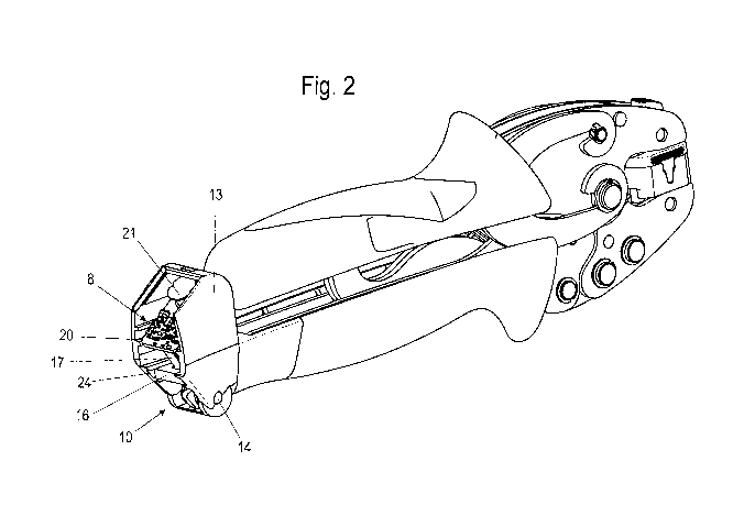
Figure 2 shows a perspective representation of the plier tool
according to Figure 1
with opened housing of the monitoring unit,
Figure 3 shows a cross-sectional view of the monitoring unit in the
non-actuated
state of the energy harvesting module, and
Figure 4 shows a cross-sectional representation of the monitoring
unit
corresponding to Figure 3 in the actuated state of the energy harvesting
module.
In the following description of the figures, terms such as upper, lower, left,
right, in the
front of, in the rear of, etc., refer exclusively to the selected exemplary
representation and
position of the plier tool, plier head, plier handle, of the monitoring unit,
of the energy harvesting
module and the like, in the respective figures. These terms should not be
understood to be
limiting, i.e., these relationships can change due to different work positions
or due to the mirror
symmetrical design or the like.
In Figures 1 and 2, an embodiment variant of a hand-actuatable plier tool
according to the
invention, in particular for processing cables, here in the form of crimping
pliers, is designated
overall with the reference numeral 1. The plier tool 1 has two plier handles
2, 3 and a plier head
6
CA 03056733 2019-09-16
for handling or processing a cable or electrical conductor. The plier handles
2, 3 are here
pivotable relative to one another via a pivot bearing 4.
In addition to the design of the plier tool 1 as crimping pliers shown here
for crimping a
cable or a conductor, it is also conceivable to design the plier tool 1 as
wire stripping pliers, a
cutting tool or the like.
Due to the plier handles 2, 3 being pressed together by the hand of a user,
the first plier
handle 3, which the lower one in Figures 1 and 2 and which is connected to a
lower clamping
jaw 6, is pivoted upward. In the process, a toggle mechanism is extended, so
that the clamping
jaw 6 is pivoted around the pivot bearing 4 in such a manner that the plier
mouth of the plier
head 5 of the plier tool 1 closes.
As can be seen moreover in Figures 1 and 2, an electronic monitoring unit 7 is
arranged
detachably fastened at the end of the lower plier handle 3 which is spaced
apart from the plier
head 5.
Here, the monitoring unit 7 is enclosed by a housing 13 and a housing cover 22
closing a
housing opening. On the housing cover 22, a closure nose 23 is formed, by
means of which the
housing cover 22 can be locked in the closed position thereof.
As shown in Figures 2, 3 and 4, the monitoring unit 7 has an electronic
circuit 8 and a
signal transmitter emitting actuation signals to the electronic circuit 8 when
the plier tool 1 is
actuated.
This signal transmitter has an energy harvesting module 9 which is used for
supplying
energy to the monitoring unit 7 and an actuation mechanism 10 activating the
signal transmitter.
It is also conceivable for the energy harvesting module 9 itself to have such
an actuation
mechanism.
7
CA 03056733 2019-09-16
In the embodiment variant represented here, the energy harvesting module 9 is
designed
as an inductive module which is coupled via an actuation lever 17 with an
actuation mechanism
10, for the conversion of mechanical energy into electrical energy.
Figure 3 here shows the monitoring unit 7 in the non-actuated state before the
plier
handles 2, 3 are pressed together, while Figure 4 shows the monitoring unit 7
with the actuation
mechanism 10 in the actuated state when the plier handles 2, 3 are pressed
together.
As represented in Figures 3 and 4, the actuation mechanism 10 has an actuation
tappet
18, which is firmly slidably mounted on the first of the plier handles, here
the lower plier handle
3, and is pushed into an inner space of the lower plier handle 3 when the
plier handles 2, 3 are
pressed together.
Here, the actuation tappet 18 is coupled with a first leg 11 of a leg spring
15. The
coupling here occurs via a clamping pin arranged in the actuation tappet 18
perpendicularly
relative to the movement axis of the actuation tappet 18, clamping pin which
carries the first leg
11 along with it during the movement in closing direction x. The leg spring 15
is rotatably
mounted on a pivot bearing 14 designed as a pin.
The pivot bearing 14 here extends perpendicularly to the closing direction x
in a direction
z in a recess provided for this purpose in the housing 13 of the monitoring
unit 7.
A second leg 12 of the leg spring 15 is secured on a slider 16 which is
slidably mounted,
here in longitudinal direction of extension y of the plier tool 1, in a
receiving groove 24 of the
housing 13 of the monitoring unit 7.
Thereby, a pivoting of the first leg 11 brings about a pivoting of the second
leg 12 and
thus a sliding of the slider 16.
8
CA 03056733 2019-09-16
The leg spring 15 of the actuation mechanism 10 is moreover used to damp
excess travel
of the actuation tappet, triggered, for example, by different crimping sizes
in the case of a plier
tool 1 designed as crimping pliers.
The leg spring 15 moreover simplifies the subsequent movement of the plier
handles 2, 3
with respect to one another in opening direction.
The slider 16 is secured on the actuation lever 17 of the energy harvesting
module 9, so
that the sliding of the slider 16 is accompanied by an activation of the
energy harvesting module
9 and converts the kinetic energy into electrical energy.
The energy harvesting module 9 is electrically connected to the electronic
circuit 8, in
particular to a circuit board 20 of the electronic circuit 8.
The movement of the slider 16 when the plier handles 2, 3 are pressed together
brings
about a movement of the actuation lever 17 of the energy harvesting module 9,
wherein the
energy harvesting module 9 converts this kinetic energy into electrical energy
and emits an
energy pulse to the electronic circuit 8, which starts a microprocessor of the
electronic circuit 8
and increases a counter memory by one increment, via the software stored in
the microprocessor.
Since, the electrical energy generated in the energy harvesting procedure is
usually much
greater than the energy needed by the processor, at least some of the
remaining electrical energy
is preferably used for activating a device for outputting information such as,
in particular, one or
more LEDs.
The electronic circuit 8 moreover preferably has a near-field communication
module
which can be activated via the fed-in energy of the energy harvesting module
9, in particular a
so-called NFC module, with a coil 21 used as an antenna, by means of which the
data present in
a data memory of the electronic circuit 8 can be wirelessly transmitted to a
mobile readout
9
CA 03056733 2019-09-16
device, in particular a Smartphone. The near-field communication (NFC) is
suitable here because
of the energy-independent mode of operation for reading out the data memory.
According to another embodiment variant, not represented further here, in
which the
monitoring unit 7 is designed as a wear calculation unit which can be
activated by actuating the
actuation mechanism 10 and the energy harvesting module 9, the monitoring unit
7 has a first
measuring unit coupled with the electronic circuit 8, for the acquisition of a
clamping force
exerted during the actuation of the plier tool 1.
Here, the measuring unit is preferably arranged in the area of the plier head
on the plier
tool 1. However, the arrangement of this first measuring unit at another site
of the plier tool 1 is
also conceivable.
As a result, the maximum force exerted by the hand of the user during an
actuation
procedure can be measured, which, in the electronic unit, enters into the
calculation of a useful
life value which can be stored in a data memory of the electronic circuit 8.
In the data memory, preferably a value for a maximum useful life of the plier
tool 1 is
stored, so that, by comparing this maximum useful life value with a current
use value of the plier
tool 1, which is calculated from the sum of the actuations performed and the
weighting thereof
via the force measurement of the individual actuation procedure, a
verification is enabled in
order to determine whether the useful life value has reached the value of the
maximum useful
life.
When the maximum useful life is reached, then, via the output unit, a
corresponding
signal can be output to the user.
In an additional embodiment variant of the plier tool 1 according to the
invention, the
monitoring unit 7 in addition has a second measuring unit coupled with the
electronic circuit 8,
CA 03056733 2019-09-16
which is used for the acquisition of an actuation distance covered during the
actuation of the plier
tool 1.
The measurement of the actuation distance together with a measurement of the
clamping
force applied enables the calculation of a quality inspection value, for
example, for the
qualitative inspection of a crimp, wherein the measured quality inspection
value or a quality
inspection curve calculated from multiple quality inspection values of this
type is compared with
a stored target value or target curve.
The second measuring unit here preferably consists of multiple individual
harvesting
modules connected one after the other, the voltage pulse of which is used
during the actuation of
the tool as a trigger for a certain actuation distance.
With each harvesting procedure, a force value is stored, which then is
converted into a
curve. The curve thus obtained can subsequently be compared with a preset
curve.
It is also conceivable that the energy harvesting module 9 itself is a
position sensor. For
this purpose, the energy harvesting module 9 generates energy pulses, for
example, in equidistant
sections of the actuation distance of the plier tool 1, with which the
electronic circuit can record
the clamping force values and distance points and combine them to form a
characteristic line.
The use of an individual additional energy harvesting module is also
conceivable.
In addition to the design of the energy harvesting module 9 as an inductive
module, it is
also conceivable to design the energy harvesting module 9 as a capacitive or
piezoelectric
module or as a module based on thermal energy or the like.
11
CA 03056733 2019-09-16
List of reference numerals
1 Plier tool
2 Upper plier handle
3 Lower plier handle
4 Pivot bearing
Plier head
6 Clamping jaw
7 Monitoring unit
8 Electronic circuit
9 Energy harvesting module
Actuation mechanism
11 First leg
12 Second leg
13 Housing
14 Pivot bearing
Leg spring
16 Slider
17 Actuation lever
18 Actuation tappet
19 Clamping pin
Circuit board
21 Antenna
12
CA 03056733 2019-09-16
22 Cover
23 Latching element
24 Receiving groove
x Closing direction
y Longitudinal direction of extension of the plier tool
z Depth of the plier tool
13