Note: Descriptions are shown in the official language in which they were submitted.
EXTENDING THE TRACKING VOLUME IN A PROBE TRACKING SYSTEM
CROSS-REFERENCE TO RELATED APPLICATIONS
This patent application claims the benefit of United
States Provisional Application Number 62/740,012 filed October
2, 2018 and United States Application Number 16/568,446 filed
September 12, 2019.
FIELD OF THE INVENTION
The present invention relates generally to invasive
medical procedures, and specifically to navigation of a probe
used in such procedures.
BACKGROUND
US Patent 8,456,182 to Bar-Tal et al., whose disclosure
is incorporated herein by reference, describes a method that
includes positioning body-electrodes in galvanic contact with
a body of a patient and positioning a mapping-tool, having a
mapping-electrode, in a plurality of regions in the body. The
method further includes tracking the mapping-tool at different
positions in each of the regions using a location-measuring
system, and for each region, generating a respective set of
calibration-currents between the body-electrodes and the
mapping-electrode at the different positions in the region. A
respective relation is derived for each region between the
respective set of the calibration-currents and the different
positions and is used in determining the location of an
investigation-tool in response to the different respective
relations and investigation-tool-currents.
1
CA 3057033 2019-09-27
SUMMARY OF THE INVENTION
There is provided, in accordance with some embodiments of
the present invention, a system including multiple
electrically-conductive channels and a processor. The
processor is configured to receive, over the electrically-
conductive channels, (i) respective first electric currents
from a probe, which is within a body of a patient, via a
plurality of first electrodes, which are attached to skin of
the patient at a region of the body, and (ii) a second electric
current from the probe via a second electrode, which is
attached to the skin and is connected to one of the channels.
The processor is further configured to ascertain respective
first electric-current values of the first electric currents
and a second electric-current value of the second electric
current, and to calculate a position of the probe between the
region and the second electrode, based on the first electric-
current values and the second electric-current value.
In some embodiments,
the region includes at least part of a thorax of the
patient,
the first electrodes are attached to the thorax, and
the second electrode is attached to a thigh of the
patient.
In some embodiments, the processor is configured to
calculate the position of the probe by:
calculating a normalized current-value IN = 12/IT, 12
being the second electric-current value and IT being a sum of
the first electric-current values and the second electric-
current value, and
calculating the position of the probe by applying a linear
function to IN.
In some embodiments, the processor is further configured
2
CA 3057033 2019-09-27
to learn the linear function prior to applying the linear
function, based on a plurality of initial electric currents
received from the probe via the first electrodes and the second
electrode.
In some embodiments, the processor is further configured
to:
ascertain that the position of the probe is within the
first region, and
in response to the ascertaining, disconnect the second
electrode from the one of the channels.
In some embodiments, the processor is further configured
to calculate a deflection angle of the probe, based on the
first electric-current values and the second electric-current
value.
There is further provided, in accordance with some
embodiments of the present invention, a system including a
plurality of first electrodes, configured to, while attached
to skin of a patient at a region of a body of the patient and
connected to different respective electrically-conductive
channels, receive respective first electric currents from a
probe disposed within the body, such that the first electric
currents are passed over the channels. The system further
includes a second electrode, configured to, while attached to
the skin, receive a second electric current from the probe.
The system further includes a switch, configured to connect
the second electrode to a particular one of the channels, while
the probe is between the region and the second electrode, such
that the second electric current is passed over the particular
one of the channels.
In some embodiments, the switch is configured to connect
the second electrode to the particular one of the channels by
short-circuiting the second electrode to a particular one of
the first electrodes.
3
CA 3057033 2019-09-27
In some embodiments, the switch is further configured to
connect the second electrode to an ablation-signal generator,
instead of to the particular one of the channels, while the
probe is in the region.
In some embodiments,
the switch is a first switch, and
the system further includes a second switch configured to
connect the second electrode to an ablation-signal generator
while the probe is in the region and the second electrode is
disconnected from the particular one of the channels.
In some embodiments,
the first switch is disposed internally to a console, and
the second switch is disposed internally to the ablation-
signal generator.
There is further provided, in accordance with some
embodiments of the present invention, a method including
receiving, over multiple electrically-conductive channels, (i)
respective first electric currents from a probe, which is
within a body of a patient, via a plurality of first electrodes,
which are attached to skin of the patient at a region of the
body, and (ii) a second electric current from the probe via a
second electrode, which is attached to the skin and is
connected to one of the channels. The method further includes
ascertaining respective first electric-current values of the
first electric currents and a second electric-current value of
the second electric current and calculating a position of the
probe between the region and the second electrode, based on
the first electric-current values and the second electric-
current value.
There is further provided, in accordance with some
embodiments of the present invention, a method including
receiving, by a plurality of first electrodes attached to skin
of a patient at a region of a body of the patient and connected
4
CA 3057033 2019-09-27
to different respective electrically-conductive channels,
respective first electric currents from a probe disposed within
the body, such that the first electric currents are passed over
the channels. The method further includes receiving, by a
second electrode attached to the skin, a second electric
current from the probe, and using a switch, connecting the
second electrode to a particular one of the channels, while
the probe is between the region and the second electrode, such
that the second electric current is passed over the particular
one of the channels.
In some embodiments,
the region includes at least part of a thorax of the
patient,
the first electrodes are attached to the thorax, and
the second electrode is attached to a thigh of the
patient.
There is further provided, in accordance with some
embodiments of the present invention, a computer software
product including a tangible non-transitory computer-readable
medium in which program instructions are stored. The
instructions, when read by a processor, cause the processor to
receive, over multiple electrically-conductive channels, (i)
respective first electric currents from a probe, which is
within a body of a patient, via a plurality of first electrodes,
which are attached to skin of the patient at a region of the
body, and (ii) a second electric current from the probe via a
second electrode, which is attached to the skin and is
connected to one of the channels. The instructions further
cause the processor to ascertain respective first electric-
current values of the first electric currents and a second
electric-current value of the second electric current, and to
calculate a position of the probe between the region and the
second electrode, based on the first electric-current values
5
CA 3057033 2019-09-27
and the second electric-current value.
BRIEF DESCRIPTION OF THE DRAWINGS
The present invention will be more fully understood from
the following detailed description of embodiments thereof,
taken together with the drawings, in which:
Fig. 1 is a schematic illustration of a probe tracking
system, according to an embodiment of the present invention;
Fig. 2 is a schematic illustration of a distal portion of
a probe tracked by the system, according to an embodiment of
the present invention;
Fig. 3 is a schematic diagram illustrating electrical
connections for a first modification of a tracking system,
according to an embodiment of the present invention;
Fig. 4 is a schematic diagram illustrating electrical
connections for a second modification of the tracking system,
according to an embodiment of the present invention;
Fig. 5 is a schematic diagram illustrating electrical
connections for a third modification of the tracking system,
according to an embodiment of the present invention;
Fig. 6 is a schematic illustration of an experimental
setup, Fig. 7 is a schematic illustration of a distal probe
used in the setup, and Fig. 8 is a schematic graph of results
from the setup, according to an embodiment of the present
invention;
Fig. 9 is a flowchart of steps performed in tracking a
probe in a patient, and Figs. 10 - 14 are diagrams illustrating
aspects of the flowchart, according to an embodiment of the
present invention.
6
CA 3057033 2019-09-27
DETAILED DESCRIPTION OF EMBODIMENTS
OVERVIEW
During some invasive cardiac procedures, a probe is
inserted into the body of a patient, e.g., via a left or right
femoral vein of the patient and is then advanced to the heart.
Upon reaching the heart, the probe may be used for mapping
and/or ablation.
In general, the probe may be well-tracked in the vicinity
of the heart using one or more known tracking systems, e.g., a
magnetic tracking system and/or an advanced current location
(ACL) system. However, these systems are typically configured
to track a probe only in a localized region, such as a volume
containing the heart, and generally do not provide good, or
even any, tracking outside the localized region. This may be
problematic during the advancement of the probe to the heart,
when the probe is relatively far from the heart. Alternative
tracking solutions include fluoroscopy and ultrasound;
however, fluoroscopy uses ionizing radiation, and ultrasound
probes have limited capability.
To address this challenge, embodiments of the present
invention augment an ACL system with an additional mapping
electrode, which is coupled to the patient's body near the
insertion point of the probe. The current received by the
additional mapping electrode is used to track the probe while
the probe is advanced to the heart. Embodiments of the present
invention may be used with any probe comprising at least two
electrodes separated by known distances, i.e., at least two
electrodes whose positions relative to each other are known.
More particularly, immediately following the insertion of
the probe into the patient, currents are injected into the
probe electrodes, and in response the additional mapping
electrode receives currents from the probe electrodes. It has
been determined that there is a linear relationship between
7
CA 3057033 2019-09-27
the received currents and the positions of the probe electrodes
along an axis running from the entry point of the probe to the
heart. Thus, provided that the relative electrode positions
are known, the received currents may be used to learn the
linear relationship. Subsequently to learning the linear
relationship, the linear relationship is used to track the
probe, in the one dimension referred to above, using the
currents received by the additional mapping electrode as the
probe is advanced through the vasculature of the patient.
SYSTEM DESCRIPTION
In the following description, like elements in the
drawings are identified by like numerals, and like elements
are differentiated as necessary by appending a letter to the
identifying numeral.
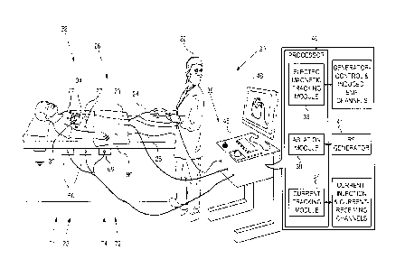
Reference is now made to Fig. 1, which is a schematic
illustration of a probe tracking system 20, and to Fig. 2,
which is a schematic illustration of a probe 32 tracked by the
system, according to an embodiment of the present invention.
In some embodiments, probe 32 is a distal portion of a catheter
24.
For simplicity and clarity, the following description,
except where otherwise stated, assumes a medical procedure is
performed by an operator 22 of system 20, herein assumed to be
a medical practitioner, wherein the operator inserts catheter
24 into a left or right femoral vein 26 of a patient 28. The
procedure may comprise, for example, investigation and/or
ablation of a heart 34 of the patient. Typically in the
procedure, the catheter is initially inserted into the patient
until probe 32 reaches a desired location in, or in proximity
to, heart 34 of the patient.
During the procedure, a plurality of patch electrodes 77,
also referred to herein as "skin patches," "patches," "skin
8
CA 3057033 2019-09-27
electrodes," or "electrodes," are attached to the skin of
patient 28 at a particular region of the patient's body
referred to herein as a mapping region 30. Typically, mapping
region 30 includes at least part of the patient's thorax, such
as at least part of the patient's heart, and electrodes 77 are
attached to skin of the thorax, such as the skin of the chest
and/or the back of the patient. By way of example, the present
description assumes six patches 77 attached to the skin of
patient 28 near the patient's heart.
System 20 comprises a processor 40, which performs the
functionality described herein by executing various modules,
each of which may comprise any suitable hardware and/or
software elements. The
modules include a current tracking
module 37, and may include, in addition, an electromagnetic
tracking module 36 and/or an ablation module 39. The functions
of the modules are described in more detail below. In general,
the function of a particular module may be said to be performed
by the module, or by the processor by executing the module.
Processor 40 is typically mounted in a console 46, which
comprises operating controls 38, typically including a pointing
device such as a mouse or trackball, that operator 22 uses to
interact with the processor. Results of the operations
performed by processor 40 are presented to the operator on a
display 48, which typically presents a visual representation
of the path taken by probe 32 in patient 28.
In general, processor 40 may be embodied as a single
processor, or as a cooperatively networked or clustered set of
processors. In some
embodiments, the functionality of
processor 40, as described herein, is implemented solely in
hardware, e.g., using one or more Application-Specific
Integrated Circuits (ASICs) or Field-Programmable Gate Arrays
(FPGAs). In other embodiments, the functionality of processor
is implemented at least partly in software. For example,
9
CA 3057033 2019-09-27
in some embodiments, processor 40 is embodied as a programmed
digital computing device comprising at least a central
processing unit (CPU) and random-access memory (RAM). Program
code, including software programs, and/or data are loaded into
the RAM for execution and processing by the CPU. The program
code and/or data may be downloaded to the processor in
electronic form, over a network, for example. Alternatively
or additionally, the program code and/or data may be provided
and/or stored on non-transitory tangible media, such as
magnetic, optical, or electronic memory. Such
program code
and/or data, when provided to the processor, produce a machine
or special-purpose computer, configured to perform the tasks
described herein.
For tracking the path of probe 32 in mapping region 30,
which contains heart 34, embodiments of the present invention
use a first, current based, tracking system 21, and may also
use a second, electromagnetic based, tracking system 23. Both
systems are described below, and, as is also described in more
detail below, in embodiments of the present invention the first
tracking system is modified to enable tracking of probe 32
outside region 30.
First tracking system 21 comprises a current measuring
tracking system, similar to that described in US Patent
8,456,182 to Bar-Tal et al., whose disclosure is incorporated
herein by reference. (An example of such a system is an ACL
system.) The CartoTM system produced by Biosense-Webster of 33
Technology Drive, Irvine, CA 92618 USA, also uses a current
measuring tracking system. The current measuring tracking
system is under control of current tracking module 37. Probe
32 has one or more probe electrodes 50A, 50B, 50C, ...,
generically termed probe electrodes 50 as illustrated in Fig.2.
In first tracking system 21, module 37 injects currents to
selected electrodes 50 being tracked. The currents are received
CA 3057033 2019-09-27
by patch electrodes 77 and are transferred to current tracking
module 37 over different respective electrically-conductive
channels. Thus, first tracking system 21 comprises electrodes
77 and module 37. (Although conductive cabling for patch
electrodes 77 and for other skin electrodes described herein
is present for each of the electrodes, for clarity cabling is
only shown in the figure for some of the electrodes.)
The currents between a given probe electrode 50 and skin
patches 77 vary according to the location of the probe
electrode, because, inter alia, of the dependency of the
impedance between the electrode and each patch on the distance
of the electrode from the patch. Module 37 measures the
respective currents received by patches 77. In response
thereto, module 37 calculates the position of each probe
electrode, and hence, the position of the probe, as further
described below. In response to calculating the position of
the probe, module 37 may generate an indication (e.g., a visual
indication on display 48) of the position of the probe.
As noted above, skin patches 77 are located at mapping
region 30, so that module 37 is able to determine the location
of a given electrode 50 within mapping region 30, from the
different patch currents, when the electrode is present in the
region.
In addition to skin patches 77, embodiments of the present
invention utilize another mapping electrode, referred to herein
as an "additional mapping electrode." In some embodiments,
the additional mapping electrode is an extra skin patch 70 that
is attached to the skin of patient 28, typically such that the
insertion point of the probe is between patch 70 and electrodes
77. For example, patch 70 may be attached to the skin of the
patient's thigh below (i.e., inferiorly to) the point at which
the probe is inserted into the patient's femoral vein.
Alternatively, for cases in which the probe is inserted into a
11
CA 3057033 2019-09-27
cephalic vein or another vein in the patient's arm, the patch
may be attached to the skin of the arm distally to the insertion
point, i.e., between the insertion point and the patient's
hand. (In some embodiments, a distance of at least 30 cm
separates patch 70 from the nearest electrode 77.) Similarly
to electrodes 77, extra skin patch 70 is configured to receive
electric currents from the probe while attached to the skin.
The manner in which these currents are used by first tracking
system 21 is described below.
When implemented, second tracking system 23 comprises an
electromagnetic tracking system, similar to that described in
US Patent 6,690,963 to Ben-Haim et al., whose disclosure is
incorporated herein by reference, and to that used in the
CartoTM system produced by Biosense-Webster. The
electromagnetic tracking system is under control of
electromagnetic tracking module 36. The electromagnetic
tracking system comprises a plurality of magnetic field
generators, herein assumed to comprise three sets of generators
66, each set comprising three orthogonal coils, so that the
plurality of generators comprises a total of nine coils.
Generators 66 are placed in known locations beneath patient
28, the known locations defining a frame of reference of the
generators. Module 36 controls, inter alia, the amplitude and
frequency of the alternating magnetic fields produced by the
generators.
The alternating magnetic fields interact with a coil
located in probe 32, so as to generate an alternating
electromotive force (EMS) in the coil, and the EMS is received
as a signal by tracking module 36. The module analyzes the
received signal, and from the analysis is able to determine a
location and an orientation of the probe coil in the defined
frame of reference.
Typically, the tracking by the first tracking system, or
12
CA 3057033 2019-09-27
by both of the tracking systems, is presented visually on
display 48, for example by incorporating an icon representing
the probe into an image of patient 28, as well as, optionally,
a representation of the path taken by the probe.
Ablation module 39 communicates with a radiofrequency (RE)
generator 41, which delivers RE power to a region of heart 34
that is selected by operator 22. Operator 22 selects the region
by positioning an ablation probe, with an ablation electrode,
at the region. While probe 32 and one of electrodes 50 may be
used as an ablation probe and an ablation electrode, for
clarity the description herein assumes use of a separate
ablation probe 74 having an ablation electrode 72. (Figs. 3,
4, and 5 illustrate probe 74 and electrode 72.)
The level of RE power, and the time period during which
the RE power is delivered, may be set by operator 22 using
controls 38. The current from the RE power delivered by
generator 41 to the patient through ablation electrode 72
returns to the generator via a return electrode 80, also herein
termed an RE indifferent electrode. Return electrode 80 is
attached to the skin of patient 28, typically to skin of the
patient's lower back. In some embodiments, as further described
below, return electrode 80 is used as an additional mapping
electrode, alternatively to extra patch 70.
Current tracking module 37 communicates with the
respective channels over which current is injected into
electrodes 50, along with the respective channels over which
current is received from the patch electrodes, as further
described below with reference to Fig. 3. Electromagnetic
tracking module 36 communicates with the channels over which
generator-control signals are sent to generators 66, along with
the channels over which induced EMFs are received from the coil
in probe 32.
As stated above, embodiments of the invention modify the
13
CA 3057033 2019-09-27
first tracking system to enable tracking of probe 32 outside
region 30. Each of the modifications described hereinbelow
connects the additional mapping electrode to a particular one
of the channels over which the patch currents are received,
while the probe is between mapping region 30 and the additional
mapping electrode. Based on the electric currents passed via
the additional mapping electrode over the particular one of
the channels, processor 40 calculates the position of the
probe.
First Modification
Fig. 3 is a schematic diagram illustrating electrical
connections for a first modification 21A of first tracking
system 21, according to an embodiment of the present invention.
In the figure, patient 28 is shown schematically as a circle
and an ellipse, and patch electrodes 77, attached to the
patient, have been identified as three patches 77A, 77B, 77C
on the front of the patient, and three patches 77D, 77E, and
77F on the patient's back.
Each patch 77 is connected to a different respective
electrically-conductive channel, such that each patch passes
its received electric currents over a different respective one
of the channels. By way of example, Fig. 3 shows six channels
C77A, C77B, 077C, 077D, C77E, and 077F, generically termed
channels C77. (Electrode 77A is connected to channel C77A,
electrode 77B to channel C77B, etc.) Each channel may comprise
any suitable electrically-conducting elements such as one or
more wires (or "lines"), ports, or sockets. Each channel may
be located externally and/or internally to console 46 (Fig.
1). By way of example, the figures herein assume that channels
077 belong to an electrical interface 35 in console 46.
While probe 32 and ablation probe 74 are not drawn to
scale, Fig. 3 assumes that ablation electrode 72 is within
region 30, and that probe 32 is outside the region. However,
14
CA 3057033 2019-09-27
system 21 and its modification do not depend on the presence
and functioning of probe 74.
In the first modification, system 21 is modified by
attaching extra patch electrode 70 to the skin of patient 28.
The extra patch is typically attached to the patient at a point
on the patient close to an expected path between an insertion
point of catheter 24 into patient 28 and region 30, and
typically below the insertion point. Thus, if the insertion
point is the left or the right femoral vein, and the probe path
is expected to continue along either of these veins, extra
patch 70 may be attached to the lower thigh of the patient.
Extra patch 70 is galvanically connected to one of
channels C77 by an electrically conducting line 71. For
example, line 71 may connect patch 70 to one of the channels
in lieu of one of patch electrodes 77 of system 21.
Alternatively, as shown in Fig. 3, line 71 may galvanically
connect (or "short-circuit") patch 70 to one of patch
electrodes 77 of system 21, herein by way of example assumed
to be electrode 77C.
In some embodiments, line 71 includes a switch 73, which
is configured to be closed, and hence maintain the connection
of electrode 70, at least while the probe is between mapping
region 30 and electrode 70. When provided, switch 73 may be
opened and closed by processor 40, or by operator 22, as
described below. For clarity, except where stated otherwise,
in the following description switch 73 is assumed to be absent.
It will be understood that first modification 21A
comprises electrodes 77 and extra patch electrode 70 connected
as described above. First modification 21A is able to track
any of electrodes 50 on probe 32, but for simplicity, except
where stated below, the description assumes that only electrode
50C is tracked.
The addition of extra patch electrode 70 creates a "split
CA 3057033 2019-09-27
patch" providing a single current, from the current injected
into electrode 500, to channel 077C. The single current is
derived from patches 70 and 77C, and depends, inter alia, on
the positioning of electrode 500 with respect to the two
patches. Hence, measuring this current provides an indication
of the position of electrode 500 outside region 30, as
described in detail below.
An advantage of first modification 21A is that the
additional tracking functionality provided by electrode 70 does
not require the addition of an electrically-conductive channel;
rather, electrode 70 is simply connected to an existing
channel.
Second Modification
Fig. 4 is a schematic diagram illustrating electrical
connections for a second modification 21B of first tracking
system 21, according to an embodiment of the present invention.
Apart from the differences described below, the operation of
modification 21B is generally similar to that of modification
21A (Fig. 3) and elements indicated by the same reference
numerals in both modifications are generally similar in
construction and in operation.
In contrast to modification 21A, there is no extra patch
electrode 70 in modification 21B. Rather, in modification 21B,
return electrode 80 functions as the additional mapping
electrode, by virtue of being connected to one of the channels
when the return electrode is not connected to RF generator 41.
For example, a switch 82, in a first configuration, may
galvanically connect indifferent electrode 80 to one of the
channels, e.g., by short-circuiting electrode 80 to one of
electrodes 77, herein assumed to be electrode 770, such that
the indifferent electrode is disconnected from the return of
RF generator 41. The first configuration is illustrated in Fig.
4.
16
CA 3057033 2019-09-27
In the first configuration, since the return of RF
generator 41 is disconnected from the indifferent electrode,
the RF generator is inoperative, and no ablation current is
transferred from ablation electrode 72. In addition, the
connected indifferent electrode and patch 77C act as a split
patch, providing a single current, from the current injected
into electrode 50C, to channel C77C. As for the first
embodiment, the single current depends, inter alia, on the
positioning of electrode 50C with respect to indifferent
electrode 80 and patch 77C, and measuring this current provides
an indication of the position of electrode 50C outside region
30.
In a second configuration of switch 82, the switch
connects indifferent electrode 80 to the return of RF generator
41, such that the indifferent electrode is disconnected from
channel C77C. In this configuration, RF generator 41 is
operative, and is able to deliver ablation current to electrode
72.
In general, switch 82 is in the first configuration when
the probe is between mapping region 30 and return electrode
80, and is in the second configuration when the probe is in
the mapping region. Switch 82 may be operated manually or by
processor 40.
An advantage of second modification 21B is that no extra
electrode is required. Moreover, as in the case of first
modification 21A, no additional electrically-conductive
channels, or changes to the RF generator, are required.
Third Modification
Fig. 5 is a schematic diagram illustrating electrical
connections for a third modification 210 of first tracking
system 21, according to an embodiment of the present invention.
Apart from the differences described below, the operation of
17
CA 3057033 2019-09-27
modification 210 is generally similar to that of modifications
21A and 21B (Figs. 3 and 4) and elements indicated by the same
reference numerals in the three modifications are generally
similar in construction and in operation.
Third modification 21C is similar to second modification
21B, in that additional tracking functionality is provided by
return electrode 80.
However, instead of a single switch
controlling the galvanic connection of return electrode 80,
two switches control this connection: a first switch 86
controls the connection to the channel, while a second switch
88 controls the connection to the RF generator.
In some embodiments, as shown in Fig. 5, first switch 86
is disposed internally to electrical interface 35 of the
console, and second switch 88, which may be referred to as an
"idling switch," is disposed internally to RF generator 41.
Hence, given that RF generator 41 is typically internal to the
console, both of the switches may be internal to the console.
In such embodiments, return electrode 80 is not connected to
patch 77C, and the switches are controlled by processor 40.
There are two states of operation of third modification
21C. In a first state, second switch 88 is open, so that the
RF generator does not provide any ablation power and so that
its return line is isolated from indifferent electrode 80. Also
in the first state, first switch 86 is closed so that there is
a galvanic connection between the indifferent electrode and
channel 0770. In this first state, indifferent electrode 80
effectively replaces patch 770, and because of the position of
the indifferent electrode, tracking of electrodes 50 may be
implemented between the indifferent electrode and region 30.
In a second state of operation of third modification 21C,
idling switch 88 is closed, so that ablation power may be
provided to electrode 72. Also in the second state, first
switch 86 is open so that there is no galvanic connection
18
CA 3057033 2019-09-27
between the indifferent electrode and channel 077C. In the
second state, tracking of electrodes 50 in region 30 may be
implemented, based on the currents received from the five
connected patches 77A, 77B, 77D, VVE, and 77F.
As in the case of second modification 21B, third
modification 21C does not require any extra electrode.
Moreover, the provision of internal switches, rather than
external switches, may simplify use of the system by the
operator.
INTRODUCTION TO TRACKING TECHNIQUES
As described above, while the probe is between mapping
region 30 and the additional mapping electrode, a plurality of
electric currents, including an electric current from the
additional mapping electrode, are received over channels C77.
After passing over the channels, the currents pass through
analog-to-digital (A/D) conversion circuitry, which is
typically located within console 46 (Fig. 1). The currents may
further pass through denoising circuitry, and/or any other
suitable circuitry. The digitized signals are received by
current tracking module 37 (Fig. 1), which is executed by
processor 40. In view of the above, it is noted that in the
context of the present application, including the claims, the
processor may be said to receive a signal via one of the patches
even though the processor does not receive the signal in its
raw form.
For each received current, current tracking module 37
ascertains (or "measures") the value of the current. As
described in detail below, based on the electric-current
values, the current tracking module calculates the position of
the probe between the mapping region and the additional mapping
electrode. In some embodiments, the processor also calculates
a deflection angle of the probe, based on the electric-current
values.
19
CA 3057033 2019-09-27
Typically, the position of the probe is calculated in one
dimension, along an axis running between the mapping region
and the region of the additional mapping electrode. For
example, for embodiments in which the mapping region is in the
patient's thorax and the additional mapping electrode is
attached to the patient's thigh, the processor may calculate
the position of probe along the patient's superior-inferior
axis.
Notwithstanding the above, in some embodiments, the
position of the probe is calculated in more than one dimension,
based on electric-current values from multiple additional
mapping electrodes. For
example, two extra skin patches 70
may be coupled to the patient's skin inferiorly to the
insertion point, one on the patient's right thigh and the other
on the patient's left thigh.
Subsequently, based on the
signals from the two extra skin patches, the position of the
probe may be calculated along the patient's superior-inferior
axis and also along the patient's lateral-medial axis. The
second extra skin patch may be galvanically connected to
another one of patches 77 (such as patch 77B) per first
modification 21A, or to an extra, dedicated channel C77.
As further described below, the processor typically
calculates the position of each probe electrode by (i)
calculating a normalized current-value IN = 12/IT, where, for
the current injected into the probe electrode, 12 is the value
of the current from the additional mapping electrode and IT
(or "'total") is sum of the values of the currents, and (ii)
applying a linear function to IN. The position of any of the
probe electrodes may then be taken as the position of the
probe; alternatively, the position of the probe may be defined
as the average of the respective probe-electrode positions.
By tracking the position of the probe, the processor may
CA 3057033 2019-09-27
ascertain when the position of the probe is within mapping
region 30. In response to ascertaining that the probe has
reached the mapping region, the processor may disconnect the
additional mapping electrode from channel C77C, e.g., by
controlling switch 73 (Fig. 3) or switch 82 (Fig. 4), or
switches 86 and 88 (Fig. 5).
Prior to applying the linear function, the processor
typically learns the linear function, based on initial electric
currents received from the probe via electrodes 77 and the
additional mapping electrode.
To help explain the theoretical basis for the tracking
techniques described herein, reference is now made to Figs. 6-
8. Fig. 6
is a schematic illustration of an experimental
setup, Fig. 7 is a schematic illustration of a distal probe
used in the setup, and Fig. 8 is a schematic graph of results
from the setup, according to an embodiment of the present
invention.
To validate the tracking performed by embodiments of the
invention, the inventors applied elements of second
modification 21B, in its first configuration, to a pig 128.
Thus, six patches 77 were attached to the skin of the pig; in
addition, indifferent electrode 80 was attached to the pig,
and was galvanically connected to patch 77C. Except as
otherwise stated, the experimental setup described herein
assumes that a probe 132, which is the distal portion of a
catheter generally similar to catheter 24, was inserted into
the pig 128.
To track probe 132 in the pig, a triple axis coil sensor
90 was incorporated in a known position into the probe, and
electromagnetic tracking system 23 was used to track the
position of the sensor. As described above, system 23 uses
magnetic generators 66 and electromagnetic tracking module 36
(Fig. 1), executed by processor 40, to induce a signal in
21
CA 3057033 2019-09-27
sensor 90, to analyze the signal, and to find the position of
the sensor from the analyzed signal. (The electromagnetic
tracking module communicates control signals to the generators
over generator-control channels 43.) The position was found in
a frame of reference 94 defined by generators 66, the frame of
reference having orthogonal axes where a positive y-axis is
assumed to be parallel to, and in the same direction as, the
longitudinal axis of the pig in the superior direction. (The
longitudinal axis of the pig is analogous to the superior-
inferior axis in a human patient.)
For the experimental setup, probe 132 was cylindrical,
and comprised five pairs of bipolar electrodes 92, i.e., ten
electrodes 92A1, 92A2, 92B1, 92B2, 92E1,
and 92E2, where
electrode 92A1 is the most distal electrode, and electrode 92E2
is the most proximal. The positions and spacings of the
electrodes along probe 132 were measured, and this spacing
remained constant during the experiment.
Initially, an electrically-insulative sheath 96 was
inserted several millimeters into a femoral vein of the pig.
Probe 132 was inserted into the sheath, and current tracking
module 37 (Fig. 1), executed by processor 40, injected
respective currents into the ten electrodes 92 of the probe.
During the experiment, current tracking module 37 measured
the current received by channel C77C, Ic77c, from patch 77C
and indifferent electrode 80. From this measured current, the
current received by indifferent electrode 80 was estimated, as
explained below:
Module 37 measured the five currents from patches 77A,
77B, 77D, 77E, and 77F, received by their respective channels
in the module, to find a total current for these patches. The
module then added the current received by channel C77C to find
a total current received by module 37, Itotal. A normalized
22
CA 3057033 2019-09-27
current to channel C77C was then calculated as the ratio IN:
'C77C
IN (1)
'total
Typically, for a probe in region 30, the current in
channel C77C (i.e., the current from patch 77C) is
substantially equal to each of the currents from patches 77A,
1
778, 77D, 77E, and 77F, and so IN is approximately ;, i.e.,
approximately 17%. Any value above this gives an estimate of
the normalized current from the indifferent electrode.
Fig. 8 is a schematic graph of normalized current, IN,
for each of the ten electrodes 92 vs. the measured position of
sensor 90, as probe 132 is moved though the femoral vein of
pig 128. As stated above, the position of sensor 90 was measured
using electromagnetic tracking module 36, and the position
measured was the y-value of the sensor.
The graph is divided into two sections: a first region A,
which corresponds to a state when all or some of electrodes 92
were within the sheath, and a second region B, which
corresponds to a state when all of the electrodes had exited
from the sheath.
The graph illustrates that as the probe approached the
distal end of the sheath, the normalized currents from each
electrode 92 increased to a maximum current, which is
approximately 50%. On exit from the sheath, each normalized
current decreased from the maximum current.
As is apparent from the graph, in region B the normalized
currents from electrodes 92 decreased monotonically as the
probe moved away from the additional mapping electrode. As is
also apparent from the graph, the change of normalized current
with respect to the measured y-value is linear.
Thus, each line of the graphs may be represented by an
23
CA 3057033 2019-09-27
equation:
IN =m=Y+ b (2)
where m is the slope of the IN vs. y graph, and
b is the vertical axis intercept of the IN vs. y graph.
While the experiment described above was performed for a
configuration based on the second modification described above,
the inventors have verified that the linear change of current
with respect to y-value holds for the other modifications
described herein.
TRACKING THE PROBE
The experiment described above demonstrates that the
normalized current varies linearly with the position of the
probe along the superior-inferior axis. As described below,
processor 40 is configured to learn this linear relationship,
even without using an electromagnetic tracking system, and to
then use the learned linear relationship to track the probe.
By way of introduction, it is noted that equation (2) may
be rewritten:
IN¨b
Y --
M
or y= NI IN 4- B ( 3)
where M is a parameter of equation (3) corresponding to
the slope of a y vs. IN graph, and
B is a parameter of equation (3) corresponding to the
vertical axis intercept of the y vs. IN graph.
Hence, as is explained below with reference to the
flowchart of Fig. 9, processor 40 may formulate an equation,
in the form of equation (3), to calculate values of y from
measured values of IN, for each of the electrodes on probe 32.
24
CA 3057033 2019-09-27
It is noted that equation (3) is a linear relationship
between a y-position and a normalized current for each
electrode. In the disclosure and in the claims, if a linear
relationship exists between a first variable such as the y-
position, and a second variable such as the normalized current,
then there is a constant ratio between a change of the first
variable and the corresponding change of the second variable.
For example, equation (3) has a constant ratio M.
Fig. 9 is a flowchart of steps performed in tracking a
probe in a patient, and Figs. 10 - 14 are diagrams illustrating
aspects of the flowchart, according to an embodiment of the
present invention. For clarity the flowchart assumes that the
configuration of first modification 21A (Fig. 3) is
implemented, with probe 32 of catheter 24 being inserted into
patient 28. Except as otherwise stated below, first
modification 21A is assumed not to Include switch 73, so that
patch 70 is always galvanically connected to patch 77C. By way
of example, probe 32 is assumed to comprise three electrodes
50A, 50B, 50C, with electrode 50A being the most distal
electrode and electrode 50C being the most proximal electrode.
However, it will be understood that in embodiments of the
present invention the probe may have two, or more than three,
electrodes.
Probe 32 is assumed to be cylindrical, and prior to
insertion into patient 28 the distances between electrodes 50A
and 50B, and between electrodes 50B and 50C, are measured and
recorded as DAB and DBc, as shown in Fig. 11. A distance between
the most proximal and most distal electrodes, (DAB + DBc), AD,
is also recorded. In addition, a value for a threshold current,
'thresh, the significance of which is described below, is input
to processor 40. In one embodiment, 'thresh is set at 450pA,
for a procedure wherein a current of 500pA is injected into
each electrode 50. However, those having skill in the art will
CA 3057033 2019-09-27
be able to formulate other suitable values for 'thresh without
undue experimentation. As is explained below, in implementing
the steps of the flowchart, the processor calculates values
for M and B in equation (3).
In a first step 100, operator 22 inserts a short sheath
into a femoral vein of patient 28, and then inserts probe 32
into the sheath. Processor 40 then begins measuring the
currents received in channels C77 and calculates the normalized
currents for each of electrodes 50A, 50B, and 50C. Initially,
the normalized currents increase, as is illustrated in region
A of the graph of Fig. 8.
In an exiting step 102, the processor registers when the
currents, totaled for all patches 77, from all of electrodes
50A, 50B, and 50C, have become greater than threshold current
'thresh- At this point, the processor assumes that all the
probe electrodes have exited the sheath. An indication that
this point has been reached may be provided to operator 22,
for example by the processor positioning a marker 120 on a
generic figure 124 of a patient on display 48, as is illustrated
in Fig. 10.
Upon the total current exceeding 'thresh' the processor
records the normalized current values for the most distal
electrode 50A, 'distal' and for the most proximal electrode
50C, I proximal- The processor also records the normalized
current values for any intermediate electrodes, in this case
electrode 50B, herein termed I50B. At this point, the probe is
assumed to be aligned with the y-axis, the origin of which,
for simplicity, may be placed at the most proximal electrode
(which is adjacent to the distal end of the sheath), as is
illustrated in Fig. 11.
The processor then calculates a value for the slope M in
equation (3) using equation (4):
26
CA 3057033 2019-09-27
AD
M= _____________________________________________________ (4)
Idistal-Iproximal
where
AD is the distance between the most distal electrode 50
and the most proximal electrode 50.
Using the value of parameter M from equation (4),
processor solves for the value of B that best satisfies the
three equations in Table I below. Alternatively, the processor
may solve for B based on a subset of the equations in Table I.
Table I
Electrode Equation
50C Ysoc = 0 = M =
INsoc B
50B Y5OB = DBC = M IN150B B
50A Y50A = AD = M = INsoA B
In a continue tracking step 104, processor 40 continually
measures values of IN50c, IN50B, and IN50A, as operator 22
pushes probe 32 further into the femoral vein. From the
measured values at any given instance of time t during step
104, the processor calculates values of y50c, y5013, and Y50A --
the respective y-positions of electrodes 50 - using equation
(3) with the values of M and B derived as described above. (The
y-position of each electrode indicates the distance of the
electrode from the sheath.) The processor averages the values
mean
of Y50C, y50B, and y50A to find a mean y position Y (t) for
the probe at the time selected, as given by equation (5):
YsoCi-YsoBA-YsoA
Yrnean(t) 3 (5)
An indication that the position of the probe has reached
a value of y(t) at the time selected may be provided to
operator 22 by the processor moving marker 120 on the generic
27
CA 3057033 2019-09-27
figure of the patient, to a position corresponding to Ymean(t),
as illustrated in Fig. 12.
While for clarity the description herein assumes that
processor 40 uses linear relationships in the form of
equations, those having skill in the art will appreciate that
the processor may use other forms of linear relationships, such
as a look-up table, and all such linear relationships are
assumed to be comprised within the scope of the present
invention. Thus, for example, given a normalized current, the
processor may look up the corresponding y-position in a look-
up table, rather than explicitly calculating the y-position
using equation (3). The equation, look-up table, or other
representation of the linear relationship may be referred to
as a "linear function."
Also in step 104, the processor continually checks the
deflection angle (or "deflection") 0 of the probe relative to
the y-axis defined in step 102, as illustrated in Fig. 13. The
processor finds at any given time t a distance AD(t), parallel
to the y-axis, between the most proximal and most distal
electrodes, as given by equation (6):
ADM = y50C -- 3/50A (6)
The processor then compares this distance with the value
of AD (known from the initial measurements on electrodes 50C
and 50A) to find deflection 0, according to equation (7):
AD(t)
0 = arccos ____________________________________ (7)
AD
In a first comparison step 106, the processor checks if
the deflection 0 exceeds a preset threshold value, which in
some embodiments is set at 450. If the preset value is exceeded,
the processor may issue a warning, in a warning step 108, to
operator 22 that probe 32 may have deviated from the femoral
28
CA 3057033 2019-09-27
vein (for example, by the probe having been inadvertently
advanced into a vein communicating with the femoral vein). In
one embodiment, the warning comprises a visual notification.
For example, the processor may replace marker 120 with a
different marker 130, as illustrated in Fig. 14. Upon receipt
of the warning, operator 22 may manipulate the probe so that
deflection 0 does not exceed the preset value. Typically, after
issuing a warning, the processor repeatedly performs first
comparison step 106, and issues subsequent warnings (e.g., by
continuing to show marker 130), until the necessary correction
to the probe orientation has been made.
Upon first comparison step 106 returning negative, i.e.,
upon deflection 0 not exceeding the preset value, control of
the flowchart continues to a second comparison step 112,
wherein the processor checks if probe 32 is within region 30
(Fig. 1). The check if probe 32 is within region 30 may be by
any suitable method, such as, but not limited to, observing
the currents on patch electrodes 77 relative to that on patch
77C (e.g., observing that the difference between the current
on patch 77C and one of the other patches is less than a
predefined threshold), and/or detecting that
electrocardiograph (ECG) signals are present on one or more of
electrodes 50 (assuming that mapping region 30 includes the
heart), and/or using magnetic location if probe 32 has a
magnetic sensor.
If second comparison step 112 returns negative, i.e.,
probe 32 is not in heart mapping region 30, control for the
flowchart returns to step 104.
If second comparison step 112 returns positive, i.e.,
probe 32 is within region 30, an indication may be presented
to operator 22 on display 48 that the probe is in the heart
mapping region. In addition, in a final step 116 of the
flowchart, processor 40 may stop tracking the (one-dimensional)
29
CA 3057033 2019-09-27
y-position of the probe, and instead use the currents from all
electrode patches 77 to track the (three-dimensional) position
of the probe, using current based tracking system 21.
If switch 73 is present in line 71 (Fig. 3), then it is
closed during steps 100 - 112, and is opened when control
passes to final step 116. The closing and opening of switch 73
may be implemented manually by operator 22, and/or
automatically by processor 40.
While the description above for the flowchart of Fig. 9
assumes for clarity that modification 21A is implemented to
enable tracking of a probe, those having ordinary skill in the
art will be able to modify the description, mutatis mutandis,
if modifications 21B or 210 are implemented for tracking of
the probe.
It will be appreciated by persons skilled in the art that
the present invention is not limited to what has been
particularly shown and described hereinabove.
Rather, the
scope of embodiments of the present invention includes both
combinations and subcombinations of the various features
described hereinabove, as well as variations and modifications
thereof that are not in the prior art, which would occur to
persons skilled in the art upon reading the foregoing
description.
Documents incorporated by reference in the
present patent application are to be considered an integral
part of the application except that to the extent any terms
are defined in these incorporated documents in a manner that
conflicts with the definitions made explicitly or implicitly
in the present specification, only the definitions in the
present specification should be considered.
CA 3057033 2019-09-27