Language selection

Search

Patent 3058094 Summary

Third-party information liability

Some of the information on this Web page has been provided by external sources. The Government of Canada is not responsible for the accuracy, reliability or currency of the information supplied by external sources. Users wishing to rely upon this information should consult directly with the source of the information. Content provided by external sources is not subject to official languages, privacy and accessibility requirements.

Claims and Abstract availability

Any discrepancies in the text and image of the Claims and Abstract are due to differing posting times. Text of the Claims and Abstract are posted:

  • At the time the application is open to public inspection;
  • At the time of issue of the patent (grant).
(12) Patent Application: (11) CA 3058094
(54) English Title: JIB ASSEMBLY
(54) French Title: ENSEMBLE DE FLECHE
Status: Deemed Abandoned and Beyond the Period of Reinstatement - Pending Response to Notice of Disregarded Communication
Bibliographic Data
(51) International Patent Classification (IPC):
  • E02F 9/14 (2006.01)
  • E02F 3/28 (2006.01)
(72) Inventors :
  • GROHN, PEKKA (Finland)
  • LAAKKONEN, PENTTI (Finland)
  • HUOVINEN, SIMO (Finland)
(73) Owners :
  • MANTSINEN GROUP LTD OY
(71) Applicants :
  • MANTSINEN GROUP LTD OY (Finland)
(74) Agent: NORTON ROSE FULBRIGHT CANADA LLP/S.E.N.C.R.L., S.R.L.
(74) Associate agent:
(45) Issued:
(86) PCT Filing Date: 2018-01-11
(87) Open to Public Inspection: 2018-08-02
Availability of licence: N/A
Dedicated to the Public: N/A
(25) Language of filing: English

Patent Cooperation Treaty (PCT): Yes
(86) PCT Filing Number: PCT/FI2018/050019
(87) International Publication Number: WO 2018138409
(85) National Entry: 2019-09-26

(30) Application Priority Data:
Application No. Country/Territory Date
20175062 (Finland) 2017-01-25

Abstracts

English Abstract

The disclosure relates to a jib assembly (1) comprising a support (11); a jib (12) attached pivotally to the support (11) for pivotal movement of the jib (12) in relation to the support (11) about a horizontal axis; a first linear hydraulic actuator (13) attached to the support (11) for regulating pivotal movement of the jib (12) and for maintaining the jib (12) in a specific position relative to the support (11); a lever arm (14) attached unrotatably to the jib (12); and a draw member (15) attached to the lever arm (14) and to the jib (12); wherein the first linear hydraulic actuator (13) is attached to the lever arm (14), and the lever arm (14) is arranged to extend in the direction above the jib (12).


French Abstract

L'invention concerne un ensemble de flèche (1) comprenant un support (11); une flèche (12) fixée pivotante au support (11) pour un mouvement de pivotement de la flèche (12) par rapport au support (11) autour d'un axe horizontal; un premier actionneur hydraulique linéaire (13) fixé au support (11) pour ajuster le mouvement de pivotement de la flèche (12) et pour maintenir la flèche (12) dans une position spécifique par rapport au support (11); un bras de levier (14) fixé de manière non rotative à la flèche (12); et un élément de traction (15) fixé au bras de levier (14) et à la flèche (12); le premier actionneur hydraulique linéaire (13) étant fixé au bras de levier (14), et le bras de levier (14) étant agencé pour s'étendre dans la direction au-dessus de la flèche (12).

Claims

Note: Claims are shown in the official language in which they were submitted.

CLAIMS
1. A jib assembly (1) comprising
--- a support (11);
--- a jib (12) attached pivotally to the support (11) for pivotal movement of
the jib (12)
in relation to the support (11) about a horizontal axis; and
--- a first linear hydraulic actuator (13) attached to the support (11) for
regulating
pivotal movement of the jib (12) and for maintaining the jib (12) in a
specific
position relative to the support (11);
characterized in that,
the jib assembly (1) further comprises
--- a lever arm (14) attached unrotatably to the jib (12); and
--- a draw member (15) attached unrotatably to the lever arm (14) and to the
jib (12);
wherein
the first linear hydraulic actuator (13) is connected to the draw member (15)
so that a
force generated by the first linear hydraulic actuator (13) is transmitted to
the draw
member (15);
the first linear hydraulic actuator (13) and the draw member (15) are
supported by the
lever arm (14); and
the lever arm (14) is arranged to extend in the direction above the jib (12).
2. A jib assembly (1) according to claim 1, characterized in that the draw
member (15)
is a drawbar.
3. A jib assembly (1) according to claim 1, characterized in that the draw
member (15)
is a cable.
4. A jib assembly (1) according to any one of the preceding claims,
characterized in that
the jib assembly (1) comprises a second linear hydraulic actuator (16)
comprising a
first end (161) and a second end (162), the first end (161) of the second
linear
hydraulic actuator (16) being attached to the support (11) and the second end
(162)
of the second linear hydraulic actuator (16) being attached to the jib (12).
5. An excavator comprising a jib assembly (1) according to any one of
claims 1 to 4.

6
6. A material handler comprising a jib assembly (1) according to any one of
claims 1 to
4.
7. Use of the jib assembly (1) according to any one of claims 1 to 4 in an
excavator.
8. Use of the jib assembly (1) according to any one of claims 1 to 4 in a
material handler.

Description

Note: Descriptions are shown in the official language in which they were submitted.


CA 03058094 2019-09-26
WO 2018/138409
PCT/F12018/050019
1
JIB ASSEMBLY
FIELD OF THE DISCLOSURE
The present disclosure relates to a jib assembly, for example for an excavator
or material
handler.
BACKGROUND OF THE DISCLOSURE
Document GB 1432124 A discloses jib assemblies, where potential energy is
transferred
between a jib, pivoted at on a support, and an accumulator through fluid
passing via a duct
between a chamber in a hydraulic jack and the accumulator as the jib is luffed
by
conventional means. The jack may be replaced by a jack having a rotary piston.
A problem with the known assembly is that because the pulling and pushing
force of two
hydraulic cylinders, i.e. the hydraulic jacks, is applied to a small area at
the base of the jib,
it causes a great bending moment and a concentration of stress to the jib,
which results in
fatigue of the structure over time. To overcome this, the jib structure must
be made rugged
enough, i.e. heavy, which reduces the lifting capacity and energy economy.
Another problem relates to attaching the hydraulic cylinder directly to the
support and to
the jib, limiting the geometry of the structure. This results in generation of
a certain lifting
moment at each lifting angle of the jib, which may not be practical for the
need. The
geometry and the required raise of the jib forces to use a hydraulic cylinder
of a certain
length. Because the lifting moment cannot be directed practically, the piston
travel of the
hydraulic cylinder must be unnecessary long, which generates lifting moment to
areas
where it is not needed. In high angles of the jib, extra lifting moment is a
hindrance because
it requires pressing the jib downwards to get the jib down, when there is no
load. The
stroke, i.e. the volume, of the hydraulic cylinder on the other hand is
directly proportional
to the volume of an accumulator when a certain force and pressure level is
desired to be
maintained. The volume of the accumulator is expensive for example because of
the
regulation relating to pressure vessels.
The aforementioned problems are especially present in excavators requiring
wide
movements and long jibs.
BRIEF DESCRIPTION OF THE DISCLOSURE
An object of the present disclosure is to provide a jib assembly to solve the
above
problems.

CA 03058094 2019-09-26
WO 2018/138409
PCT/F12018/050019
2
The object of the disclosure is achieved by a jib assembly which is
characterized by what
is stated in the independent claims. The preferred embodiments of the
disclosure are
disclosed in the dependent claims.
The disclosure is based on the idea of providing a jib assembly comprising a
jib, a linear
hydraulic actuator for regulating pivotal movement of the jib and for
maintaining the jib in
a specific position, a lever arm attached to the jib and a draw member
attached to the lever
arm and to the jib, wherein the linear hydraulic actuator is attached to the
lever arm and
the lever arm is arranged to extend in the direction above the jib.
An advantage of jib arrangement of the disclosure is that when the jib is
positioned
essentially vertically, the required lifting moment is reduced significantly.
In this situation,
the current solution provides small lifting moment and a very small change in
the length of
the hydraulic cylinder in relation to the angular change. This results in
ability to size the
hydraulic cylinder and the accumulator practically.
Another advantage of the jib arrangement of the disclosure is that because a
part of the
lifting moment is transmitted by the draw member to a further point of the
jib, for example
to the end of the jib, it provides the jib with a smaller bending moment.
Because of the
geometry, only a small component of force is brought to stressed area of the
jib by the
lever arm. Additionally, this component of force resists the normal fatiguing
bending in the
positions of the jib causing most stress.
BRIEF DESCRIPTION OF THE DRAWINGS
In the following the disclosure will be described in greater detail by means
of preferred
embodiments with reference to the accompanying drawing, in which
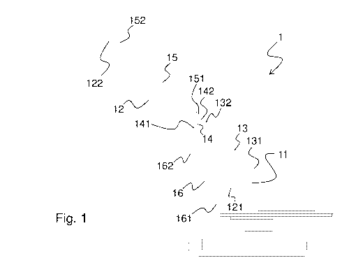
Figure 1 is a schematic view of a jib assembly according to an embodiment of
the
disclosure.
DETAILED DESCRIPTION OF THE DISCLOSURE
The disclosure relates to a jib assembly 1. The jib assembly 1 comprises a
support 11.
The support 11 is for example formed by a frame of an excavator.
The jib assembly 1 comprises a jib 12. For example, the jib is arranged to
support the arm
of the excavator connected to the bucket (not shown in the figure). The jib 12
is attached
pivotally to the support 11 for pivotal movement of the jib 12 in relation to
the support 11
about a horizontal axis. For example, the jib 12 comprises a first end 121 and
a second
end 122, and the first end 121 of the jib 12 is attached to the support 11.

CA 03058094 2019-09-26
WO 2018/138409
PCT/F12018/050019
3
The jib assembly 1 comprises a lever arm 14. The lever arm 14 is attached
essentially
unrotatably to the jib 12. For example, the lever arm comprises a first end
141 and a
second end 142, and the first end 141 of the lever arm 14 is attached to the
jib 12. The
lever arm 14 is arranged to extend in the direction above the jib 12. For
example, the lever
arm 14 is bolted or welded to the jib 12. Alternatively, the lever arm 14 is
attached to the
jib by pins (not shown in the figure) According to an embodiment, the lever
arm 14 is
integral with the jib 12.
The jib assembly 1 comprises a first linear hydraulic actuator 13 for
regulating pivotal
movement of the jib 12 and for maintaining the jib 12 in a specific position
relative to the
support 11. For example, the first linear hydraulic actuator 13 comprises a
hydraulic
cylinder. According to an embodiment, the jib assembly 1 comprises a plurality
of the first
linear hydraulic actuators 13. The first linear hydraulic actuator 13 is
attached to the
support 11. For example, the first linear hydraulic actuator 13 comprises a
first end 131
and a second end 132, and the first end 131 of the first linear hydraulic
actuator 13 is
attached to the support 11. The first linear hydraulic actuator 13 is
supported by the lever
arm 14. For example, the second end 132 of the first linear hydraulic actuator
13 is
connected to the second 142 end of the lever arm 14.
The jib assembly 1 comprises a draw member 15. The draw member 15 is attached
essentially unrotatably to the lever arm 14 and to the jib 12. The draw member
15 is
attached to the jib 12 at a position away from the support 11 in relation to
the lever arm
14. For example, the draw member 15 comprises a first end 151 and a second end
152,
and the first end 151 of the draw member 15 is attached essentially
unrotatably to the
second end 142 of the lever arm 14 and the second end 152 of the draw member
15 is
attached essentially unrotatably to the second end 122 of the jib 12.
According to an
embodiment, the draw member 15 is a drawbar. According to an alternative
embodiment,
the draw member 15 is a cable. The first linear hydraulic actuator 13 is
connected to the
draw member 15 so that a force generated by the first linear hydraulic
actuator 13 is
transmitted to the draw member 15. The draw member 15 is supported by the
lever arm
14. Preferably the lever arm 14 has a length and it is attached to the jib 12
at a location
that allow a straight draw member 15 to be connected to the lever arm 14 and
to the second
end 122 of the jib.
According to an embodiment, the jib assembly 1 comprises a second linear
hydraulic
actuator 16. The purpose of the second linear hydraulic actuator 16 is to aid
the first linear
hydraulic actuator 13 with the pivotal movement of the jib 12. For example,
the second
linear hydraulic actuator 16 comprises a hydraulic cylinder. The second linear
hydraulic

CA 03058094 2019-09-26
WO 2018/138409 PCT/F12018/050019
4
actuator 16 is attached to the support 11 and to the jib 12. For example, the
second linear
hydraulic actuator 16 comprises a first end 161 and a second end 162, and the
first end
161 of the second linear hydraulic actuator 16 is attached to the support 11
and the second
end 162 of the second linear hydraulic actuator 16 is attached to the jib 12.
The disclosure relates also to an excavator comprising a jib assembly 1 as
described
above.
The disclosure relates also to a material handler comprising a jib assembly 1
as described
above.
The disclosure relates also to use of the jib assembly 1 as described above in
an
excavator.
The disclosure relates also to use of the jib assembly 1 as described above in
a material
handler.

Representative Drawing
A single figure which represents the drawing illustrating the invention.
Administrative Status

2024-08-01:As part of the Next Generation Patents (NGP) transition, the Canadian Patents Database (CPD) now contains a more detailed Event History, which replicates the Event Log of our new back-office solution.

Please note that "Inactive:" events refers to events no longer in use in our new back-office solution.

For a clearer understanding of the status of the application/patent presented on this page, the site Disclaimer , as well as the definitions for Patent , Event History , Maintenance Fee  and Payment History  should be consulted.

Event History

Description Date
Application Not Reinstated by Deadline 2024-04-24
Inactive: Dead - RFE never made 2024-04-24
Letter Sent 2024-01-11
Deemed Abandoned - Failure to Respond to Maintenance Fee Notice 2023-07-11
Deemed Abandoned - Failure to Respond to a Request for Examination Notice 2023-04-24
Letter Sent 2023-01-11
Common Representative Appointed 2020-11-07
Common Representative Appointed 2019-10-30
Inactive: Cover page published 2019-10-22
Inactive: Notice - National entry - No RFE 2019-10-19
Application Received - PCT 2019-10-15
Inactive: IPC assigned 2019-10-15
Inactive: First IPC assigned 2019-10-15
National Entry Requirements Determined Compliant 2019-09-26
Application Published (Open to Public Inspection) 2018-08-02

Abandonment History

Abandonment Date Reason Reinstatement Date
2023-07-11
2023-04-24

Maintenance Fee

The last payment was received on 2022-01-05

Note : If the full payment has not been received on or before the date indicated, a further fee may be required which may be one of the following

  • the reinstatement fee;
  • the late payment fee; or
  • additional fee to reverse deemed expiry.

Please refer to the CIPO Patent Fees web page to see all current fee amounts.

Fee History

Fee Type Anniversary Year Due Date Paid Date
Basic national fee - standard 2019-09-26
MF (application, 2nd anniv.) - standard 02 2020-01-13 2019-09-26
Reinstatement (national entry) 2019-09-26
MF (application, 3rd anniv.) - standard 03 2021-01-11 2020-12-11
MF (application, 4th anniv.) - standard 04 2022-01-11 2022-01-05
Owners on Record

Note: Records showing the ownership history in alphabetical order.

Current Owners on Record
MANTSINEN GROUP LTD OY
Past Owners on Record
PEKKA GROHN
PENTTI LAAKKONEN
SIMO HUOVINEN
Past Owners that do not appear in the "Owners on Record" listing will appear in other documentation within the application.
Documents

To view selected files, please enter reCAPTCHA code :


To view images, click a link in the Document Description column. To download the documents, select one or more checkboxes in the first column and then click the "Download Selected in PDF format (Zip Archive)" or the "Download Selected as Single PDF" button.

List of published and non-published patent-specific documents on the CPD .

If you have any difficulty accessing content, you can call the Client Service Centre at 1-866-997-1936 or send them an e-mail at CIPO Client Service Centre.


Document
Description 
Date
(yyyy-mm-dd) 
Number of pages   Size of Image (KB) 
Claims 2019-09-26 2 42
Drawings 2019-09-26 1 13
Abstract 2019-09-26 2 66
Description 2019-09-26 4 172
Representative drawing 2019-09-26 1 12
Cover Page 2019-10-22 1 40
Notice of National Entry 2019-10-19 1 202
Commissioner's Notice: Request for Examination Not Made 2023-02-22 1 519
Commissioner's Notice - Maintenance Fee for a Patent Application Not Paid 2023-02-22 1 551
Courtesy - Abandonment Letter (Request for Examination) 2023-06-05 1 550
Courtesy - Abandonment Letter (Maintenance Fee) 2023-08-22 1 550
Commissioner's Notice - Maintenance Fee for a Patent Application Not Paid 2024-02-22 1 552
National entry request 2019-09-26 5 170
International search report 2019-09-26 8 261