Note: Descriptions are shown in the official language in which they were submitted.
CA 03058374 2019-09-27
DESCRIPTION
CARBON MATERIAL FOR USE AS CATALYST CARRIER OF POLYMER
ELECTROLYTE FUEL CELL AND METHOD OF PRODUCING THE SAME
Technical Field
[0001] The present disclosure relates to a carbon material for use as a
catalyst carrier of a
polymer electrolyte fuel cell and a method of producing the same.
Background Art
[0002] In recent years, attention has been paid to a polymer electrolyte fuel
cell which can
operate at a low temperature of 100 C or less, and development and
commercialization
thereof have been progressed as a driving power source for a vehicle, and a
stationary power
generation device. The basic structure (unit cell) of a general polymer
electrolyte fuel cell is
constituted with a membrane electrode assembly (MEA) constituted with a proton
conductive
electrolyte membrane, and on each side thereof a catalyst layer to function as
an anode or a
cathode sandwiching the electrolyte membrane; and gas diffusion layers
disposed on the
outside of the respective catalyst layers sandwiching the membrane electrode
assembly; as
well as separators disposed on the outer side of the gas diffusion layers. In
general, a
polymer electrolyte fuel cell is configured by stacking as many unit cells as
necessary to
achieve the required output.
[0003] In such a unit cell of a polymer electrolyte fuel cell, on the cathode
side an oxidative
gas, such as oxygen, or air, and on the anode side a fuel such as hydrogen are
supplied
through gas channels in the separators disposed on the anode side and the
cathode side
respectively. When these supplied oxidative gas and fuel (these are
occasionally referred to
as "reactive gases") are respectively supplied to the catalyst layers through
the gas diffusion
layers, work may be taken out utilizing an energy difference (electric
potential difference)
between the chemical reaction occurring in the anode catalyst layer and the
chemical reaction
occurring in the cathode catalyst layer. For example, when a hydrogen gas is
used as the fuel,
and an oxygen gas is used as the oxidative gas, the energy difference
(electric potential
difference) between the chemical reaction occurring in the anode catalyst
layer [oxidation
reaction: H2 2H+ +
2e" (Eo = 0 V)) and the chemical reaction occurring in the cathode
catalyst layer [reduction reaction: 02 + 4H+ + 4e- 2E120
(Eo = 1.23 V)] is taken out as
work.
[0004] In this regard, for a catalyst that causes the chemical reaction by
forming the catalyst
layer as described above, a porous carbon material is usually used as a
catalyst carrier from
1
the viewpoints of electron conductivity, chemical stability, and
electrochemical stability.
Meanwhile, as a catalyst metal, Pt or a Pt alloy, which can be used in a
strongly acidic
environment, and exhibits high reactivity with respect to both the oxidation
reaction and the
reduction reaction, is mainly used. Further with respect to the catalyst
metal, since the
oxidation reaction and the reduction reaction occur generally on the catalyst
metal, in order to
increase the utilization rate of the catalyst metal, it is necessary to
increase the specific surface
area with respect to the mass. For this reason, particles having a size of
about several
nanometers are usually used as the catalyst metal.
[0005] With respect to a catalyst carrier carrying such catalyst metal
particles, in order to
increase the carrying capacity as a carrier, namely to increase the number of
sites for
adsorbing and carrying the catalyst metal particles with a size of about
several nanometers,
the carrier is required to be a porous carbon material having a large specific
surface area.
Also it is required to be a porous carbon material having a large volume of
mesopores with a
pore diameter of from 2 to 50 nm, namely having a large mesopore volume, in
order to
support the catalyst metal particles in a highly dispersed state to the extent
possible. At the
same time, when the catalyst layer to serve as the anode or the cathode is
formed, it is
necessary to form fine pores suitable for diffusion of a reactive gas and
discharge of produced
water in this catalyst layer, so as to diffuse the reactive gas supplied into
the catalyst layer
without resistance, and to discharge the water generated in the catalyst layer
(produced water)
without delay.
[0006] Therefore, conventionally, as a porous carbon material having a
relatively large
specific surface area and mesopore volume, and at the same time having a
dendritic structure
with sterically well-developed branches, for example, yulcanTM XC-72
(trademark) produced
by Cabot Corporation, EC 600 JD (trademark) produced by Lion Corporation, and
EC 300
(trademark) produced by Lion Corporation have been used. In addition,
development of a
porous carbon material having a more suitable specific surface area and
mesopore volume,
and also having a more suitable dendritic structure as a carbon material for
use as a catalyst
carrier has been attempted. A dendritic carbon nanostructure that is produced
from a metal
acetylide, such as silver acetylide, having a three-dimensionally branched
structure as an
intermediate, and maintains the three-dimensional dendritic structure, has
been attracting
particular attention in recent years. For this dendritic carbon nanostructure,
several
proposals have been made so far.
[0007] For example, Patent Literature 1 proposes a carbon material for use as
a catalyst
carrier usable for preparing a catalyst for a polymer electrolyte fuel cell
exhibiting a low rate
of decrease in current amount over a long period, and excellent durability.
2
Date Recue/Date Received 2021-06-04
CA 03058374 2019-09-27
Specifically, Patent Literature 1 proposes a porous carbon material prepared
by a
producing method including a step of preparing a solution containing a metal
or a metal salt; a
step of blowing an acetylene gas into the solution to form a dendritic carbon
nanostructure
composed of a metal acetylide; a step of heating the carbon nanostructure at
from 60 to 80 C
to form a metal-encapsulated dendritic carbon nanostructure in which a metal
is encapsulated
in the dendritic carbon nanostructure; a step of heating the metal-
encapsulated dendritic
carbon nanostructure to between 160 and 200 C to eject the metal such that a
dendritic
mesoporous carbon structure is formed; and a step of heating the mesoporous
carbon structure
to between 1600 and 2200 C in a reduced pressure atmosphere or in an inert gas
atmosphere.
The porous carbon material has a pore diameter of from 1 to 20 nm, and a
cumulative pore
volume of from 0.2 to 1.5 cc/g, which are obtained from a nitrogen adsorption
isotherm
analyzed by the Dollimore-Heal method, as well as a BET specific surface area
of from 200 to
1300 m2/g.
[0008] Patent Literature 2 proposes a carrier carbon material capable of
preparing a catalyst
for a polymer electrolyte fuel cell which is able to exhibit high battery
performance in a high
humidification condition.
Specifically, Patent Literature 2 proposes a porous carbon material prepared
by a
producing method including an acetylide producing step of forming a metal
acetylide by
blowing an acetylene gas into an aqueous ammonia solution containing a metal
or a metal
salt; a first heat treatment step of heating the metal acetylide at from 60 to
80 C to form a
metal particle-encapsulated intermediate; a second heat treatment step of
heating the metal
particle-encapsulated intermediate at from 120 to 200 C to make the metal
particle-encapsulated intermediate eject the metal particles to yield a carbon
material
intermediate; a washing treatment step of cleaning the carbon material
intermediate by
bringing the carbon material intermediate into contact with hot concentrated
sulfuric acid; and
further a third heat treatment step of heat-treating the cleaned carbon
material intermediate at
from 1000 to 2100 C to yield a carrier carbon material. The porous carbon
material has a
predetermined hydrogen content, a BET specific surface area of from 600 to
1500 m2/g, and
an intensity ratio (ID/IG) of the peak intensity of D-band (ID) in a range of
from 1200 to 1400
cm-1 to the peak intensity of G¨band (IG) in a range of from 1500 to 1700 cm'
obtained in a
Raman spectrum of from 1.0 to 2Ø
[0009] Patent Literature 3 proposes a carbon material for use as a catalyst
carrier usable for
preparing a catalyst for a polymer electrolyte fuel cell capable of exhibiting
excellent
durability against potential fluctuations, while maintaining high power
generation
performance.
3
CA 03058374 2019-09-27
Specifically, Patent Literature 3 proposes a porous carbon material prepared
by a
producing method including an acetylide producing step of forming a metal
acetylide by
blowing an acetylene gas into an aqueous ammonia solution containing a metal
or a metal
salt; a first heat treatment step of heating the metal acetylide at from 40 to
80 C to form a
metal particle-encapsulated intermediate; a second heat treatment step of
heating a compact
formed by compressing the metal particle-encapsulated intermediate at a rate
of temperature
increase of 100 C/min, or higher to 400 C or higher to make the metal particle-
encapsulated
intermediate eject the metal particles to yield a carbon material
intermediate; a washing
treatment step of cleaning the carbon material intermediate by bringing the
carbon material
intermediate into contact with hot concentrated nitric acid, or hot
concentrated sulfuric acid;
and further a third heat treatment step of heat-treating the cleaned carbon
material
intermediate at from 1400 to 2100 C in a vacuum or in an inert gas atmosphere
to yield a
carrier carbon material. The porous carbon material has a specific surface
area SA of
mesopores having a pore diameter of from 2 to 50 nm of from 600 and 1600 m2/g,
which is
obtained by analyzing a nitrogen adsorption isotherm according to the
Dollimore-Heal
method, and an intensity ratio (Io./Io) of the peak intensity of G'-band (Io.)
in a range of from
2650 to 2700 cm-' to the peak intensity of G¨band (Jo) in a range of from 1550
to 1650 cm-1
obtained in a Raman spectrum of from 0.8 to 2.2. The specific pore surface
area S2.10 of
such portion of mesopores as having a pore diameter not less than 2 nm and
less than 10 nm is
between 400 and 1100 m2/g, and the specific pore volume V2-10 is between 0.4
and 1.6 cc/g;
the specific pore surface area Sio-so of such portion of mesopores as having a
pore diameter
not less than 10 nm and not more than 50 nm is between 20 and 150 m2/g, and
the specific
pore volume V2-10 is between 0.4 and 1.6 cc/g; and the specific pore surface
area S2 of pores
having a pore diameter less than 2 nm, which is determined by analyzing the
nitrogen
adsorption isotherm of the adsorption process by the Horvath-Kawazoe method,
is between
250 and 550 m2/g.
[0010] Patent Literature 4 proposes a carbon material for use as a catalyst
carrier usable for
preparing a catalyst for a polymer electrolyte fuel cell which is superior in
durability against
repetitive load fluctuations such as start and stop, and superior in power
generation
performance under a low humidification operating conditions.
Specifically, Patent Literature 4 discloses a carbon material for use as a
catalyst
carrier, which is yielded using as a raw material a porous carbon material
having a dendritic
carbon nanostructure (ESCARBONO-MCND produced by Nippon Steel Sumikin Kagaku
Co., Ltd.) prepared through a self-decomposing and explosive reaction using a
metal acetylide
as an intermediate, performing a graphitization treatment, and then
additionally performing an
4
CA 03058374 2019-09-27
oxidation treatment using hydrogen peroxide, and nitric acid with an in-liquid
plasma device,
etc. The carbon material for use as a catalyst carrier has an oxygen content
Oicp of from 0.1
to 3.0% by mass, a residual oxygen content 01200.c remaining after a heat
treatment at 1200 C
in an inert gas atmosphere (or in a vacuum) of from 0.1 to 1.5% by mass, a BET
specific
surface area of from 300 to 1500 m2/g, a half value width AG of the G band
detected in a
range of from 1550 to 1650 cm-1 of a Raman spectrum of from 30 to 70 cm-1, and
a residual
hydrogen content H1200 C remaining after a heat treatment at 1200 C in an
inert gas
atmosphere (or in a vacuum) of from 0.005 to 0.080% by mass.
[0011]
Patent Literature 1: WO 2014/129597 Al
Patent Literature 2: WO 2015/088025 Al
Patent Literature 3: WO 2015/141810 Al
Patent Literature 4: WO 2016/133132 Al
SUMMARY OF INVENTION
Technical Problem
[0012] Any of the carbon materials for use as a catalyst carrier described in
the Patent
Literature 1 to 4 has a relatively large specific surface area and a mesopore
volume, and is
also superior in durability, and therefore it is superior in high current
characteristics which are
important for bringing out a large output especially when used as a fuel cell
for an
automobile.
With respect to a carbon material for use as a catalyst carrier produced by
such a
procedure, it is required that its particle diameter is from 20 nm to about 1
lam at the
maximum in using actually the same for a catalyst layer. Within this range, it
is believed
that the mechanical strength can be maintained at a high level and the
thickness of the catalyst
layer can be controlled within an appropriate range, even when a carbon
material for use as a
catalyst carrier has a relatively large specific surface area or mesopore
volume. In order to
yield a carbon material for use as a catalyst carrier having a particle
diameter of about 1 j.tm at
the maximum, usually crushing, pulverization, and classification treatments
(hereinafter
collectively referred to as a "classification treatment") are performed in
advance with a device
such as a jet mill before the next step of producing a catalyst layer, so as
to eliminate almost
all of relatively large particles exceeding 1 Inn.
[0013] However, there has been no description concerning a classification
treatment of the
conventional carbon materials for use as a catalyst carrier as described in
Patent Literature 1
to 4. However, according to the investigation by the present inventors, when a
classification
CA 03058374 2019-09-27
treatment is conducted as described above on a carbon material for use as a
catalyst carrier
obtained by the conventional technique, it has been surprisingly found that
the yield at the
classification treatment is as low as from 80 to 90%. In other words, it has
been found that a
lot of comparatively coarse particles exceeding 1 pm which are excluded by the
classification
treatment are contained, and there remains a wide gap hardly to be filled
until the ideal 100%
yield is reached. As described above, a classification treatment with such a
yield is carried
out before actual use of a carbon material for use as a catalyst carrier for
producing a catalyst
layer, etc. As a result, the low yield has a direct influence on the
production cost, and
therefore it has been considered by the present inventors as an important
problem to be
solved.
The inventors studied the problem of such yield reduction in a classification
treatment of a carbon material for use as a catalyst carrier in more detail.
As a result, it has
been surprisingly found with respect to the conventional carbon material for
use as a catalyst
carrier that massive carbon, which is coarse, and also highly crystalline and
nonporous
(hereinafter referred to as "crystallized material", see Figure 1) formed by
binding firmly part
of carbon powders together, and is hardly crushed, or pulverized again, is
contained in
skeleton forming carbon forming a carbon material for use as a catalyst
carrier, although in a
small amount. It has been further elucidated that a large portion of the
crystallized material
is rejected by the classification treatment, which constitutes one of the
causes of the reduction
of the yield at a classification treatment.
Furthermore, the present inventors investigated diligently for elucidating how
such a
crystallized material is formed and included, to find a quantitative
assessment method of the
degree of formation and inclusion, and to find a method to reduce it to the
extent possible.
As a result the following findings have been obtained.
[0014] That is, in order to produce such a carbon material for use as a
catalyst carrier, as
described above, an acetylene gas is first blown into an aqueous ammonia
solution containing
a metal or a metal salt, specifically silver nitrate, to form a silver
acetylide. In forming silver
acetylide, in view of complete consumption of unreacted silver ions, which
otherwise cause a
decrease in yield and increase in cost, paying attention to the molar ratio of
silver nitrate to
acetylene reacting in the reaction system, an acetylene gas is blown into the
reaction system
excessively beyond the molar equivalent (acetylene/silver nitrate = 0.5). When
an acetylene
gas is blown in excessively beyond the equivalent point of silver nitrate and
acetylene, an
excessive amount of the acetylide gas is adsorbed on the formed silver
acetylide. If the
silver acetylide having adsorbed the acetylene gas excessively is subjected to
the subsequent
self-decomposing and explosive reaction, a certain amount of "carbon with low
aromaticity"
6
CA 03058374 2019-09-27
(hereinafter referred to as "soot") is formed and included inevitably in
carbon with high
aromaticity to constitute eventually the skeleton of the carbon material for
use as a catalyst
carrier. So, it is inferred that the "carbon with low aromaticity (soot)"
conjectured as above
is bound each other, or to skeleton-forming carbon of a carbon material for
use as a catalyst
carrier as the carbon with low aromaticity undergoes a high temperature
heating step, so as to
form a coarse crystallized material as described above. Such a mechanism has
also been
confirmed by the fact that the formation and inclusion of the crystallized
material may be
mitigated by reduction of the blow-in amount of an acetylene gas in the
acetylide producing
step described below.
[0015] With respect to a carbon material for use as a catalyst carrier
containing a crystallized
material due to generation of such carbon with low aromaticity (soot), namely
a carbon
material for use as a catalyst carrier in which the yield at a classification
treatment is
comparatively as low as from 80 to 90%, a sharp second peak appears in the
vicinity of a
diffraction angle of 25.5 to 26.5 in the diffraction peak of the (002) plane
obtained by a
powder X-ray diffraction measurement on the carbon material for use as a
catalyst carrier
heated in an inert atmosphere at 2050 C for 1 hour. It has been ascertained
that the very
second peak is attributable to the crystallized material having high
crystallinity and low
porosity, and also that the yield at a classification treatment is improved
substantially, as the
peak intensity (the content of a crystallized material described below)
decreases. The carbon
with low aromaticity (soot) has a low melting temperature, and is conceivably
easily
graphitizable carbon, which is easily crystallized by a heat treatment. It has
been known that
most of easily graphitizable carbon graphitizes suddenly from about 2000 C
[Tetsuo Iwashita,
New-Introduction to Carbon Materials (edit. The Carbon Society of Japan (1996)
pp. 24-31],
and the carbon with low aromaticity (soot) conceivably exhibits similar
crystallization
behavior.
Meanwhile, from studies by the present inventors it has been found that the
carbon
with high aromaticity forming the skeleton of a carbon material for use as a
catalyst carrier
crystallizes abruptly near 2100 C. Consequently, the carbon is calcined at
2050 C for 1 hour
in an inert atmosphere as standard, and it has been found that a sharp second
peak near the
diffraction angle of 25.5 to 26.5'obtained in a powder X-ray diffraction
measurement is
attributable to crystallized carbon with low aromaticity (soot). In addition,
it has been also
found that the content of the crystallized material described below determined
using the peak
intensity correlates with the content of the carbon with low aromaticity
(soot).
Patent Literature 1 discloses a carbon material for use as a catalyst carrier
characterized in that a dendritic mesoporous carbon structure having a three-
dimensional
7
CA 03058374 2019-09-27
structure in which a rod-shaped body or a ring-shaped body containing carbon
is branched is
heat-treated at from 1600 to 2200 C to have a peak with a half-value width of
from 0.1 to 1.00
between 25.5 and 26.5 . However it has been believed that the peak between
25.50 and
26.5 shown in this Patent Literature 1 is attributable to a layered structure
of graphene
developed by a heat treatment of carbon with high aromaticity, which
eventually font's the
skeleton of a carbon material for use as a catalyst carrier. Therefore, it was
absolutely
unforeseen that the peak appeared between the diffraction angle of 25.5 and
26.5 indicates
in reality a crystallized material derived from carbon with low aromaticity
(soot).
[0016] Furthermore, for suppressing generation of such a crystallized
material, it was
focused on the inference that the carbon having low aromaticity (soot) is
generated by
carbonization in a decomposition process of an acetylene gas which is blown in
excessively at
the acetylide producing step and adsorbed on silver acetylide. Based on the
inference,
intensive investigations on the amount of blown in acetylene gas were made to
find that by
suppressing the amount of acetylene gas adsorbed on silver acetylide, the
generation of
carbon having low aromaticity (soot) may be suppressed, and in consequence
generation of
coarse particles after a heat treatment step may be suppressed.
In contrast to the conventional thinking that unreacted silver ions leading to
yield
decrease and cost increase should be consumed fully by introducing an
acetylene gas into the
reaction system excessively beyond the molar equivalent (acetylene/silver
nitrate = 0,5) as
described above, this novel strategy is rather to decrease the amount of the
blown-in acetylene
gas to slightly below the molar equivalent (acetylene/silver nitrate = 0.5).
It is quite
unexpected that a carbon material for use as a catalyst carrier, with which
formation and
inclusion of the crystallized material can be suppressed to the extent
possible, and the yield at
the classification treatment may be improved, while the negative influence of
unreacted silver
ions on the cost increase is minimized and the characteristics required for a
catalyst carrier
(specific surface area, mesopore volume, durability, etc.) are maintained, may
be yielded by
reducing the amount of the blown-in acetylene gas. Based on these findings,
the present
inventors have completed the present disclosure.
[0017] The present disclosure has been made based on the respective findings
above, and an
object thereof is to provide a carbon material for use as a catalyst carrier
which is suitable for
producing a catalyst of a polymer electrolyte fuel cell, and with which
generation of the
crystallized material may be suppressed to the extent possible, the yield at
the classification
treatment may be excellent, and further the characteristics required for use
as a fuel cell
(specific surface area, mesopore volume, durability, etc.) are also superior.
8
CA 03058374 2019-09-27
Still another object of the present disclosure is to provide a method of
producing a
carbon material for use as a catalyst carrier, which is useful for producing a
catalyst of such a
polymer electrolyte fuel cell, and which yield at a classification treatment
is excellent.
Solution to Problem
[0018] That is, the present disclosure includes the following aspects.
[1] A carbon material for use as a catalyst carrier for a polymer
electrolyte fuel cell, the
carbon material being a porous carbon material and satisfying the following
(1), (2), (3), and
(4) at the same time:
(1) a content of a crystallized material defined below is 1.6 or less,
wherein the content of a crystallized material is determined by [(C/A) -
(B/A)], when
the carbon material for use as a catalyst carrier is heated at 2050 C in an
inert atmosphere for
1 hour and powder X-ray diffractometry is performed, and an intensity value of
an
intersection of a baseline of a diffraction peak of a (002) plane and a
perpendicular dropped
from a second peak appearing near a diffraction angle of 25.5 to 26.5 in the
diffraction peak
of the (002) plane is defined as an A value, an intensity value of an
intersection of a baseline
of the second peak near the diffraction angle of 25.5 to 26.5 and the
perpendicular dropped
from the second peak near the diffraction angle of 25.5 to 26.5 is defined
as a B value, and
an intensity of the second peak near the diffraction angle of 25.5 to 26.5
is defined as a C
value;
(2) a BET specific surface area obtained by a BET analysis of a nitrogen
gas adsorption
isotherm is from 400 to 1500 m2/g;
(3) a cumulative pore volume V2-10 with respect to a pore diameter of from
2 to 10 rim
obtained by an analysis of a nitrogen gas adsorption isotherm using the
Dollimore-Heal
method is from 0.4 to 1.5 mL/g; and
(4) a nitrogen gas adsorption amount V macro between a relative pressure of
0.95 and 0.99
in a nitrogen gas adsorption isotherm is from 300 to 1200 cc(STP)/g.
[2] The carbon material for use as a catalyst carrier for a polymer
electrolyte fuel cell
according to [1] above, wherein a half-value width AG of a G-band detected in
a range of
from 1550 to 1650 cm-1 of a Raman spectrum is from 50 to 70 cm-1.
[3] The carbon material for use as a catalyst carrier for a polymer
electrolyte fuel cell
according to [1] or [2] above, wherein the V2-10 is from 0.5 to 1.0 mL/g.
[4] The carbon material for use as a catalyst carrier for a polymer
electrolyte fuel cell
according to any one of [1] or [3] above having a three-dimensional dendritic
structure in
which a rod-shaped body or a ring-shaped body is branched three-dimensionally.
9
CA 03058374 2019-09-27
[0019]
[5] A method of producing a carbon material for use as a catalyst carrier
for a polymer
electrolyte fuel cell, the method including:
a silver acetylide producing step of blowing an acetylene gas into a reaction
solution
composed of an aqueous ammonia solution of silver nitrate to synthesize silver
acetylide,
a decomposition step of causing a self-decomposing and explosive reaction of
the
silver acetylide to yield a carbon material intermediate,
a washing treatment step of bringing the carbon material intermediate into
contact
with a nitric acid solution to clean the carbon material intermediate, and
a heat treatment step of heat-treating the cleaned carbon material
intermediate in a
vacuum, or an inert gas atmosphere at a temperature of from 1400 to 2100 C to
yield a carbon
material for use as a catalyst carrier;
wherein in the silver acetylide producing step the acetylene gas is blown into
the
reaction solution such that an amount-of-substance ratio (acetylene/silver
nitrate) of the
acetylene gas to the silver nitrate is from 0.370 to 0.500.
[0020]
[6] The method of producing a carbon material for use as a catalyst carrier
for a polymer
electrolyte fuel cell according to [5], wherein in the silver acetylide
producing step the
acetylene gas is blown into the reaction solution such that the amount-of-
substance ratio
(acetylene/silver nitrate) of the acetylene gas to thesilver nitrate is from
0.400 to 0.500.
Advantageous Effects of Invention
[0021] With the carbon material for use as a catalyst carrier of the present
disclosure, a
carbon material for use as a catalyst carrier, which exhibits excellent yield
at a classification
treatment, as described above, by reason of suppression of generation of a
coarse crystallized
material to the extent possible, and also is suitable for producing a catalyst
of a polymer
electrolyte fuel cell superior in characteristics required for use as a fuel
cell (specific surface
area, mesopore volume, durability, etc.), may be provided.
Further, according to the producing method of the present disclosure, it is
possible to
provide a method of producing a carbon material for use as a catalyst carrier
which is suitable
for producing a catalyst of a polymer electrolyte fuel cell, and exhibits
excellent yield at a
classification treatment.
CA 03058374 2019-09-27
BRIEF DESCRIPTION OF THE DRAWINGS
[0022]
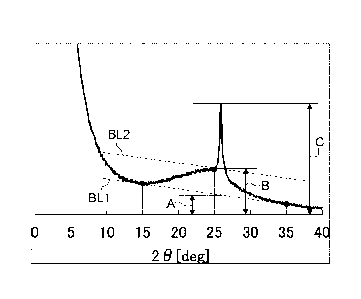
[Figure 11 Figure 1 is an explanatory view (photograph) showing a
crystallized
material (inside a white dotted line) which is confirmed by TEM observation of
a carbon
material for use as a catalyst carrier of Experimental Example 27 of the
present disclosure.
[Figure 2] Figure 2 is a diagram for explaining a method of obtaining A
value, B value,
and C value respectively from a powder X-ray diffraction spectrum in
determining the content
of crystallized material of the present disclosure.
[Figure 3] Figure 3 is powder X-ray diffraction spectra of Experimental
Example 5,
Test Example 7, and Test Example 8 of the present disclosure.
[Figure 4] Figure 4 is powder X-ray diffraction spectra of Experimental
Example 26,
Experimental Example 27, Experimental Example 28, Experimental Example 29, and
Experimental Example 30 of the present disclosure.
[Figure 5A] Figure 5A is an explanatory view (photograph) for showing a
dendritic
structure which is recognized when SEM observation is performed on the carbon
material for
use as a catalyst carrier of Experimental Example 5 of the present disclosure
(The bar at the
lower right in the figure shows 1 p.m).
[Figure 5 B] Figure 5B is an explanatory view (photograph) for showing a
dendritic
structure which is recognized when SEM observation is performed on the carbon
material for
use as a catalyst carrier of Experimental Example 5 of the present disclosure
(The bar at the
lower right in the figure shows 5 p.m).
[Figure 6] Figure 6 is a diagram for explaining a method of measuring a
branch
diameter of a carbon material for use as a catalyst carrier of the present
disclosure.
DESCRIPTION OF EMBODIMENTS
[0023] A carbon material for use as a catalyst carrier of a polymer
electrolyte fuel cell of the
present disclosure, and a method of producing the same will be described below
in detail.
A carbon material for use as a catalyst carrier of a polymer electrolyte fuel
cell of the
present disclosure is a porous carbon material, which satisfies the following
(1), (2), (3) and
(4) at the same time.
(1) The content of a crystallized material defined below is 1.6 or less;
wherein the content of a crystallized material is determined by [(C/A) -
(B/A)], when
the carbon material for use as a catalyst carrier is heated at 2050 C in an
inert atmosphere for
1 hour and powder X-ray diffractometry is performed, and the intensity value
of an
intersection of the baseline of a diffraction peak of the (002) plane and the
perpendicular
11
CA 03058374 2019-09-27
dropped from a second peak appearing near the diffraction angle of 25.5 to
26.5 in the
diffraction peak of the (002) plane is defined as A value, the intensity value
of an intersection
of the baseline of the second peak near the diffraction angle of 25.5 to 26.5
and the
perpendicular dropped from the second peak near the diffraction angle of 25.5
to 26.5 is
defined as B value, and the intensity of the second peak near the diffraction
angle of 25.5 to
26.5 is defined as C value;
(2) the BET specific surface area obtained by a BET analysis of a nitrogen
gas
adsorption isotherm is from 400 to 1500 m2/g;
(3) the cumulative pore volume V2-10 with respect to a pore diameter of
from 2 to 10 nm
obtained by an analysis of a nitrogen gas adsorption isotherm using the
Dollimore-Heal
method is from 0.4 to 1.5 mL/g, and
(4) the nitrogen gas adsorption amount V macro between a relative pressure
of 0.95 and
0.99 in a nitrogen gas adsorption isotherm is from 300 to 1200 cc(STP)/g.
[0024] First of all, the above (1) refers to that in a carbon material for use
as a catalyst
carrier of the present disclosure, formation and inclusion of coarse massive
carbon
(crystallized material) leading to decrease in the yield at a classification
treatment are
suppressed to the extent possible. Then, as a method of indicating the content
of such a
crystallized material, the powder X-ray diffraction method was used after
heating the carbon
material for use as a catalyst carrier in an inert atmosphere at 2050 C for 1
hour.
In this regard, the meaning of heating in an inert atmosphere at 2050 C for 1
hour is,
although already described above, as follows. The carbon with low aromaticity
(soot) is
conceivably easily graphitizable carbon, which is easily crystallized by a
heat treatment, and it
has been known that most of easily graphitizable carbon graphitizes rapidly
from about
2000 C [Tetsuo Iwashita, New-Introduction to Carbon Materials (edit. The
Carbon Society of
Japan (1996) pp. 24-31], and the carbon with low aromaticity (soot)
conceivably exhibits
similar crystallization behavior. Meanwhile, it has been found that the carbon
with high
aromaticity forming the skeleton of a carbon material for use as a catalyst
carrier crystallizes
abruptly near 2100 C. Further, in a case where the temperature of the heat
treatment step
itself, which will be described below, is relatively low, namely as low as
2000 C or less, even
if the carbon having low aromaticity (soot) formed and included therein, a
crystallized
material is hardly formed. Despite such a situation, it has been still found
that the degree of
formation of carbon having low aromaticity (soot) may be actually determined
and verified as
an evaluation of the obtained carbon material for use as a catalyst carrier.
As indicated in Figures 2, 3, and 4 described below, a relatively gentle
diffraction
peak of the (002) plane corresponding to carbon consisting of several layers
of randomly
12
CA 03058374 2019-09-27
stacked graphene sheets appears near the diffraction angle range of from 200
to 30 in the
obtained powder X-ray diffraction spectrum. A sharp peak appearing therein
near the
diffraction angle of from 25.5 to 26.5 (herein occasionally referred to as a
"second peak") is
known as a diffraction peak derived from a graphite structure. In the present
disclosure, this
sharp peak appearing near the diffraction angle of from 25.5 to 26.5 is
deemed as a peak
indicating a crystallized material, and this intensity is defined as as the C
value. However,
since the intensity of the peak of a crystallized material and the intensity
of a component
corresponding to carbon consisting of several layers of randomly stacked
graphene sheets are
superimposed to give the C value, it is necessary to separate them.
Meanwhile, with respect to the A value in the present disclosure, the
intensity value
of an intersection of the perpendicular dropped from the sharp second peak
appearing near the
diffraction angle of 25.5 to 26.50 and the line connecting the relatively
gentle spectrum point
of the (002) plane at the diffraction angle of 15 and the same at the
diffraction angle of 35 is
defined as A value. The line connecting the spectrum point of the (002) plane
at the
diffraction angle of 15 and the same at the diffraction angle of 35
represents the baseline of
the diffraction peak of the (002) plane (denoted as BL1 in Figure 2).
With respect to the B value in the present disclosure, first translating
parallel the line
connecting the spectrum point at the diffraction angle of 15 and the same at
the diffraction
angle of 35 in the Y-axis direction to the intersection of the powder X-ray
diffraction
spectrum with the perpendicular at the diffraction angle of 25 to draw the
baseline (denoted
as BL2 in Figure 2) of the second peak near the diffraction angle of 25.5 to
26.5 , the
intensity value of an intersection of the baseline of the second peak with the
perpendicular
dropped from the second peak is defined as B value. The B value represents the
intensity of
a component corresponding to carbon consisting of several layers of randomly
stacked
graphene sheets.
In this regard, "near the diffraction angle of 25.5 to 26.5 " means that the
diffraction
angle is in a range of "from 25.5 - 0.5 to 26.5 + 0.5 ".
[0025] Then, based on the intensity ratio (C/A) of the C value to the A value,
a value
superimposing the intensity of the peak indicating a crystallized material and
the intensity of a
component corresponding to carbon consisting of several layers of randomly
stacked
graphene sheets eliminating the influence of the baseline is found. Also,
based on the
intensity ratio (B/A) of the B value to the A value, the intensity of the peak
indicating a
crystallized material, and the intensity of a component corresponding to
carbon consisting of
several layers of randomly stacked graphene sheets eliminating the influence
of the baseline
are to be found. Then the content of a crystallized material [(C/A) - (B/A)]
calculated from
13
CA 03058374 2019-09-27
the difference between the two is an indicator of the intensity solely
relevant to the peak
attributable to a crystallized material, and represents that the existing
amount of a crystallized
material is low. Such concept and means were created because the crystallized
material may
be expressed with high reproducibility and also with good correlation with the
content at a
classification as demonstrated in Examples described below.
It is preferable that formation and inclusion of such a crystallized material
in a
carbon material for use as a catalyst carrier according to the present
disclosure is suppressed
to the extent possible in order to keep the yield high at a classification
treatment. Therefore,
it is required that [(C/A) - (B/A)] indicating the content of a crystallized
material should be as
low as possible, namely the content of a crystallized material [(C/A) - (B/A)]
is required to be
1.6 or less, preferably 1.5 or less, more preferably 1.4 or less, and most
preferably the content
of a crystallized material is as close to zero as possible. When the content
of a crystallized
material [(C/A) - (B/A)] becomes so high beyond 1.6, there arises a risk that
the amount of the
crystallized material becomes too high and the yield at a classification
treatment may decrease.
Further, since catalyst particles supported on a crystallized material exhibit
weak interaction
with the surface of the carbon material, there arises another risk that they
may fall off and
aggregate more easily.
In this regard, it has been known that the degree of crystallinity of a carbon
material
generally depends on the heat treatment temperature, and in a case where a
carbon material
for use as a catalyst carrier has been heat-treated in an inert atmosphere at
2050 C or higher,
even when it is heat-treated in an inert atmosphere at 2050 C, this has little
influence on the
degree of crystallinity, and the content of a crystallized material [(C/A) -
(B/A)] does not
change.
Meanwhile, the content of a crystallized material is a value measured by the
measuring method shown in Examples described below.
[0026] For the carbon material for use as a catalyst carrier according to the
present
disclosure, it is necessary that the BET specific surface area determined by a
BET analysis of
a nitrogen gas adsorption isotherm as described in (2) above is from 400 to
1500 m2/g, and
preferably from 500 m2/g to 1,400 m2/g. When the BET specific surface area is
400 m2/g or
more, and preferably 500 m2/g or more, the catalyst metal particles with a
size of several
nanometers are supported in a well dispersed state, namely in a state where
individual
particles can exist keeping a certain interparticle distance among the
catalyst metal particles.
On the contrary, when the BET specific surface area is less than 400 m2/g, the
interparticle
distance among the catalyst metal particles becomes too short, and it may
become difficult to
support the catalyst metal particles at a high density and uniformly. As a
result, the effective
14
CA 03058374 2019-09-27
area of the catalyst metal particles may decrease and the fuel cell
characteristics may greatly
deteriorate. Meanwhile, when the same exceeds 1500 m2/g, since the edge
portion in a
porous carbon material increases, there arises a risk that decrease in
practical crystallinity
occurs and the durability tends to be lowered.
The BET specific surface area is a value measured by the measuring method
shown
in Examples described below.
[0027] Furthermore, for the carbon material for use as a catalyst carrier
according to the
present disclosure as described in (3) above, it is necessary that the
cumulative pore volume
V210 with respect to a pore diameter of from 2 to 10 nm obtained by an
analysis of a nitrogen
gas adsorption isotherm using the Dollimore-Heal method is from 0.4 to 1.5
mL/g, and
preferably from 0.5 to 1.0 mL/g. When the pores have a size of from 2 to 10
nm, catalyst
metal fine particles usually adjusted to have a diameter of several
milometers, are dispersed in
the pores in a highly dispersed state, which contributes favorably to the
catalyst utilization
rate. In a case where the pore volume V2_10 is less than 0.4 mL/g, the volume
with respect to
the pore area is so small, that the average pore size becomes small. When the
platinum fine
particles as the catalyst metal are supported in the pores, the gaps between
the pore wall and
the platinum fine particles become small, so that the gas diffusion is reduced
and there arises a
risk that the high current characteristics may be deteriorated. On the
contrary, in a case
where V2-10 exceeds 1.5 mL/g, the skeleton as a carbon material for use as a
carrier becomes
thin and the oxidation exhaustion resistance decreases. At the same time, the
skeleton of the
carbon material for use as a carrier is easily destroyed by stirring necessary
for preparing a
catalyst layer ink for preparing a catalyst layer, and characteristics derived
from the shape
may not be exhibited.
The cumulative pore volume V2-10 is a value measured by the measurement method
shown in Examples described below.
[0028] Further, with respect to a carbon material for use as a catalyst
carrier of the present
disclosure, from the viewpoint of improving the crystallinity, and the
durability in an
environment using a fuel cell, the half-value width AG of a G-band detected in
a range of
from 1550 to 1650 cm-I of a Raman spectrum is preferably from 50 to 70 crn-I,
and more
preferably from 50 to 65 cm* It is said that the AG represents an expanse of
the carbon
layer plane of a carbon material, and when AG is less than 50 cm-I, the carbon
layer plane
extends excessively so that the area of edge portions of the carbon layer
plane forming pore
walls decreases, and the support property for catalyst metal particles on the
pore walls tends
to deteriorate. On the contrary, if it exceeds 70 cm-I, the carbon layer plane
is narrow so that
CA 03058374 2019-09-27
the area of edge portions of the carbon layer plane liable to oxidative
consumption increases,
and therefore the durability tends to deteriorate.
The half value width AG of the G-band is a value measured by the measurement
method shown in Examples described below.
[0029] Further, with respect to a carbon material for use as a catalyst
carrier of the present
disclosure, from the viewpoint of gas diffusibility inside the micropores
formed in a catalyst
layer, as in the above (4), the nitrogen gas adsorption amount Vmacro adsorbed
between a
relative pressure of 0.95 and 0.99 in a nitrogen gas adsorption isotherm is
required to be from
300 to 1200 cc(STP)/g. The nitrogen gas adsorption amount Vmacro is more
preferably from
300 to 800 cc(STP)/g. The nitrogen gas adsorption amount Vmacro between a
relative
pressure of 0.95 and 0.99 represents the size of macropores formed from the
gaps among
primary particles. When this value falls within the above range, the three-
dimensional
dendritic structure of a carbon material is highly developed. By
developing the
three-dimensional dendritic structure, when used in a fuel cell, a situation
occurring due to
insufficient supply of a raw material gas (H2, or 02), or due to poor
discharge performance of
generated H20 (situation where a cell reaction is hindered) may be avoided.
Namely, a fuel
cell with excellent high current characteristics can be formed. On the
contrary, when the
Vmacro exceeds 1200, the voids in a carbon material increase, so that the
thickness of a catalyst
layer increases when it is applied to a catalyst carrier for a fuel cell, and
the diffusion distance
of a raw material gas (H2, or 02) increases to deteriorate the power
generation characteristics.
The nitrogen gas adsorption amount Vmacro is a value measured by the
measurement
method shown in Examples described below.
[0030] In a method of producing such a carbon material for use as a catalyst
carrier
according to the present disclosure, carbon with low aromaticity (soot) to be
included in a
carbon material intermediate obtained by self-decomposing explosion of silver
acetylide is
required to be eliminated to the extent possible. As a result of the detailed
investigations by
the present inventors, the following findings were obtained. In order to
eliminate the carbon
having low aromaticity (soot) to the extent possible, if the generation of the
aforedescribed
carbon having low aromaticity (soot) itself is suppressed, it is possible to
suppress formation
of a crystallized material even after subsequent steps. From this point of
view, as described
above, the amount of an acetylene gas blown in at the silver acetylide
producing step should
be precisely controlled to the molar equivalent (acetylene/silver nitrate =
0.5) or lower. By
doing so, formation and inclusion of a crystallized material at a later stage
can be suppressed,
namely the content of a crystallized material defined as above in connection
with a powder
X-ray diffraction spectrum obtained by powder X-ray diffractometry after
heating the carbon
16
CA 03058374 2019-09-27
material for use as a catalyst carrier in an inert atmosphere at 2050 C for 1
hour, may be
decreased. As a result, the yield at a classification treatment can be
increased.
The amount-of-substance ratio of the acetylene gas to the silver nitrate
(acetylene/silver nitrate) is preferably 0.500 or less, and more preferably
0.498 or less.
When the amount-of-substance ratio (acetylene/silver nitrate) is larger than
0.500, the amount
of acetylene adsorbed on the formed silver acetylide becomes excessive, and
carbon with low
aromaticity (soot) derived from the adsorbed acetylene to be formed after the
decomposition
step is presumably increased. As a result, there is a risk that a large amount
of a crystallized
material is generated after the heat treatment step describe below, namely
that the yield at the
classification treatment may be lowered.
The lower limit of the amount-of-substance ratio (acetylene/silver nitrate) is
preferably 0.370 or more because the presence of unreacted silver leads to
increase in
production cost, more preferably 0.400 or more, and further preferably 0.450
or more.
When the amount-of-substance ratio (acetylene/silver nitrate) is less than
0.37, the
crystal size of the formed silver acetylide becomes small, and the specific
surface area and the
mesopore volume of porous carbon obtained by removing silver from a composite
material
made of silver obtained by decomposition and carbon become lower, and also the
yield at a
classification treatment becomes lower. This is presumably because the crystal
size of silver
acetylide decreases as the blow-in amount of an acetylene gas decreases, and
therefore the
total amount of energy which is generated in decomposition and propagates
through the silver
acetylide crystal decreases, so that the graphene layer does not develop
sufficiently and the
amount of carbon with low aromaticity (soot) increases.
Meanwhile, although there is no particular restriction on a method of
adjusting the
amount of an acetylene gas to be blown in at the acetylide producing step,
namely a method
of adjusting the molar ratio (acetylene/silver nitrate), the flow rate of the
blown-in acetylene
gas, or the blow time thereof should preferably be adjusted.
[0031] It is conjectured that formation of carbon with low aromaticity may be
excluded to
the extent possible by adjusting the amount of an acetylene gas in the silver
acetylide
producing step as described above. By doing so, formation and inclusion of a
crystallized
material is excluded to the extent possible, but in other aspects it is
possible to prepare a
carbon material for use as a catalyst carrier of the present disclosure by the
same method as
the conventional method.
In other words, a carbon material for use as a catalyst carrier of the present
disclosure
may be produced by blowing a predetermine amount of acetylene gas into a
reaction solution
composed of an aqueous ammonia solution of silver nitrate to synthesize silver
acetylide
17
CA 03058374 2019-09-27
(silver acetylide producing step), causing a self-decomposing and explosive
reaction of the
obtained silver acetylide at a temperature of from 120 to 400 C to recover a
carbon material
intermediate (decomposition step), bringing the recovered carbon material
intermediate into
contact with a nitric acid solution to clean the carbon material intermediate
by removing silver
particles (washing treatment step), and heat-treating the cleaned carbon
material intermediate
in a vacuum, or an inert gas atmosphere at a temperature of from 1400 to 2100
C, and
preferably 1800 C to 2100 C (heat treatment step). Each step will be described
in detail
below.
[0032] (Silver Acetylide Producing Step)
In the present disclosure, the silver acetylide producing step is carried out
by
adjusting the amount-of-substance ratio of acetylene gas to the silver nitrate
as described
above. Examples of the contacting method of the acetylene gas include a method
in which
an acetylene gas flows through a silver nitrate aqueous solution, or more
specifically, a
method in which the acetylene gas is blown into a silver nitrate aqueous
solution. During
contact between the silver nitrate aqueous solution and the acetylene gas, the
silver nitrate
aqueous solution may be irradiated with ultrasonic waves. This means has an
effect to
promote dissolution or dispersion of the acetylene gas into the silver nitrate
aqueous solution.
During such contact between the silver nitrate aqueous solution and the
acetylene gas, it is
preferable to stir the silver nitrate aqueous solution. Since the contact
frequency between the
acetylene gas and the silver nitrate aqueous solution is increased by this
means, silver
acetylide is formed efficiently. The stirring may be conducted using a general
stirring blade,
or using a stirring bar for a magnetic stirrer. As a result, silver acetylide
can be obtained as a
bulky precipitate of white crystals.
[0033] (Decomposition Step)
Next, the obtained silver acetylide is decomposed by heating to obtain a
carbon
material intermediate. By heating silver acetylide, silver acetylide explodes
on the nanoseale,
and phase separation to silver and carbon occurs, during which silver forms
nanosized
particles, or is gasified by a reaction heat to erupt to the surface. Since
three acetylenic
compounds such as acetylene molecules are apt to form together a benzene ring,
the carbon
has a structure with high aromaticity. Further, silver forms nanoparticles,
and therefore a
carbon phase having eliminated silver becomes a porous structure.
[0034] Heating of silver acetylide may be carried out, for example, as
follows. The
obtained precipitate of silver acetylide is heated in a reduced pressure
atmosphere, for
example, between 40 C and 100 C (hereinafter referred to as ''first heat
treatment"). By this
heating, the solvent of the reaction solution remaining in the silver
acetylide can be removed,
18
CA 03058374 2019-09-27
so that waste of thermal energy of explosion as the sensible heat of the phase
transition of the
solvent to the gas phase may be prevented, and the decomposition of silver
acetylide can be
performed efficiently. In this regard, at the aforementioned temperature
silver acetylide does
not decompose.
[0035] Next, the silver acetylide from which the solvent has been removed is
heated, for
example, between 140 C and 400 C (hereinafter referred to as "second heat
treatment"). By
heating silver acetylide to such a relatively high temperature, silver
acetylide explodes on the
nanoscale and decomposes, and silver and carbon form nanostructures,
respectively. Thus, a
carbon material intermediate containing silver and carbon is obtained.
The basic structure of a carbon phase portion of the composite material is
mainly
composed of several layers of graphene through polycyclic aromatic formation
from
acetylenic compounds as described above. Further, since in the above composite
material,
silver forms nanoscale particles in the explosion process, a carbon material
from which silver
particles are removed can form a carbon material having a large specific
surface area and high
porosity.
[0036] (Washing Treatment Step)
For removing silver from a carbon material intermediate, a publicly known
method
may be used. For example, a cleaned carbon material intermediate, in which
silver
remaining on the surface or inside of the carbon material intermediate is
removed by, for
example, immersing the carbon material intermediate containing silver and
carbon in hot
nitric acid to dissolve silver, may be obtained
[0037] (Heat Treatment Step)
The cleaned carbon material intermediate is heat-treated in a vacuum, or an
inert gas
atmosphere at a temperature of from 1400 to 2100 C and preferably from 1800 to
2100 C
(hereinafter also referred to as "third heat treatment") to yield a carbon
material for use as a
catalyst carrier. The crystal of the carbon material for use as a catalyst
carrier may be grown
by the heat treatment performed in this step, and the crystallinity of the
carbon material for
use as a catalyst carrier may be adjusted or regulated by the calcination
temperature. When
the carbon material for use as a catalyst carrier is used, for example, as a
catalyst carrier for an
electrode of a polymer electrolyte fuel cell, the porous carbon material is
exposed to an
environment, where the temperature is relatively high, for example, about 80
C, the acidity is
strongly acidic with a pH of 1 or less, and the potential is as high as 1.3 V
vs SHE. In such
an environment, carbon in the porous carbon material tends to be oxidatively
consumed.
Therefore, when the porous carbon material is used as a catalyst carrier, it
is important that the
crystallinity should be enhanced in this step.
19
CO. 03058374 2019-09-27
[0038] As described above, when the temperature of the heat treatment step
exceeds 2100 C,
even in the carbon with high aromaticity, which will eventually form the
skeleton of a carbon
material for use as a catalyst carrier, crystallization suddenly advances.
Therefore, in the
subsequent classification step, crushing or pulverization becomes hardly
performable, and the
yield at a classification treatment may decrease. Therefore, the temperature
of the heat
treatment step is preferably 2100 C or less. The lower limit of the
temperature at the heat
treatment step needs to be 1400 C or higher, and preferably 1800 C or higher
from the
viewpoint of improving the durability (AG as mentioned above) of a carbon
material for use
as a catalyst carrier to be yielded.
The heat treatment step may be, for example but without limitation thereto,
performed in a reduced pressure atmosphere, or in an inert gas atmosphere, and
preferably in
an inert gas atmosphere. There is no particular restriction on an inert gas,
and, for example,
nitrogen, or argon may be used.
[0039] A carbon material for use as a catalyst carrier of the present
disclosure is as a catalyst
carrier preferably composed of dendritic carbon nanostructures having a three-
dimensional
dendritic structure in which a rod-shaped body or a ring-shaped body is
branched
three-dimensionally. This dendritic carbon nanostructure is not only
equivalent or superior
to the conventional similar dendritic carbon nanostructure in the BET specific
surface area
and durability, but also freed from a coarse crystallized material to the
extent possible as
described above. Therefore, the dendritic carbon nanostructure can further
increase the yield
at the classification treatment, and further, in a catalyst layer prepared
using the carbon
material as a catalyst carrier, mesopores suitable for diffusing a reactive
gas without resistance,
and discharging the water produced in the catalyst layer (produced water)
without delay, may
be formed, and moreover a polymer electrolyte fuel cell, with which there is
little risk that the
utilization ratio of a catalyst metal decreases, and which is superior in the
durability as a fuel
cell, may be obtained.
[0040] In this regard, a dendritic carbon nanostructure represents a dendritic
structure with
branching having, for example, a branch diameter of from 10 nm to several 100s
of
nanometers (for example, 500 nm or less (preferably 200 nm or less)).
The branch diameter is measured as follows. Using a scanning electron
microscope
(SEM; SU-9000 manufactured by Hitachi High-Technologies Corporation), SEM
images at 5
visual fields (size 2.5 pnl X 2 um) were observed at 100000-fold
magnification, and branch
diameters were measured at 20 positions in each visual field, and the mean
value of total 100
measurements is regarded as the branch diameter. The branch diameter to be
measured is
the branch diameter at the center between the adjacent two branch points (the
middle part of
CA 03058374 2019-09-27
the branched branch) of a branch of interest (refer to Figure 5A, D in Figure
5A stands for a
branch diameter).
Referring to Figure 6, the method of measuring a branch diameter will be
described.
In Figure 6, one branch of interest is shown. For this branch of interest, the
branch point BP
1 and the branch point BP 2 are specified. Next the specified branch point BP
1 and branch
point BP 2 are connected with a line segment, and the thickness (width) of the
branch is
measured on the perpendicular bisector BC of the line segment connecting the
branch point
BP 1 and the branch point BP 2. The measured thickness (width) of the branch
is a branch
diameter D at one position,
Examples
[0041] A carbon material for use as a catalyst carrier of the present
disclosure and the
production method therefor will be specifically described based on
Experimental Examples.
A powder X-ray diffraction measurement [content of crystallized material], and
the
measurements of the BET specific surface area (m2/g), the cumulative pore
volume V2.10 with
respect to a pore diameter of from 2 to 10 nm, the nitrogen gas adsorption
amount Vmacro
[cc(STP)/g], the half value width AG (cm) of the G band detected in a range of
from 1550 to
1650 cm"' of the Raman spectrum, and the yield (%) at the classification
treatment of carbon
materials for use as a catalyst carrier prepared in the following Experimental
Examples were
respectively conducted as follows. Further, part of the obtained carbon
materials for use as a
catalyst carrier were observed using a transmission electron microscope (TEM)
and a
scanning electron microscope (SEM).
[0042] <Measurement of Powder X-ray Diffraction Spectrum (Content of
Crystallized
Material)>
From the sample prepared in each of the following Experimental Examples, which
was heat-treated in an argon atmosphere at 2050 C for 1 hour, approximately 3
mg was
weighed out. Then this sample was packed compactly on a glass sample plate
(outer size 35
x 50 mm, thickness 2 mm, sample section 20 x 20, sample section depth 0.5 mm;
produced
by Rigaku Corporation) and leveled off such that the upper surface of the
sample becomes
flush with the upper surface of the glass. The sample was mounted on an X-ray
diffractometer (RINT-TTRIII, manufactured by Rigaku Corporation), and the
powder X-ray
diffraction spectrum was measured using Cu-Ka as a radiation source at normal
temperature,
a scanning step of 0.02 , and an angle sweeping rate of 1 /min. The obtained
spectra are as
shown in Figures 2 to 4. Although the diffraction peak position of the (002)
plane of a
graphite crystal is ordinarily at a diffraction angle (20) of about 26.5 , in
the present
disclosure, the diffraction peak of the (002) plane of graphite or high-
crystalline carbon
21
CA 03058374 2019-09-27
similar thereto appeared between 200 and 30 , and a sharp peak corresponding
to a
crystallized material was observed near the diffraction angle of from 25.5 to
26.5 . From the
obtained powder X-ray diffraction spectrum, the intensities corresponding to
the A value, the
B value and the C value were respectively determined according to Figure 2 to
calculate a
content of a crystallized material [(C/A) - (B/A)].
The intensities of A, B and C in the calculation of a content of crystallized
material
are based on the zero point of the spectrum. For example, when only the glass
sample plate
is measured, the diffraction intensity of the glass sample plate compared to
the diffraction
intensity of carbon is sufficiently small, and the influence of the sample
plate on the spectrum
may be ignored. On the other hand, when a background noise is included
significantly as in
the case where a sample plate gives diffraction intensity similar to that of
the carbon spectrum,
it is necessary that a spectrum obtained by measuring porous carbon, from
which the
influence of a background noise is eliminated appropriately, for example by
subtracting the
spectrum obtained in measuring the sample plate alone, should be used for
calculating a
content of crystallized material.
[0043] <Measurement of BET Specific Surface Area (m2/g), Cumulative Pore
Volume V2-10
with respect to a Pore diameter of from 2 to 10 nm, and Nitrogen Gas
Adsorption amount
Vmacro [cc(S TP)/g]>
About 30 mg of the carbon material for use as a catalyst carrier prepared in
each
Experimental Example described below was weighed as a sample, and was dried in
a vacuum
at 200 C for 2 hours. Thereafter, a nitrogen gas adsorption isotherm was
measured using an
automatic specific surface area measuring apparatus (AUTOSORB iQ-MP
manufactured by
Quantachrome Instruments Japan G.K.) and a nitrogen gas as an adsorbate. A BET
analysis
was carried out at the relative pressure of the isotherm during adsorption was
in the range of
from 0.05 to 0.15, then a BET specific surface area was calculated.
Regarding the cumulative pore volume V2-10 with respect to a pore diameter of
from
2 to 10 nm, the similar nitrogen gas adsorption isotherm as above was used and
it was
analyzed and calculated by the Dollimore-Heal method (DH method) using the
attached
software.
Further, regarding the nitrogen gas adsorption amount Vmacro, the difference
between
the adsorption amount [cc(STP)/g] at the relative pressure of 0.95 of the
nitrogen gas
adsorption isotherm similar to the above, and the adsorption amount
[cc(STP)/g] at the
relative pressure of 0.99 was calculated, and regarded as the value of Vmacro
[cc(STP)/g].
[0044] <Half-value width AG (cm-1) of G-band Detected in Range of from 1550 to
1650
cm-1 of Raman Spectrum>
22
CA 03058374 2019-09-27
About 3 mg of the carbon material for use as a catalyst carrier prepared in
each
Experimental Example described below was weighed as a sample. Then the sample
was
mounted on a laser Raman spectrophotometer (model NRS-3100 manufactured by
JASCO
Corporation) to measure a Raman spectrum under measurement conditions:
excitation laser:
532 nm, laser power: 10 mW (sample irradiation power: 1.1 mW), microscope
arrangement:
backscattering, slit: 100 [tm x 100 rim, objective lens: x 100, spot diameter:
1 p.m, exposure
time: 30 sec, observation wavenumber: from 2000 to 300 cm4, and cumulative
number: 6.
From the obtained six spectra, the half value widths AG (cm-') of the so-
called G-bands of
graphite appearing respectively in the vicinity of 1580 cm-1 were determined,
and the mean
value thereof was regarded as a measured value. Rating was made according to
the
following criteria.
[0045] <TEM Observation>
In order to observe the appearance of a crystallized material, observation was
carried
out using a transmission electron microscope on the carbon material for use as
a catalyst
carrier prepared in Experimental Example 27 described below as a sample. The
results are
shown in Figure 1.
[0046] <SEM Observation>
In order to observe the appearance of a dendritic structure, observation was
carried
out using a high resolution scanning electron microscope on the carbon
material for use as a
catalyst carrier prepared in Experimental Example 5 described below as a
sample. The
results are shown in Figure 5A and Figure 5B.
[0047] <Measurement of Yield at Classification Step>
For measuring the yield, as a pulverizing and classifying device, a jet mill
SJ-100GMP manufactured by Nisshin Engineering Inc. was used. Each 100 g of the
carbon
materials for use as a catalyst carrier of Experimental Examples described
below was
subjected to the device for simultaneous pulverization and classification
under the conditions:
pulverization pressure of 0.8 MPa, and powder feed rate of 100 g/hr. The
powder recovered
on the collection filter cloth (filter powder), and the powder classified and
not recovered on
the collection filter cloth due to coarse size (cyclone powder) were collected
and the
respective weights were measured. Then, the yield (%) at the classification
was calculated
by the calculation formula of [(weight of filter powder)/(total weight of
filter powder and
cyclone powder)] x 100. Rating was made according to the following criteria.
[Acceptable Rank]
Good: Yield is not less than 95%.
Fair: Yield is not less than 90% but less than 95%.
23
CA 03058374 2019-09-27
[Rejected Rank]
Poor: Yield is less than 90%.
[0048] [Experimental Example 1]
(1) Silver Acetylide Producing Step
By adding 200 g of a 25% by mass aqueous ammonia solution to 46 g of silver
nitrate, the latter was dissolved. Then 2 L of water was further added
thereto, and residual
oxygen was removed by blowing dry nitrogen therein. Next, an acetylene gas was
blown
into the solution at a flow rate of 100 mL/min for 15 min with stirring and
also applying
vibration by immersing an ultrasonic vibrator to precipitate a solid of silver
acetylide in the
solution. Next, the yielded precipitate was filtered with a membrane filter,
and in doing so
the precipitate was rinsed with methanol, followed by addition of some
methanol so that the
precipitate was impregnated with methanol.
[0049]
(2) Decomposition Process
Approximately 0.5 g of silver acetylide of each Experimental Example yielded
in the
above silver acetylide producing step in a state impregnated with methanol was
placed in a
stainless steel cylindrical container with a diameter of 5 cm. This was then
placed in a
vacuum dryer and dried in a vacuum at from 30 to 40 C for 1 hour to prepare a
silver
particle-encapsulated intermediate derived from silver acetylide (first heat
treatment).
Next, the silver particle-encapsulated intermediate obtained in the first heat
treatment
step at from 30 to 40 C immediately after the vacuum drying was rapidly heated
up to from
160 to 200 C as it was without taking out it from the vacuum electric heating
furnace, and the
heating was continued for 20 mm (second heat treatment). In this course, a
nano-scale
explosive reaction occurred in the container, and the encapsulated silver was
ejected, and a
silver-encapsulated nanostructure (carbon material intermediate) having a
large number of
craters formed on the surface as well as the inside was obtained as a
composite material
containing silver and carbon.
[0050]
(3) Washing Treatment Step
Out of a carbon material intermediate composed of the composite material
containing
silver and carbon obtained in the second heat treatment, 10 g was dipped in
200 mL of a nitric
acid solution having a concentration of 30% by mass to be washed at 90 C for 2
hours to
remove remaining silver particles. Next, nitric acid was removed from the
carbon material
intermediate after washing as above using a centrifuge, and in order to
sufficiently remove
residual nitric acid, the carbon material intermediate after the
centrifugation was again
24
CA 03058374 2019-09-27
dispersed in pure water which was centrifuged again to separate the carbon
material
intermediate (solid) from the liquid. By conducting such a water washing
operation twice, a
carbon material intermediate which was cleaned by removing nitric acid was
obtained.
The cleaned carbon material intermediate was treated in an air atmosphere at
140 C
for 2 hours to remove moisture for drying, and then heat-treated in an argon
stream at 1100 C
for 2 hours to yield a porous carbon material.
[0051]
(4) Heat Treatment Step (Third Heat Treatment)
The temperature of the porous carbon material yielded in the above (3) was
further
raised at 15 C/min up to 2050 C in an argon stream. After reaching a
predetermined
temperature, the temperature was maintained for 2 hours for a heat treatment
to obtain a
carbon material for use as a catalyst carrier according to Experimental
Example 1.
[0052] With respect to the carbon material for use as a catalyst carrier
prepared as above in
Experimental Example 1, a powder X-ray diffraction measurement (content of
crystallized
material), and measurements of the BET specific surface area (m2/g), the
cumulative pore
volume V2-10 of pores having a pore size of from 2 to 10 nm, the nitrogen gas
adsorption
amount Vmacro [cc(STP)/g], the half-value width AG (cm-1) of the G-band
detected in a range
of from 1550 to 1650 cm-I in a Raman spectrum, and the yield at a
classification treatment
(%) were carried out.
The results are shown in Table 1.
[0053] [Experimental Examples 2 to 8]
Respective carbon materials for use as a catalyst carrier were prepared in the
same
manner as in Experimental Example 1 and evaluated in the same manner, except
that the
acetylene gas blowing time in the silver acetylide producing step was changed
to 20 min, 22
min, 23 min, 25 min, 27 min, 28 min, or 30 min, respectively. The results are
shown in
Table I.
[0054] [Experimental Examples 9 to 11]
Respective carbon materials for use as a catalyst carrier were prepared in the
same
manner as in Experimental Example 1 and evaluated in the same manner, except
that the
temperature of the heat treatment step was changed to 2025 C, and the
acetylene gas blowing
time in the silver acetylide producing step was changed to 25 min, 28 min, or
30 min
respectively. The results are shown in Table 1.
[0055] [Experimental Examples 12 to 17]
Respective carbon materials for use as a catalyst carrier were prepared in the
same
manner as in Experimental Example 1 and evaluated in the same manner, except
that the
CA 03058374 2019-09-27
temperature of the heat treatment step was changed to 2000 C, and the
acetylene gas blowing
time in the silver acetylide producing step was changed to 15 min, 20 min, 23
min, 25 min, 28
mm, or 30 mm respectively. The results are shown in Table 1.
[0056] [Experimental Examples 18 to 20]
Respective carbon materials for use as a catalyst carrier were prepared in the
same
manner as in Experimental Example 1 and evaluated in the same manner, except
that the
temperature of the heat treatment step was changed to 1900 C, and the
acetylene gas blowing
time in the silver acetylide producing step was changed to 25 mm, 28 mm, or 30
min
respectively. The results are shown in Table 1.
[0057] [Experimental Examples 21 and 22]
Respective carbon materials for use as a catalyst carrier were prepared in the
same
manner as in Experimental Example 1 and evaluated in the same manner, except
that the
temperature of the heat treatment step was changed to 1800 C, and the
acetylene gas blowing
time in the silver acetylide producing step was changed to 28 min, or 30 min
respectively.
The results are shown in Table 1.
[0058] [Experimental Examples 23 and 24]
Respective carbon materials for use as a catalyst carrier were prepared in the
same
manner as in Experimental Example 1 and evaluated in the same manner, except
that the
temperature of the heat treatment step was changed to 1700 C, and the
acetylene gas blowing
time in the silver acetylide producing step was changed to 28 mm, or 30 min
respectively.
The results are shown in Table 1.
[0059] [Experimental Example 25]
Respective carbon materials for use as a catalyst carrier were prepared in the
same
manner as in Experimental Example 1 and evaluated in the same manner, except
that the
temperature of the heat treatment step was changed to 1500 C, and the
acetylene gas blowing
time in the silver acetylide producing step was changed to 30 min. The results
are shown in
Table 1.
[0060] [Experimental Examples 26 and 27]
Respective carbon materials for use as a catalyst carrier were prepared in the
same
manner as in Experimental Example 1 and evaluated in the same manner, except
that the
acetylene gas blowing time in the silver acetylide producing step was changed
to 32 min, or
35 mm respectively. The results are shown in Table 2.
[0061] [Experimental Examples 28 and 29]
Respective carbon materials for use as a catalyst carrier were prepared in the
same
manner as in Experimental Example 1 and evaluated in the same manner, except
that the
26
CA 03058374 2019-09-27
temperature of the heat treatment step was changed to 2025 C, and the
acetylene gas blowing
time in the silver acetylide producing step was changed to 32 mm, or 35 mm.
The results are
shown in Table 2.
[0062] [Experimental Examples 30 to 34]
Respective carbon materials for use as a catalyst carrier were prepared in the
same
manner as in Experimental Example 1 and evaluated in the same manner, except
that the
temperature of the heat treatment step was changed to 2200 C, and the
acetylene gas blowing
time in the silver acetylide producing step was changed to 25 mm, 28 min, 30
min, 32 mm, or
35 min respectively. The results are shown in Table 2.
[0063] [Experimental Examples 35 and 36]
Respective carbon materials for use as a catalyst carrier were prepared in the
same
manner as in Experimental Example 1 and evaluated in the same manner, except
that the
temperature of the heat treatment step was changed to 2000 C, and the
acetylene gas blowing
time in the silver acetylide producing step was changed to 32 min, or 35 min
respectively.
The results are shown in Table 2.
[0064] [Experimental Examples 37 and 38]
Respective carbon materials for use as a catalyst carrier were prepared in the
same
manner as in Experimental Example 1 and evaluated in the same manner, except
that the
temperature of the heat treatment step was changed to 1900 C, and the
acetylene gas blowing
time in the silver acetylide producing step was changed to 32 min, or 35 min
respectively.
The results are shown in Table 2.
[0065] [Experimental Examples 39 and 40]
Respective carbon materials for use as a catalyst carrier were prepared in the
same
manner as in Experimental Example 1 and evaluated in the same manner, except
that the
temperature of the heat treatment step was changed to 1800 C, and the
acetylene gas blowing
time in the silver acetylide producing step was changed to 32 mm, or 35 min
respectively.
The results are shown in Table 2.
[0066] [Experimental Example 41]
Respective carbon materials for use as a catalyst carrier were prepared in the
same
manner as in Experimental Example 1 and evaluated in the same manner, except
that the
temperature of the heat treatment step was changed to 1700 C, and the
acetylene gas blowing
time in the silver acetylide producing step was changed to 32 min. The results
are shown in
Table 2.
27
CA 03058374 2019-09-27
[0067] [Experimental Examples 42 and 43]
Respective carbon materials for use as a catalyst carrier were prepared in the
same
manner as in Experimental Example 1 and evaluated in the same manner, except
that the
temperature of the heat treatment step was changed to 1500 C, and the
acetylene gas blowing
time in the silver acetylide producing step was changed to 32 min, or 35 min
respectively.
The results are shown in Table 2.
[0068] [Experimental Example 44]
Respective carbon materials for use as a catalyst carrier were prepared in the
same
manner as in Experimental Example 1 and evaluated in the same manner, except
that the
temperature of the heat treatment step was changed to 2300 C, and the
acetylene gas blowing
time in the silver acetylide producing step was changed to 25 min. The results
are shown in
Table 2.
[0069] [Experimental Examples 45 and 46]
Respective carbon materials for use as a catalyst carrier were prepared in the
same
manner as in Experimental Example 1 and evaluated in the same manner, except
that the
temperature of the heat treatment step was changed to 2300 C, and the
acetylene gas blowing
time in the silver acetylide producing step was changed to 30 min, or 35 min
respectively.
The results are shown in Table 2.
[0070] [Experimental Example 47]
Respective carbon materials for use as a catalyst carrier were prepared in the
same
manner as in Experimental Example 1 and evaluated in the same manner, except
that the
temperature of the heat treatment step was changed to 1300 C, and the
acetylene gas blowing
time in the silver acetylide producing step was changed to 30 mm. The results
are shown in
Table 2.
[0071] [Experimental Example 48]
Respective carbon materials for use as a catalyst carrier were prepared in the
same
manner as in Experimental Example 1 and evaluated in the same manner, except
that the
temperature of the heat treatment step was changed to 1100 C, and the
acetylene gas blowing
time in the silver acetylide producing step was changed to 30 min. The results
are shown in
Table 2.
[0072] [Experimental Examples 49 to 51]
In addition, a commercially available porous carbon material was examined in
Experimental Examples 49 to 51.
As a commercially available porous carbon material, KETJENBLACK EC600JD
produced by Lion Specialty Chemicals Co., Ltd., which is a porous carbon
having a dendritic
28
CA 03058374 2019-09-27
structure with well-developed pores, and a large specific surface area, was
heated in an argon
stream up to 1400 C at a temperature elevation rate of 15 C/min. After
reaching a
predetermined temperature, the temperature was maintained for 2 hours for a
heat treatment to
obtain a carbon material for use as a catalyst carrier according to
Experimental Example 49.
[0073] Carbon materials for use as a catalyst carrier according to
Experimental Examples 50
and 51 were prepared in the same manner as in Experimental Example 49, except
that the
temperature of the heat treatment step was changed to 1800 C or 2000 C.
[0074] With respect to the carbon materials for use as a catalyst carrier of
Experimental
Examples 49 to 51 prepared as described above, measurements of the BET
specific surface
area (m2/g), the cumulative pore volume V2-10 of pores having a pore size of
from 2 to 10 rim,
the nitrogen gas adsorption amount Vmacro [cc(STP)/g], the half-value width AG
(cm') of the
G-band detected in a range of from 1550 to 1650 cm-1 in a Raman spectrum were
carried out
by the methods described above.
Meanwhile, with respect to the carbon materials for use as a catalyst carrier
of
Experimental Examples 49 to 51 (calcined products of Ketjenblack), a peak was
not detected
near the diffraction angle of from 25.5 to 26.5 in the powder X-ray
diffraction spectrum.
[0075] <Preparation of Catalyst, Production of Catalyst Layer, Preparation of
MEA,
Assembly of Fuel Cell, and Evaluation of Battery Performance (Durability)>
Next, using each of the thus prepared carbon materials for use as a catalyst
carrier
after the classification treatment (provided that the carbon materials for use
as a catalyst
carrier of Examples 49 to 51 were not subjected to a classification treatment,
but ground in an
agate mortar for 5 min), catalysts for a polymer electrolyte fuel cell, on
which a catalyst metal
was supported, were prepared as described below. Further, using an obtained
catalyst, an ink
solution for a catalyst layer was prepared. Next, using the ink solution for a
catalyst layer, a
catalyst layer was formed, and using the formed catalyst layer a membrane
electrode
assembly (MEA) was produced. The produced MEA was fitted into a fuel cell, and
a power
generation test was performed using a fuel cell measuring device. Preparation
of each
component and cell evaluation by a power generation test will be described in
detail below.
[0076]
(1)
Preparation of Catalyst for Polymer Electrolyte Fuel Cell (Carbon Material
Supporting Platinum)
Each carbon material for use as a catalyst carrier prepared as above was
dispersed in
distilled water, and formaldehyde was added to the dispersion. The dispersion
was placed in
a water bath set at 40 C, and when the temperature of the dispersion reached
the water bath
temperature of 40 C, an aqueous nitric acid solution of a dinitrodiamine Pt
complex was
29
CA 03058374 2019-09-27
slowly poured into the dispersion with stirring. Then, stirring was continued
for about 2
hours, the dispersion was filtrated, and the obtained solid was washed. The
solid obtained in
this way was dried in a vacuum at 90 C, then pulverized in a mortar, and then
heat-treated at
200 C in an argon atmosphere containing 5% by volume of hydrogen for 1 hour to
yield a
carbon material supporting platinum catalyst particles. The supported platinum
amount of
the carbon material supporting platinum was regulated to 25% by mass with
respect to the
total mass of the carbon material for use as a catalyst carrier and the
platinum particles, which
was confirmed by a measurement based on inductively coupled plasma atomic
emission
spectrometry (ICP-AES).
[0077]
(2) Preparation of Catalyst Layer
A catalyst layer ink liquid containing a mixture of a Pt catalyst and an
electrolyte
resin was prepared using the carbon material supporting platinum (Pt catalyst)
prepared as
described above, and Nation (produced by DuPont Co., Ltd., persulfonic acid-
based ion
exchange resin) as an electrolyte resin; mixing the Pt catalyst and the Nafion
in a argon
atmosphere, such that the mass of the Nafion solid component is 1.0 times as
much as the
mass of the carbon material supporting platinum catalyst particles, and 0.5
times as much as
non-porous carbon; stirring gently; then crushing the Pt catalyst by
ultrasonic waves; and
further adjusting the mixture to 1.0% by mass in terms of total solid
concentration of the Pt
catalyst and the electrolyte resin by adding ethanol.
[0078] To each catalyst layer ink solution having a solid concentration of
1.0% by mass thus
prepared, ethanol was further added to prepare a catalyst layer ink solution
for spray coating
having a platinum concentration of 0.5% by mass. The catalyst layer ink
solution for spray
coating was sprayed on a Teflon sheet after adjustment of spraying conditions
such that the
mass of platinum per unit area of catalyst layer (hereinafter referred to as
"platinum basis
weight") become 0.1 mg/cm', and a drying treatment was carried out in argon at
120 C for 60
min to complete a catalyst layer.
[0079]
(3) Preparation of MEA
An MEA (membrane electrode assembly) was produced using the catalyst layer
prepared as above by the following method.
A square electrolyte membrane of 6 cm on a side of was cut out from a Nafion
membrane (NR 211 produced by DuPont Co., Ltd.).
Each of the anode or cathode catalyst layer coated on a Teflon sheet was cut
out
with a cutter knife into a square of 2.5 cm on a side.
CA 03058374 2019-09-27
Between the anode catalyst layer and the cathode catalyst layer cut out as
above, the
electrolyte membrane was inserted such that the two catalyst layers sandwich
the central part
of the electrolyte membrane without misalignment from each other. Then the
laminate was
pressed at 120 C under a pressure of 100 kg/cm2 for 10 min, cooled down to
room
temperature, and only the Teflon sheets were peeled off carefully from the
anode and the
cathode to complete an assembly of the catalyst layers and the electrolyte
membrane, in which
the respective catalyst layers of anode and cathode are fixed to the
electrolyte membrane.
[0080] Next, as a gas diffusion layer, a pair of square carbon paper sheets of
2.5 cm on a side
were cut out from carbon paper (35 BC produced by SGL Carbon Co., Ltd.), and
between the
carbon paper sheets, the assembly of the catalyst layers and the electrolyte
membrane was
inserted such that the two catalyst layers of the anode and the cathode are
placed without
misalignment. Then the laminate was pressed at 120 C under a pressure of 50
kg/em2 for 10
min, to compete an MEA.
The basis weights of the catalyst metal component, the carbon material, and
the
electrolyte material in each of the produced MEA were calculated based on the
mass of a
catalyst layer fixed to the Nafion membrane (electrolyte membrane) found from
the mass
difference between the mass of the Teflon sheet before pressing and the mass
of the peeled
Teflon sheet after pressing, and the mass ratio of the components in the
catalyst layer.
[0081]
(4) Evaluation of Power Generation Performance of Fuel Cell
An MEA prepared using each carbon material for use as a catalyst carrier of
each
Experimental Example was fitted into a cell, which was then set on a fuel cell
measuring
apparatus, and the performance of the fuel cell was evaluated by the following
procedure.
On the cathode side air was supplied as an oxidative gas, and on the anode
side pure
hydrogen was supplied as a reactive gas at a back pressure of 0.05 MPa by
regulating the
pressure with a back pressure regulating valve placed downstream of the cell
so that the
respective utilization rates became 40% and 70%. Meanwhile, the cell
temperature was set
at 80 C, and the supplied oxidative gas, and reactive gas on both the cathode
and anode sides
were bubbled through distilled water kept at 60 C in a humidifier, and the
power generation in
a low humidification state was evaluated.
[0082] Under such conditions, a reactive gas was supplied to the cell, and the
load was
gradually increased, and an inter-terminal voltage of the cell at a current
density of 1000
mA/cm2 was recorded as the output voltage, and the performance evaluation of
the fuel cell
was performed. Then, the rating was made according to the following criteria
for acceptable
ranks A and B, and rejected rank C. The results are shown in Table 1.
31
CA 03058374 2019-09-27
[Acceptable Rank]
A: The output voltage at 1000 mA/cm2 is 0.65 V or more.
B: The output voltage at 1000 mA/cm2 is 0.60 V or more.
[Reject Rank]
C: Inferior to the acceptable rank B.
[0083] [Evaluation of Durability]
In the cell, the anode was kept as it was, while flowing an argon gas in the
same
humidification state as above to the cathode, 250 cycles of the following
repetitive operation
of rectangular pulse-like voltage profile were performed, wherein in one cycle
an operation of
holding the cell voltage at 1.0 V for 4 sec, and then an operation of holding
the cell voltage at
1.3 V for 4 sec were performed in series (repetitive operation of rectangular
pulse-like voltage
profile). Thereafter the durability was examined in the same manner as the
above evaluation
of the high current characteristics, and the rating was made according to the
following criteria
for acceptable ranks A and B, and rejected rank C. The results are shown in
Table 1.
[Acceptable Tank]
A: The output voltage at 1000 mA/cm2 is 0.65 V or more.
B: The output voltage at 1000 mA/cm2 is 0.60 V or more.
[Reject Rank]
C: Inferior to the acceptable rank B.
32
[0084]
[Table 1]
Acetylide producing step Heat
Carbon material for use as catalyst carrier Battery performance
Acetylene Acetylene/ treatment
BET Content of Yield at Power
V2-10 Vmacro
AG Remarks
blowing silver nitrate step (C) (m2/g)
(mL/g) (cc/g) (cm-1) crystallized classification
generation Durability
time (mm) _ (mol/mol) ,
material (%) performance
Experimental Example 1 15 0.247 2050 820 0.42 420
54 2.2 83 B B c
Experimental Example 2 20 0.337 2050 840 0.47 430
57 1.8 85 B B c
Experimental Example 3 22 0.371 2050 890 0.58 480
59 1.5 92 B B E
Experimental Example 4 23 0.388 2050 900 , 0.61 540
59 1.4 93 B B E
Experimental Example 5 25 0.412 2050 960 0.65 540
60 1.2 95 B B E
Experimental Example 6 27 0.445 2050 960 0.65 550
60 1.2 95 B B E
Experimental Example 7 28 0.462 2050 940 0.65 560
60 1.3 96 B B E
Experimental Example 8 30 0.495 2050 900 0.59 520
59 1.3 97 B B E P
Experimental Example 9 25 0.412 2025 1040 0.65 550
60 1.3 96 A A E .
u,
(4-) Experimental Example 10 28 0.462 2025 1060 0.63
560 60 1.3 96 A A E .
µ.3
La
..,
..
Experimental Example 11 30 0.495 2025 1050 0.58 580
59 1.4 97 A A E
Experimental Example 12 15 0.247 , 2000 940 0.43
520 60 1.9 85 A A c ,
0
Experimental Example 13 20 0.337 2000 960 0.47 480
60 1.8 86 A A C 1'
..,
Experimental Example 14 23 0.388 2000 1090 0.59 540
60 1.5 93 A A E
Experimental Example 15 25 0.412 2000 1150 0.65 590
60 1.2 96 A A , E ,
Experimental Example 16 28 0.462 2000 1170 0.63 580
62 1.3 96 A A E
Experimental Example 17 30 0.495 2000 1150 0.59 600
61 1.3 96 A A E
Experimental Example 18 25 0.412 1900 1280 0.67 610
64 1.3 95 A B E
.
. .
Experimental Example 19 28 0.462 1900 1320 0.65 580
63 1.3 96 A B E
Experimental Example 20 30 0.495 1900 1300 0.63 590
62 1.4 96 A B E
Experimental Example 21 28 0.462 1800 1320 0.67 680
63 1.2 96 A B E
Experimental Example 22 30 0.495 1800 1300 0.64 650
66 1.2 97 A B E
Experimental Example 23 28 0.462 1700 1380 0.67 820
67 1.2 96 A 13 E
Experimental Example 24 30 0.495 1700 1390 0.63 790
65 1.3 97 A B E
Experimental Example 25 30 0.495 1500 1480 0.61 1 830
68 1.6 97 A B E
,
[0085]
[Table 2]
Acetylide producing step Carbon material for
use as catalyst carrier
I Icat
Battery performance
Acetylene Acetylene/
Content of Yield at Power
treatment BET V2-1 0 Vmacro
AG
blowing silver nitrate
Remarks
step (t) (m /g) (mL/g) (cc/g)
(cm-') crystallized classification generation Durability
time (min) (mol/mol)
material (%) performance
Experimental Example 26 32 0.528 2050 1030 0.42 420 57
1.7 86 B B C
Experimental Example 27 35 0.577 2050 1050 0.42 440 56
2.2 83 B B c
Experimental Example 28 32 0.528 2025 1100 0.44 510 59
1.7 85 A A c
Experimental Example 29 35 0.577 2025 1120 0.45 520 58
2.5 82 A A c
Experimental Example 30 25 0.412 2200 820 0.59 540 54
3.4 85 B B c
Experimental Example 31 28 0.462 2200 830 0.59 550 55
3.5 83 B B c
Experimental Example 32 30 0.495 2200 850 0.55 530 55
3.5 81 B B C
Experimental Example 33 32 0.528 2200 880 0.42 380 52
4.8 76 B B C
Experimental Example 34 35 0.577 2200 890 0.44 390 51
5.2 72 B B C P
0
L,
Experimental Example 35 32 0.528 2000 1250 0.45 480 59
1.7 83 A A C .
41. Experimental Example 36 35 0.577 2.000
1230 0.43 470 58 2.2 81 A A C L,
..,
&
Experimental Example 37 32 0.528 1900 1350 , 0.44
470 64 1.8 84 A B c "
0
H
Experimental Example 38 35 0.577 1900 1380 0.41 450 66
2.3 83 A B C 1'
' Experimental Example 39 32 0.528 1800 1350 0.43 530 66
1.8 82 A B c "
,
Experimental Example 40 35 0.577 1800 1350 0.41 550 67
2.4 85 A B c
Experimental Example 41 32 0.528 1700 1550 0.45 650 66
1.8 82 A B C
Experimental Example 42 32 0.528 1500 1600 0.48 880 67
2.6 86 A B c
Experimental Example 43 35 0.577 1500 1650 0.44 620 66
2.3 83 A B c
Experimental Example 44 25 0.412 2300 350 0.59 510 47
7.7 85 c c c
Experimental Example 45 30 0.495 2300 360 0.55 370 46
8.2 83 c c c
Experimental Example 46 35 0.577 2300 380 0.42 350 43
9.7 68 c c c
Experimental Example 47 30 0.495 1300 1680 0.61 820 74
1.2 84 A c c
Experimental Example 48 30 0.495 , 1100 1750 0.63 850
76 1.3 86 A C c
[0086]
[Table 3]
Heat Carbon material for use as catalyst carrier
Battery performance
treatment Power
Remarks
step BET V2-10 Vmacro AG
generation Durability
fC) (mz/g) (mL,/g) (cc/g) (cm-')
performance
Experimental Example 49 1400 1200 1.0 1430 66
Experimental Example 50 1700 580 0.58 1350 40
Experimental Example 51 2000 360 0.26 1290 39
0
0
03
LU
LU
t.e.)LU
[0087] The branch diameters of the carbon materials for use as a catalyst
carrier of the
Experimental Examples for which "E" is entered in the remarks column were
observed
according to the method described above, and it was confirmed that the branch
diameters
were 500 nm or less in all cases.
36
Date Recue/Date Received 2021-06-04