Note: Descriptions are shown in the official language in which they were submitted.
=
.Application no. CA 3059103
Docket no.: P5029CA00
OPERATING DEVICE HAVING AN ILLUMINATED VOLUME CONTROL ACTUATING
ELEMENT
BACKGROUND OF THE INVENTION
Field of the Invention: The invention relates to an operating device with a
volume control, as
used in particular in sound mixing desks in the field of audio engineering.
Description of the Related Art: In the field of audio engineering, the demands
placed on
,
mixing desks, in particular digital mixing desks,' are increasing with regard
to the number of
= audio signals which are to be processed via a sound mixing desk. It is
customary to associate
.= each signal for operation to a so-called channel strip.
=
-= ,
: =
A channel strip usually comprises a volume control, which is linearly movable
along an
=
. . a,djustment path, and different numbers of knobs and buttons. On an
operating interface
.
those control elements of a channel strip are arranged in an operating strip.
An operating
. =, = -....interface of a sound mixing desk therefore has a multiplicity of
identical channel strips or
. := = =operating strips.
. -.= = ,
= "= =-= ' Since a S'ize of the operating interface is limited, it
is common for modern mixing desks to
assign multiple sound signals to a channel strip or an operating strip. This
is called a multiple
assignment. Only one of these multiple audio signals can be operated at a time
via the control
elements of the channel strip or the operating strip. Besides individual tone
signals also other
= signal types and functionalities can be assigned to channel strips. For
example, there exist
= , = input channels, group channels, control group-channels, effect
channels, player channels or
sum channels, to name a few. Hence the control elements of one operating strip
can be
assigned a different channel/different sound signal/different functions at
different times.
Originally it was customary to label the operating strip or channel by hand.
In the course of
technical development, it has become common practice, to implement the channel
labelling
via electronic displays. Now the channel label changes with each change of
assignment of
the bOntrol element on the operating interface, so that it is recognizable
which signal is being
activated at any time. However, this type of labelling leads to an extension
of the operating
times, since it is first necessary to grasp via the label which functionality
an 'operating strip
currently fulfils and/ or which signal can be influenced via the operating
strip.
=
. .
= ,
= 1
CA 3059103 2020-04-04
=
Application no. CA 3059103 Docket no.:
P50290A00
From the WO 2005/020485A2 a slider control for a sound mixing desk is known,
in which a
=
slider can be moved along a limited path in a slot-shaped opening in a front
panel. In order
to create such a slider control, which clearly indicates which function it
performs or which
parameters it can influence by its position, an illuminable element is
provided, which runs
along the opening. Light of an illumination means, which is designed as a
multi-coloured light-
emitting diode, is radiated into the illuminated element. At least the type of
channel
_ assignment can thus be represented by a colour. With the dynamic change of
assignments
of the operating strip the colour of the light that is being fed into the
illuminated element along
the slot of the slider control, also changes.
SUMMARY OF THE INVENTION
The invention is based on the technical problem to develop an improved
operating device
with a volume control, in particular for sound mixing desks.
The problem is solved by an operating device with the features and
advantageous
embodiments of this invention.
The invention is based on the finding that the solutions known from the prior
art, in particular
in dark environments, in which audio mixing consoles must be frequently
operated, for
example in theatres, the labels next to a volume control on an operating
interface, for example
a dB-scale, are difficult to observe, because a viewer looks at the bright
illuminated elements
next to or in the slots of the volume control. Due to the adaption of the
human pupil, this leads
to a "dimout" of the labels and other elements on the operating interface,
which are not
actively illuminated. The advantage of the invention is that only the
actuating element itself
"lights up". Furthermore, the detection of the position of volume control is
facilitated, as this
is highlighted due to the illumination compared to the operation interface.
In particular an operating device with a volume control is provided, which has
an actuating
element, which is movable along an adjustment path, wherein the actuating
element
comprises a bottom face surface and outer gripping surfaces. The actuating
element
comprises, in the interior, a light guiding section which guides light coupled
in, in a coupling
section on the lower side surface of the actuating element, to one or more
exit zones of the
= gripping surfaces of the actuating element. Along the adjustment path is
a plurality of
=
separately, preferably adjustment path position-individually or individually,
controllable
illumination means arranged so that the actuating element covers in each
position of the
volume control along the adjustment path at least one of the illumination
means with the
2
.=
CA 3059103 2020-04-04
= .õ =
Application no. CA 3059103 Docket no.: P50290A00
coupling section of its lower side surface and that the illumination means and
the volume
control are connected to a control device, which activates based on the
position of the volume
control only the illumination means for light emission, which are covered by
the coupling
section of the actuating element
Adjustment path position-individual is to be understood as a control wherein
all illumination
= means that are arranged at the same position along the adjustment path
can be controlled
together, but independently and possibly different from other illumination
means at other
positions along the adjustment path. The control is therefore dependent on the
position along
the adjustment path. An even finer subdivided control is achieved with an
individual control,
in which each illumination means can be controlled individually and
independently of other
illumination means.
The actuating element, which is also referred to as a control knob, volume
control knob or
fader knob, has a lower side surface, which, when installed in an operating
interface, faces
the operating interface. The remaining outer surfaces of the actuating element
are here
=
= referred to as gripping faces, since these can be touched and/or gripped
by a human hand
=
whilst manually moving the actuating element along the adjustment path.
,
A good light guiding of the light coupled into the area of the coupling
section, in particular to
different exit zones or different gripping faces of the actuating element, is
achieved by an
embodiment in which the light-guiding section comprises a translucent,
diffusely scattering
'
material in the interior. A translucent material is a material which is light-
transmissive. Material
= which is translucent and through which images according to the
geometrical optics is
possible, is here referred to as transparent or clear. In the translucent
material proposed here,
the conduction of light is caused by a diffuse scattering at scattering
centres in the interior of
the material.
However, in alternative embodiments, the light guiding section can also be
realized by a
transparent material. This is, preferably at least partially, coated with
reflective material.
=
A surface of the coupling section is preferably plane and flat. As a result, a
good coupling in
of light is achieved in the actuating element.
In order to reduce reflections at the surface of the coupling section one
embodiment is
configured such that the surface is provided with an antireflection coating.
Such coatings
3
=
CA 3059103 2020-04-04
= Application no. CA
3059103 Docket' no.: P50290A00
. ,
consisting of several thin layers are known from the field of optics, for
example ophthalmic
optics.
= In order to achieve a good grip, the gripping faces, in particular on a
top face, which is
positioned opposite the bottom face surface, can be contoured and/or
structured.
To further reduce the glare of an operating person, it is in one embodiment
intended that at
least one of the gripping surfaces of the actuating element has an opaque
cover with at least
one clearance as the exit zone or one of the exit zones.
The shape of the clearance may represent, for example, a symbol, an
alphanumeric
character, an alphanumeric character string or the like. Thereby a
distinctness of different
.=
operating strips on a sound mixing desk can be achieved.
f ;
Preferably, a top face and possibly a front and/ or a back face of the
actuating element are .,
covered with the opaque cover, for example with an opaque coating. The outer
surfaces of
the actuating element, which are orientated substantially perpendicular to the
orientation of
the adjustment path are designated as the front side and the back face. These
covers may,
=
but don't need to, each have a clearance as one of the light exit zones.
In order to be able to reliably detect a contact of the actuating element, it
is provided in some
= =
embodiments that at least one contact section of one of the gripping faces of
the actuating
element is electrically conductively connected to a lever/slide of the volume
control on which
the actuating element is mounted, wherein the lever /slide in turn is
electrically coupled to a =
sensor for detecting a contact of the actuating element. '
The sensor for detecting the contact may be realized in the operating device
or may be
connected to the operating device. If a contact by a user's hand with the
actuating element is
detected, the sensor generates a contact signal which is provided in order to
be able to control
functionalities, for example in a mixing desk, in which the operating device
is integrated. Such
a sensor is also referred to as a contact sensor.
=
The contact section can be formed; for example, on the gripping faces using a
conductive
coating. In some embodiments, the opaque cover is made conductive so that the
opaque
cover can form the contact section of the actuating element. The opaque cover
may be
formed, for example, as opaque conductive coating. However, it is also
possible in other
embodiments, to form the contact section fully or partially by using
transparent conductive
4
CA 3059103 2020-04-04
Application no. CA 3059103 Docket no.:
P5029CA00
coatings. For example, tin oxide coatings and other transparent oxide coatings
are suitable
for this purpose.
In particular, when the clearances in the opaque cover are filled with a
transparent conductive
coating, the entire gripping face of the actuating element can be made
electrically conductive.
Likewise, embodiments are possible in which the entire gripping face is formed
with a
transparent conductive layer.
Another advantage of the invention is that a halo of the exiting light, which
exits the one exit
zone or the several exit zones, in particular at the side surfaces, of the
actuating element,
leads.to an illumination next to the actuating element of the volume control.
Also, light, which
.
.
emerges from exit zones on a front face and/or back face of the actuating
element, may
contribute to an advantageous illumination of the environment of the
actuatingeiement.
= =
In addition, the opaque cover may be designed to be reflective on a side
facin'g the interior of ,
the actuating element in order to improve a light guiding to one or both side
surfaces and/or
.
= .
also to the front and/or back face of the actuating element.
.
).
If the volume control is integrated into an operating interface, for instance,
a dB scale is '
illuminated. The perceptibility is thus significantly improved in comparison
to the '= "
embodiments of the prior art. =
=
For this purpose, some embodiments provide that the exit zone or one of the
exit zones is
formed on a side surface of the actuating element, the side surface being
oriented parallel to
a direction of the adjustment path.
=
In order to improve the readability of the exact position of the actuating
element on a scale
formed next to the volume control, it is intended in some embodiments that the
exit zone or
one of the exit zones, for example on the side surface and/or the top face of
the actuating
= element, has the shape of a reading mark.
The side surface or the top face is at least partially provided with an opaque
cover, for
=
example opaque coating, of the area around the reading mark, which is designed
as an exit
zone. However, this coating does not have to be full-faced to produce the
reading mark.
In one embodiment, for example, the reading mark may be formed as a stripe-
like or line-like
0.4 clearance in an opaque cover extending over both side
surfaces and the top face in at least
.=
CA 3059103 2020-04-04
Application no. CA 3059103 = Docket no.:
P50290A00
=
one section of the actuating element, in which the line or stripe-like
clearance on the top face
is preferably. aligned perpendicular to the orientation of the adjustment
path. The reading
= = . mark can also be formed only in the top face or only in a
side surface.
=
Alternative embodiments provide that the reading mark is formed as opaque
coating in an
= = exit zone.
=
In order to avoid and minimize glare by the light emitted by the illumination
means also when = =
viewing the volume control or the, actuating element obliquely, it is provided
in one
embodiment that the coupling section is at the bottom face surface is
surrounded by a,
preferably circumferential, opaque ridge or an opaque frame. As a result,
leakage of light,
= . which is adjacent to the coupling section, is avoided on the bottom
face of the actuating
element. The ridge or the frame is preferably black. =
This ridge or frame preferably projects from the bottom face surface. In this
way, glare by
observing oblique can be further reduced. Light reflected or scattered at an
entrance surface
of the coupling section can be blocked by the ridge or the frame. A view on
the coupling -
section.can be prevented or at least significantly reduced.
=
=
- = = = A distance between a plane in which the light exit surfaces
of the illumination means are
= arranged, and a lower edge of the ridge or the frame (measured along the
surface normal of
the plane) is chosen as small as possible.
= Alternatively or additionally, an operating interface can have an opaque
circumferential frame
=
which protrudes from the plane of the operating interface and encloses the
area which is
swept by the actuating element as it moves along the adjustment path.
In order to be able to display the functional assignment of the volume control
to a signal type
or a specific signal in a simple manner, it is provided in some embodiments
that the separately
controllable illumination means are each multi-coloured illumination means,
wherein the
colour of the emitted light is adjustable by the control device.
Embodiments are preferred in which the multi-coloured illumination means are
RGB light-
emitting diodes each. Illumination means, which are designed as light-emitting
diodes, can
easily be controlled.. Furthermore, these illumination means only produce a
very small amount
of waste heat. In addition, RGB light-emitting diodes can span a very large
gamut, so that
many different colours of light can be coupled into the actuating element.
= t.;7':: 6
= =
CA 3059103 2020-04-04
Application no. CA 3059103
Docket no.: P5029CA00
Alternatively or additionally to identifying the signal type via a colour, it
is also possible to
display a position of the actuating element along the adjustment path via the
colour of the
coloured light generated by the illumination means. A position of the volume
control can be
displayed, for example, via a colour saturation of the colour tone, whereas
the colour tone
indicates the functionality.
Some embodiments provide uniform and constant brightness of the exit zones.
In order to enable a uniform illumination, it is provided in some embodiments
that the
illumination means are arranged in a uniformly distributed way along the
adjustment path.
In some embodiments the illumination means are arranged on one side along the
adjustment
path. The required installation areal :can hereby be minimized.
= In particular, when an improved illumination next to the actuating
element on both side
= surfaces is desired or a homogeneous illumination at the top face and/or
front face and/or
back face, in particular transversely to the adjustment direction, i.e.
transverse to the
. ,
adjustment path, ts to be improved, embodiments are advantageous in which the
illumination
= means are arranged on both sides of the adjustment path.
.
In fact, in most embodiments, the lever on which the actuating element is
arranged, hinders
a guiding of light in the interior of the actuating element from one side
half, in which the light
= coupling of the illumination means that are arranged on one side of the
adjustment path
occurs, to the other half or side surface. Thus, coupling of light in both
halves is
advantageous. The side halves are defined here in relation to the lever.
In order to insure an equally bright and continuous illumination or a
brightness, which is
constantly changing according to a functional relationship, for example
increasing linearly,
whilst adjusting the actuating element or the volume control along the
adjustment path, it is
provided in preferred embodiments, that the actuating element covers at least
two of the
= separately controllable illumination means, which are arranged at
different positions along
. the adjustment path, simultaneously. Thus, it can be reliably
achieved that, regardless of the
specific position of a single illumination means relative to the actuating
element, a constant
or desired coupling of light always takes place. In an unfavourable
positioning of said one
= illumination means relative to the actuating element, which means if this
is located at the
=
edge of the coupling section, an additional light coupling can be effected via
the at least one
7
=
CA 3059103 2020-04-04
=
Application no. CA 3059103 = Docket no.:
P5029CA00
further covered illumination means, which compensates for a reduced light
guiding of the light
coupled in at an edge position of the coupling section by the light coupled in
by said one
= =
illumination means.
An advantageous embodiment of the invention thus provides that the control
device is
designed to simultaneously control the illumination means that are covered by
the actuating
element individually or adjustment path position-individually with regard to
their light intensity,
so that the emission of light at the exit zones has a constant intensity
independent of a
=
position of the volume control.
Some embodiments provide that the coupling section of the actuating element in
each case = õ
covers at least two illumination means, which are arranged on the same side
along the ' ' =
adjustment path, at the same time. =.
,
=
In other embodiments, the actuating element covers at least two illumination
means on each
side of the adjustment path..
In order to be able to display a rapid transition of a change in an assignment
of the volume
control, the control device has a function signal input in some embodiments,
via which a
function signal can be detected. The control device is also designed to
determine a
chromaticity of the illumination means in dependence of the function signal.
==
In order to achieve a uniform chromaticity of the light conducted in the
actuating element to
the exit zone/exit zones, it is provided in some embodiments that the control
device is
designed to adjust the chromaticity of the illumination means, which are
simultaneously
activated, identically. Which means that the illumination means emit light of
the same colour.
The usually partially predetermined division of the actuating element into two
halves, due to
the lever, is completely realized in some embodiments, so that the actuating
element has two
separate halves with respect to a guiding of light in the interior of the
actuating element.
In particular, in embodiments having such an actuating element with two
separate halves with
respect to the guiding of light, but also in other embodiments, the control
device may be
. configured to adjust the chromaticity of the illumination
means that are simultaneously
activated to emit light, which are arranged on one side of the adjustment
path, identically and
the chromaticity of the illumination means which are arranged on an opposite
side of the
= ' adjustment path, each identically, but adjusted with a
different chromaticity than the
8
CA 3059103 2020-04-04
Application no. CA 3059103 Docket no.:
P5029CA00
illumination means on one side' of the adjustment path. If, for example, a
clearance in the
opaque cover is provided on the top face of each half, respectively, as exit
zone, then they =
, .
can be backlit in different colours. That way it is possible to display a
function assignment
= and, for example, a position of the volume control at the same time via
the colour. Also, the
ability to indicate group affiliations of the channel via one colour and
another functional
feature by the other colour is created. There are many design options, to use
a simultaneous
differently coloured illumination or backlighting of clearances in the opaque
coated top face,
front face, back face or side surfaces.
Also, a temporal change of the light intensity can be used to transmit
information, without
changing the chromaticity of the light used. In this way, for example, the
volume control can
be highlighted, compared to other volume controls in an operating interface to
direct a .
person's attention to this volume control. == ' .
As a rule, the volume control of the operati"Og=deVicelS integrated into an
operating interface.
==.=
In this case, it is provided that the lever, ori which the actuating element
is mOunted, extends
through a slot formed'as a .clearanbe,::hole;of,the operating interface,
wherein the slot is
oriented parallel to the adjustment path. The slot thus corresponds to the
adjustment path of
the volume control: The lever, to which the actuating element is attached, is
linearly
_
displaceable'ih the slot, which is formed as a clearance hole, of the
operating interface during
adjustment along the adjustment path.
In some embodiments, it is provided that the illumination means are embedded
laterally next
=
to the slot in the operating interface. This makes it possible to form a very
narrow slot in the
operating interface.
In other embodii-nents; the illumination means are arranged in the area of the
slot. Light exit
surfaces of the illumination means can be arranged in the plane of the
operating interface or
below the plane of the. operating interface.
= In other embodiments, .it is provided that the illumination means are
arranged along the slot.
=
= Preferably, the volume control is provided with a drive unit, so that the
actuating element is
= displaceable, into each position along the adjustment path via the drive
unit, which is
s connected to the control device, alternatively to a manual
adjustment. Such volume controls
are also referred to as motor volume control. With such a volume control rapid
scene changes
are possible in which stored positions of the volume control are produced via
the drive unit.
9
CA 3059103 2020-04-04
Application no. CA 3059103
Docket no.: P50290A00
= BRIEF DESCRIPTION OF THE DRAWINGS
Hereinafter, preferred embodiments will be explained in more detail with
reference to
drawings. They show:
Fig. 1 is a schematic plan view of an operating device;
Fig. 2 is a schematic sectional view taken along intersection line A-A;
Fig. 3 is a schematic sectional view of an actuating element;
= Fig. 4 is a schematic representation of light intensity control curves;
and
Fig. 5' is a schematic plan view of a mixing desk with multiple operating
strips.
DETAILED DESCRIPTION OF THE INVENTION
= =
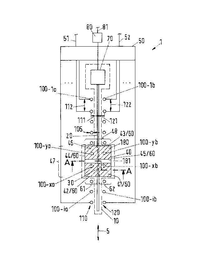
FIG. 1. shows schematically an operating device 1. The operating device 1
comprises a
=
. volume control 10. Along an adjustment path 20, a lever 30 of the volume
control 10 is linearly
= displaceable. In order tp be able to operate the lever 30 manually, the
volume control 10 has
an actuating element 40. Depending on the position of the lever 30 or of the
actuating element
40 along the adjustment path 10, a parameter signal is provided at an output
51 by a control
device 50: The position of the actuating element correlates with a parameter
value or a
volume control value.
The volume control 10 is preferably designed as a so-called motor volume
controller. In order
to be able to actively shift the lever 30 and the actuating element 40 thereon
to any desired
position along the adjustment path 20, such a volume control 10 has an
actuator 70 which
can move the lever 20 back and forth along the adjustment path 20. The
actuator 70 is
preferably controlled via the control device 50.
The actuating element 40 is mounted on the lever 30. The lever has at this
end, as a rule, a
T-shaped design. On this end, the actuating element 40 is preferably attached
by means of
a snap-in connection. The actuating element 40 has a top face 41, a front face
42, a back
face 43, a left face 44, a right face 45 and a bottom face 46, which faces the
plane of the
drawing. Those side surfaces of the actuating element 40, which can be touched
by a user
=
CA 3059103 2020-04-04
Apblication no. CA 3059103
Docket no.: P5029CA00
during a manual adjustment of the actuating element 40 along the adjustment
path 20, are
also referred to as gripping faces 60. Thus, the surfaces of the top face 41,
the front face 42,
the back face 43, the left face 44 and the right face 45 are the gripping
faces 60.
Adjacent to the adjustment path 20, along which the lever 30 of the volume
control 10 can be
displaced, a multiplicity of illumination means 100, 100-na, 100-nb is
arranged, (n is in each
case a counting index). The illumination means 100-na, 100-nb are each coupled
with the
control device 50 so that each of the illumination means 100 can be activated
individually or
adjustment path position-individually. In a variant in which an individual
control of the
illumination means 100 is possible, the control device can control each
individual illumination
means 100-na, 100-nb in such a way that this illumination means emits light or
does not emit
light. In an embodiment in which the activation occurs adjustment path
position-individually,
the control device can control the illumination means depending on their
position along the
= adjustment path 20. Illumination means 100-na, 100-nb, which have the
same position along
the adjustment path but are arranged, for example, on the different sides of
the adjustment
= path 20, can then be actuated together but separately from illumination
means at other
positions. In the illustrated embodiment an individual activation depending on
the position
along.the adjustment path means, that the illumination means are each
activated in pairs.
=
= Thus, an individual activation occurs for each position, but not
necessarily an individual
= activation of the illumination means 100 arranged at the same position
long the adjustment
.= path. An individual activation thus permits an even greater variety
of settings than an
adjustment path position-individual activation, in particular with regard to a
homogeneous
illumination, in particular transversely to the adjustment path. In preferred
embodiments, the
= control device 50 can also control the intensity of the emitted light
adjustment path position- =
individually for the illumination means 100. The number of required control
circuits is reduced
compared to individual control of each illumination means
Other embodiments may provide that also the illumination means arranged at the
same
position along the adjustment path can be controlled individually.
In the illustrated embodiments the illumination means 100 are divided into two
groups 110,
120 of illumination means 100. One of the groups 110 of illumination means 100-
na is
arranged on one side of the adjustment path 20, the other group 120 of
illumination means
100-nb is arranged on the opposite side of the adjustment path 20. (The
suffixed letters a
and b indicate a group affiliation or "side affiliation".) Within the groups
110,120, the
illumination means 100-na, 100-nb are each arranged spaced with regard to each
other along
the adjustment path 20. A longitudinal distance 112,122 of the illumination
means 100
11 =
CA 3059103 2020-04-04
Application no. CA 3059103 Docket no.:
P5029CA00
=
between two adjacent illumination means on the same side of the adjustment
path 20 is thus
the same for all illumination means of this side of the adjustment path 20.
The illumination means 100 each have an identical diameter 105 of the
illumination means.
In other embodiments, the diameter 105 of the illumination means may vary
slightly. The light
exit surfaces of the illumination means 100 are preferably as homogeneous as
possible,
which means similarly designed in shape, surface and texture.
The illumination means 100 are preferably multi-coloured illumination means,
which are also
referred to as coloured illumination means. This means that a single
illumination means is
able to emit light of different wavelengths. The illumination means 100 are
especially
preferably each designed as RGB LEDs. An RGB LED contains semiconductor
structures
that can emit light in the red, green and blue wavelengths region. By varying
the intensities
of the different wavelengths, it is possible to generate a plurality of
colours of la gamut (colour
space) due to the additive colour mixture. Depending on the different
intensity ratios of the
three emitted wavelengths or emitted spectra of the different semiconductor
structures, a
human observer perceives a colour from the gamut for the emitted light. The
colour of the
light perceived by a human observer can thus be adjusted via the control
dev(ce 50 for each
of the illumination means 100.
The actuating element 40 has a length 47 and a width 48. The length 47 of the
actuating =
=
element is measured parallel to the adjustment path 20 of the volume control
10, the width
48, however, perpendicular to the adjustment path 20 of the volume control 10.
An adjustment
direction 5 is oriented parallel to the adjustment path 20 and indicates the:
direction along
which the actuating element 40 and the lever 30 of the volume control 10 can
be moved back
and forth.
The width 48 of the actuating element 40 is adjusted to lateral distances 111
and 121 of the
illumination means 100-na or 100-nb to the adjustment path in a way, so that
the actuating
element 40 completely covers at least one illumination means 100 in each
position.
In the illustrated embodiment of FIG. 1, in which a group 110 of illumination
means 100-na is
. arranged on
one side of the adjustment path and the other group 120 of illumination means
: 100-nb on
the opposite side of the adjustment path, the actuating element 40 is formed
so
that the actuating element 40 completely covers several of the illumination
means 100 at a
time in each position along the adjustment path 20.
12
CA 3059103 2020-04-04
Application no. CA 3059103
Docket no.: P5029CA00
A width 48 of the actuating element 40 is thus adequately selected, that
illumination means
100-na on one side of a group 110 as well as illumination means 100-nb of the
opposite
group 120, are covered in any position along the adjustment path 20. A width
48 of the
actuating element is thus greater than a transverse distance of adjacent
illumination means
100-na, 100-nb on the opposite sides of the adjustment path. Projections 61,
62 of the
actuating element laterally beyond the lever 30 are thus greater in each case
than the sum
of a lateral distance 111, 121 and the diameter 105 of one illumination means.
In the illustrated embodiment, the length 47 of the actuating element 40 is
greater than the
sum of the double of the diameter 105 of the illumination means and the
longitudinal distance
112,- 122 of adjacent illumination means 100, which are each on the same side
of the
adjustment path 20 of the lever 30.
In the illustrated embodiment, at least two of the illumination means 100-na,
100-nb of the
two groups 110, 120 of the illumination means, are respectively covered on
each side of the
= = adjustment path 20 by the bottom face 46 of the actuating
element 40, which faces the plane
of the drawing. In the illustrated position of the actuating element, the
lighting means 100-xa,
100-ya, 100-xb, 100-yb are covered.
= The bottom face 46; which is facing the plane of the drawing, has a
coupling section 150. Via
==
. this coupling section 150 light, which has been emitted by the illumination
means 100, which
.
are covered by the bottom face 46 of the actuating element 40, can be coupled
into the
interior of the actuating element 40. In its interior, the actuating element
40 has a light guiding
section 160, which guides the light coupled in to one exit zone 170 or several
exit zones 170.
The exit zone 170 or the exit zones 170 are formed in the gripping faces 60 of
the actuating
element.
=
= In order to avoid glare by the illumination means 100, the control device
50 is designed in a
way, so that it only activates those illumination means 100 to emit light,
which are fully
covered by the actuating element 40. In the exemplary embodiment shown, these
are the
illumination means labelled with the reference symbols 100-xa, 100-ya, 100-xb,
100-yb. The
control device 50 is formed to deactivate the illumination means, which are
not covered, or
activate them in a way, so that they don't emit any light. Only those
illumination means 100
that are fully covered by the actuating element 40 are being activated to emit
light.
The illumination means 100 are preferably activated and adjusted by the
control device 50
so that they emit identically coloured light, when they emit light.
13
CA 3059103 2020-04-04
Application no. CA 3059103 = Docket no.: P50290A00
Other embodiments may provide that the colour of the respectively emitted
light is dependent
on the position of the respective covered illumination means along the
adjustment path 20.
In some embodiments, the actuating element is designed so that all gripping
faces are light
transmissive. In this case, the actuating element is illuminated from all
sides, as long as light
= is coupled in via the coupling section 150.
However, to avoid or reduce glare, especially in dark work environments, in
some
embodiments, at least a subarea of the top face and optionally additionally
the front face
and/or the back face and/or the left face and/or the right face of the
actuating element 40
provided with an opaque coating 180. At least on one of these sides; the
opaque cover, for
example in the form of an opaque coating 180, has a clearance 181 which serves
as an exit
zone 170.
In the illustrated embodiment, the exit zone 170 is designed as linear
clearance 181 in an
opaque coating 180, which means in an opaque cover, of the top face 41 of the
actuating
element 40. Light, which has been coupled into the actuating element 40 from
the bottom
face 46, thus exits the actuating element 40 from the clearance 181, which is
an exit zone
170. Thus, a bright luminous stroke appears on the top face 41 of the contrOl
element 40.
This is perceived in the colour which corresponds to the colour of the light
which is coupled
into the coupling section 150 by covered illumination means 100 and guided
through the light
guiding section 160 to the exit zone 170.
The linear clearance 181 can be used as a reading mark for a scale (not
shown), which is
optionally arranged next to the volume control.
The opaque cover 180 is preferably formed of a conductive material and
electrically
conductive connected with the lever 30 either in the interior of the actuating
element or along
the outer surfaces of the actuating element. This makes it possible to connect
a sensor 80,
which is called a contact sensor, to the volume control. This can detect the
contact of a user =
with the opaque cover. The sensor 80 preferably has a contact signal output
81, via which a
signal is provided which indicates the contact of a user. =
In alternative embodiments, the clear coating, which is transparent, may also
be made
conductive. Since the contact sensors can also partially evaluate a capacitive
coupling of a
body part to the actuating element 40 or a gripping face 60 of the actuating
element 40, the
14
CA 3059103 2020-04-04
Application no. CA 3059103
Docket no.: P50290A00
entire gripping face 60 of the actuating element does not have to be
electrically conductive
in each case in order to reliably detect every contact.
Preferably, at least one left face surface 144 and/or one right face surface
145 on the left
face 44 or the right face 45 may have an exit zone. For example, the left face
44 and/or the
right face 45 may be formed over the whole area as an exit zone. 'An advantage
of arranging
an exit zone on the left face and/or the right face 45 is that light exiting
at the faces 44, 45 or
the corresponding side surfaces 144, 145, can illuminate a part of an
operating interface (not
shown) or a part of scale, which is arranged hereupon. For this purpose, also
a light emission
from the front face and/or the back face of the actuating element 40 can be
used.
In order to ensure the correct activation of the illumination means 100, the
control device 50
is connected to the volume control 10 so that the control device 50 can
determine the position
of the actuating element 40 and the lever 30. This way it is possible to
select those illumination
means 100-xa, 100-xb, 100-ya, 100-yb which, in the current position of the
lever 30, are
=
covered by the actuating element 40 located thereon. These illumination means
100-xa, 100-
.
100-ya, 100-yb covered in the illustrated position are then activated to emit
light. A colour
; =
of the emitted light is preferably set by the control device 50 according to a
function
=
= associated with the volume control 10 and the operating strip of a mixing
desk in which the
= volume control 10 .is integrated. For this purpose, the control device 50
may have a function
input 52. Via the function input 52, the control device 50 can be provided
with, for example,
a function signal of an operating logic of a digital sound mixing console.
Based on the function
signal, the control device 50 then determines the assigned function. Depending
on the
assigned function, it is preferable to determine the colour of the light that
the illumination
= means 100 emits.
FIG. 2 shows a schematic sectional view according to the section line A-A of
FIG. 1. The
same technical features are provided in all figures with the same reference
numerals. On a
circuit board 200, the volume control 10 with the lever 30 is arranged as well
as illumination =
means 100 on both sides. An actuating element 40 is arranged on the lever 30.
This is made
in the interior of a diffusely scattering translucent material 240, which is
covered with a
translucent transparent, clear mater.ial layer 241 each at the bottom face 46,
on the top face
41 and on the left face 44 and the right face 45, respectively. This clear
material layer 241 is
optional on each of the sides. The bottom face 46 and the translucent areas
form the coupling
= section 150, which can be subdivided by the lever 30 into two coupling
section parts 150a,
150b. Guided light passes through the clear material layer 241 on the bottom
face 46 and
enters the diffusely scattering material layer 240. Due to the diffuse
scattering the light
CA 3059103 2020-04-04
Application no. CA 3059103
Docket no.: P50290A00
entering from below into the actuating element 40 is scattered in all
directions, so that light
emerges from all the surfaces of the diffusely scattering material 240 through
the clear
material layer 241.
= Only on those areas where an opaque cover, for example, formed as opaque
coating 180, is
applied, a light emission from the actuating element 40 is prevented. On a
bottom face, the
opaque cover may be formed to be reflective, to reflect the light back into
the diffusely
. scattering material 240. Alternatively or additionally to an opaque coating,
areas of the
actuating element 40 may also be made of opaque materials. However, it is
essential that a
light-guiding section 160 exists in the interior, which guides the light
coupled in at the bottom
face 46 to one of the outer surfaces, which means one of the gripping faces
60, of the
= actuating element and that an exit zone 170 is formed at least on one
outer surface, which
means on a gripping face.
In Fig. 2 can be clearly seen that the lever 30, which is usually made of a
metallic material
'and thus formed opaque, hinders or prevents a guiding of light between a left
half 244 and a
right half 245 of the actuating element 40. Therefore, in the illustrated
embodiment of Fig. 2
and-the embodiment of Fig. 1 respectively on both sides of the volume control
10, a group
. .
110,120 of illumination means 100 is arranged. Thus, a uniform illumination of
the volume
control, in particular of exit zones, which extend over the left half 244 and
the right half 245,
is possible.
However, other embodiments may also take advantage of this fact and form the
actuating
=
= element so that the left half and the right half are isolated from each
other with respect to the
guiding of light in the interior of the actuating element. Both, on the top
face as well as on the
= = front face and the back face differently coloured clearances in an
opaque cover can be
=
generated, as differently coloured light is coupled into the different halves.
This is achieved
by the fact that the one group of illumination means arranged on one side of
the volume
control emit light of one colour when they are covered by the control element
and the
illumination means on the other side of the volume control which belong to
another group of
illumination means, emit light of a different colour, if they are covered by
the actuating
element.
=
FIG. 3 shows a schematic side view of a side surface, for example the leftface
surface 144.
It can be seen that on the top face 41 a cover being formed as an opaque
coating 180 is
provided, which also extends over a part 380 of the side surface, which is
shown hatched. In
the opaque coating, a clearance 181 is formed in the form of a downward-
pointing stylized
arrow, which can be used as a reading mark. In the non-hatched areas of the
side surface
16
CA 3059103 2020-04-04
- Application no. CA 3059103 Docket
no.: P50290A00
light emerges from the actuating element 40 when light is coupled into the
actuating element
40 at the coupling section 150 at the bottom face 46.
In order to achieve the best possible illumination of an actuating element
with only one
illumination means or with two illumination means, which are arranged at the
same position
along the adjustment path 20, but on different sides of the volume control 10,
a central
coupling would be optimal with respect to the longitudinal direction of the
actuating element.
However, if the actuating element is displaced along the adjustment path
during actuation,
the coupling in posipon(s)of the light emitted by the illumination means
"wanders" or 'Wander
from the centre to4ard the front face or the back face, depending on the
shifting direction.
However, with light coupled in at the front face or. back face of the bottom
face, uniform
illumination of the t6p face, for example, is significantly more difficult or
impossible. Therefore,
it is provided in the preferred embodiment that always at least two
illumination means are
covered at the same time along the displacement direction or the adjustment
path, which are
therefore located at different positions with respect to the displacement
direction. Now these
can be activated differently with respect to their radiated light intensity,
so that in total the
most possible uniform illumination of the actuating element is achieved.
= .
In FIG. 4, light intensity control curves 401-404 are plotted against the
position P of the
actuating element, along the adjustment path for four illumination means
arranged
equidistantly on the same side of the adjustment path.
When the volume control is in the position P1, the illumination means 100-1 is
activated to
emit light of maximum light intensity 11. The remaining illumination means 100-
2-100-4 don't
emit any light in this position. If the volume control is moved to the
position P2, the intensity
11 of the illumination means 100-1 is attenuated and at the same time the
intensity 12 of the
illumination means 100-2 is increased. If the volume control -reaches the
position P3, then
light with maximum light intensity 12 is emitted by the illumination means 100-
2. When the
volume control is moved further in the direction of the position P4, the
intensity 12 of the
illumination means 100-2 is attenuated and now the intensity 13 of the light
source 100-3 is
increased. Depending on the position, the illumination means are thus
controlled differently
in order to achieve the most homogeneous possible illumination of the exit
zones of the
control element. The light intensity control curves shown here are only to be
understood as
=. examples. Other embodiments may have other forms. For example, more than
two light
sources along the adjustment path 20 can be covered by the adjusting element
40 at the
same time.
17
CA 3059103 2020-04-04
Application no. CA 3059103 Docket
no.: P5029CA00
= FIG. 5 schematically shows a plan view of a sound mixing desk 500. In an
operating interface
510 a plurality of operating strips 520-j are formed, each having a volume
control 10-j as well
as other control elements 530-j. In the operating interface slots 540-j are
present, which are
formed as clearance holes, in which the levers 30-j of the volume control 10-j
moves.
In the mixing desk shown different variants are shown. The slot 540-1 has such
a width
transversely to the adjustment path that the illumination means are arranged
in the area of
. the slot .optionally below the operating interface adjacent to the
volume control and still
illuminate the actuating elements located above the operating interface by the
coupling
surface formed l oFilhe bottom face thereof.
=
=
In the embodiMentil the remaining operating strips 520-2 to 520-4, the
illumination means
are embedded in the operating interface 510. The slots 540-2 fo 540-4 are
correspondingly
narrower,.
=
In the'figufesonly exemplary embodiments are described.
=
=
=
=
===;/,:'i=====?...s; =
. .; =
:;:.= = 1;.,.e
=
.=
=
= =
= =
=
= ,
=
=
= =
=
= = =
=
=
= 18
=
CA 3059103 2020-04-04
Application no. CA 3059103
Docket no.: P5029CA00
List of reference numbers:
1 operating device
adjustment direction
volume control
.20 adjustment path
30. lever
40 actuating element
41 top face
42 front face
43 back face
= 44 left face
45 right face
46 bottom face
47 length
48 width
50 control device
51 output
52 function input
60 gripping face
61 projection
62 projection
70 actuator
80 sensor
81 contact signal output
100 illumination means
100-nillumination means
100-na illumination means with index n of group a
100-nb illumination means with index n of group b
100-xa illumination means with index x of group a
100-xb illumination means with index x of group b
100ya illumination means with index y of group a
100yb illumination means with index y of group b
105 diameter of the illumination means
110 a group of illumination means
= 111 lateral distance illumination means- adjustment path
= 19
CA 3059103 2020-04-04
=
Application no. CA 3059103
Docket no.: P50290A00
112 longitudinal distance
.120 another group of illumination means
_121 lateral distance illumination means- adjustment path
122 left gap
150 coupling section
160 light guiding section
170 exit zones
180 opaque cover
181 clearance
200 circuit board
.240 diffuse scattering material
241 clear material
244 left half
=.= = ' ." 245 right half =
= 380 part
, 401- 404 light control curves
Pi Position i of the volume control
=
.500 sound mixing desk
= 510. operating interface
= 520-j operating strip j
,=
= 530-j control elements of the operating strip j
= .540-j slot of the operating strip j
=
=
=
CA 3059103 2020-04-04