Note: Descriptions are shown in the official language in which they were submitted.
CA 03059108 2019-10-03
WO 2018/187514 PCT/US2018/026144
Additive Manufacturing in Gel-Supported Environment
RELATED APPLICATION
[0001] This application claims the benefit of U.S. Provisional Application
No.
62/481,358, filed on April 4, 2017. The entire teachings of the above
application are
incorporated herein by reference.
BACKGROUND
[0002] Traditional manufacturing typically involves molded production of
parts and other
components having a fixed shape, and those individual components are
frequently assembled
into more complex structures. The process is often expensive and can involve a
significant
amount of manual labor, and molds used in the production are expensive to
manufacture and
have singular design structure.
[0003] Additive manufacturing refers to a collection of techniques for
making three
dimensional objects by layerwise addition of material. Stereolithography (SLA)
is an
additive manufacturing technique that involves selective photopolymerization
of polymers
upon exposure to UV light.
[0004] Selective laser sintering (SLS), direct metal laser sintering
(DMLS), and laser
melting (SLM) are additive manufacturing techniques that involve distributing
a thin layer of
a powder onto a substrate plate. In SLS and DMLS, a laser selectively sinters
the powder. In
SLM, a laser selectively melts the powder. Unlike SLA, which is typically used
with
polymers, SLS, DMLS, and SLS can be used with metals.
[0005] Fused deposition modeling (FDM), sometimes referred to as fused
filament
fabrication (FFF), an object is built by selectively depositing melted
material in a pre-
determined path layer-by-layer.
[0006] One problem with existing technologies is that they are too slow.
Another
problem with existing technologies is that manufacturing complex geometries,
such as
unsupported overhangs, can require fabricating a support structure that is
subsequently
removed during post-processing. Fabricating support structures often increases
the cost of
designing a part, and can lead to increased machine time to fabricate the
part. In addition,
- 1 -
CA 03059108 2019-10-03
WO 2018/187514 PCT/US2018/026144
some or all of the support structure is discarded, which increases the cost of
materials to
fabricate the part.
SUMMARY
[0007] The methods described herein pertain to additive manufacturing
techniques that
can be used to make three dimensional objects.
[0008] Described herein is a method of making a three-dimensional object.
The method
can include positioning a nozzle within a gel inside a container of gel;
changing the position
of the nozzle within the gel while depositing solidifying material through the
nozzle, whereby
the gel supports the solidifying material at the position at which the
solidifying material is
deposited; and solidifying the solidifying material to form a solid material,
the solid material
being a three-dimensional object.
[0009] Depositing the solidifying material through the nozzle can further
include varying
a rate at which the solidifying material is deposited, for example by varying
pressure applied
to one or more pistons to extrude the solidifying material. Changing the
position of the
nozzle within the gel can further include changing the position of the nozzle
at varying
speeds.
[0010] The nozzle can be affixed to a multi-axis machine. Changing the
position of the
nozzle through the gel can include moving one or more axes of the multi-axis
machine to
which the nozzle is affixed. Changing the position of the nozzle within the
gel can include
changing a position of the container of gel.
[0011] Solidifying the solidifying material can include exposing the
solidifying material
to light or heat. Solidifying the solidifying material can include allowing
the solidifying
material to cool. Solidifying the solidifying material can include exposing
the solidifying
material to light while depositing the solidifying material through the
nozzle.
[0012] The solidifying material can be a polymer, a rubber, a pulp, a foam,
a metal, a
concrete, or an epoxy resin. The rubber can be a silicone rubber.
[0013] The solidifying material can have a hardness between about Shore 00-
10 and
about Shore 90D when solidified.
[0014] The solidifying material can be a foam. The solidified foam can have
a density of
about 3 lb/fe to about 30 lb/fe.
- 2 -
CA 03059108 2019-10-03
WO 2018/187514 PCT/US2018/026144
[0015] The gel can be a suspension. The gel can include a carbomer or a
polyacrylic
acid. The gel can have a viscosity between about 20000 centipoise and about
50000
centipoi se.
[0016] The nozzle can have a circular-shaped, rectangular-shaped, square-
shaped,
diamond-shaped, V-shaped, U-shaped, or C-shaped tip through which the
solidifying material
is deposited.
[0017] The solidifying material can include two compounds that co-
polymerize.
Solidifying the solidifying the solidifying material can include allowing the
two compounds
to co-polymerize. The nozzle further include a mixing portion that mixes the
two compounds
as they are deposited through the nozzle.
[0018] Changing the position of the nozzle can include changing the
position of the
nozzle within the gel in three through eight axes simultaneously, for at least
a portion of time.
Changing the position of the nozzle can include changing the position of the
nozzle within
the gel in five through eight axes simultaneously, for at least a portion of
time. Changing the
position of the nozzle include changing the position of the nozzle within the
gel in three
through six axes simultaneously, for at least a portion of time. Changing the
position of the
nozzle can include changing the position of the nozzle within the gel in six
axes
simultaneously, for at least a portion of time.
[0019] Changing the position of the nozzle can include changing the
position of the
nozzle to deposit solidifying material onto, around, or within another object
within the gel.
[0020] The nozzle can be a first nozzle, the solidifying material can be a
first solidifying
material, and the solid material can be a first solid material. The method can
further include
positioning a second nozzle within the gel inside the container of gel;
changing the position
of the second nozzle within the gel while depositing a second solidifying
material through the
second nozzle, whereby the gel supports the second solidifying material at the
position at
which the second solidifying material is deposited, and whereby depositing the
first and
second solidifying materials is performed so that the first and second
materials contact each
other in deposited state; and solidifying the second solidifying material to
form a second solid
material, whereby the first and second solid materials are joined together as
the three-
dimensional object. The first and second nozzles can have tips with different
shapes. The
first and second solidifying materials can be different.
- 3 -
CA 03059108 2019-10-03
WO 2018/187514 PCT/US2018/026144
[0021] Described herein is an apparatus for making a three-dimensional
object. The
apparatus can include a nozzle affixed to a multi-axis machine; a means for
extruding a
solidifying material through the nozzle; and a container of gel.
[0022] The apparatus can be configured as described herein to perform the
methods
described herein.
[0023] The methods described herein confer a number of advantages. Notably,
the
methods are fast. Compared to other additive manufacturing processes, such as
FDM and
SLM, printing in a gel suspension in the disclosed embodiments of the additive
manufacturing methods and systems described herein can be much faster,
potentially orders
of magnitude faster, for printing parts with complex geometries, such as those
illustrated in
FIG. 4. In some instances, the methods may be 300x faster, or more, than
existing processes.
Since it is not necessary to deposit support structures, post-processing of a
manufactured
object is substantially reduced. For example, post-processing can simply
include washing the
object in water. It is not necessary to cut away or otherwise remove support
structures
manually. The methods can also be used to manufacture large objects. The size
of the
container of gel is the only factor that limits the size of the object that
can be manufactured.
[0024] Even though speed and size can be increased compared to known
techniques, the
manufactured objects are of a high quality. The solidifying materials that can
be used in the
methods described herein can be industrial-grade materials. For example, the
methods
described herein can be used to fabricate objects with silicone rubbers,
whereas other
methods may require the use of elastomers that are not truly silicones. The
methods can also
be used to fabricate materials from foams. The methods can also be used to
fabricate
materials from rigid polymers, whereas other methods may require sintering
powders, and the
resulting objects may have inferior mechanical properties. Since the methods
described
herein do not require layer-by-layer deposition, the objects that are formed
do not have
stratified layers, which can be mechanically inferior to a product that is
formed of a
homogenous cross-section.
BRIEF DESCRIPTION OF THE DRAWINGS
[0025] The foregoing will be apparent from the following more particular
description of
example embodiments, as illustrated in the accompanying drawings in which like
reference
- 4 -
CA 03059108 2019-10-03
WO 2018/187514 PCT/US2018/026144
characters refer to the same parts throughout the different views. The
drawings are not
necessarily to scale, emphasis instead being placed upon illustrating
embodiments.
[0026] FIG. 1 illustrates a 3-axis gantry-style machine with a 2-part
mixing deposition
system printing a 3-dimensional part in a gel suspension.
[0027] FIG. 2 illustrates a 6-axis robotic arm with a two-component mixing
deposition
system printing a 3-dimensional part in a gel suspension.
[0028] FIG. 3 illustrates the deposition system with two-component
solidifying material
that is pneumatically controlled to flow through the mixing tip for thorough
mixing and
extrusion out the nozzle.
[0029] FIG. 4 illustrates a comparison between different printing processes
for the same
diagonally-shaped part.
[0030] FIG. 5 illustrates a variety of nozzle geometries, sizes and the
resultant printed
path.
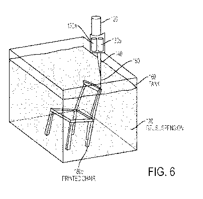
[0031] FIG. 6 illustrates a large tank of the gel suspension medium that
prints a full-scale
chair, suspended in 3D space.
[0032] FIG. 7 illustrates a printing portions of a chair onto and/or around
a metal frame
inserted into a large tank.
DETAILED DESCRIPTION
[0033] A description of example embodiments follows.
[0034] As used herein, the term "gel" refers to a colloid in which
particles are dispersed
in a liquid medium. Most commonly, the dispersed particles are cross-linked
particles. The
gels can be thixotropic. Most gels are predominantly liquid by weight, but
exhibit solid-like
material properties due to the three-dimensional cross-linked network within
the liquid.
[0035] The methods described herein pertain to a method of additive
manufacturing
within a gel suspension environment. Typically, the gel is held within a
container. A
solidifying material, which can be a molten or liquid form, is deposited with
through nozzles
and tool paths.
[0036] In some embodiments, a multi-axis machine be used to control a path
of a nozzle
through the gel. Examples of a multi-axis machines include gantry-type systems
and
industrial robot arms. In general, a wide variety of multi-axis machines and
robotic arms are
available. Gantry-style machines typically provide for three axes of movement:
the x-, y-,
- 5 -
CA 03059108 2019-10-03
WO 2018/187514 PCT/US2018/026144
and z-axes. Frequently, robotic arms are described according to the number of
axes of
rotation the arm possesses. For example, a five-axis robotic arm can rotate at
five distinct
axes of rotation, and a six-axis robotic arm can rotate at six distinct axes
of rotation. In
additional to rotational axes, a robotic arm can also be affixed to a linear
rail or gantry-style
machine to provide linear axes of movement in addition to the rotational axes.
As an
example, a six-axis robotic arm affixed to a linear rail can move in seven
axes. As another
example, a six-axis robotic arm affixed to a gantry-style machine can move in
seven, eight, or
nine axes, depending on the particular movements of the gantry-style machine.
[0037] In addition to axes of movement provided by a multi-axis machine,
the container
holding the gel can also be moved. For example, the container of gel can be
placed on a
multi-axis gantry-style machine, which can move the container of gel in three
axes that are
separate and distinct from axes of movement of the multi-axis machine to which
the nozzle is
affixed. The container of gel can also be moved along a rotational axis as
well.
[0038] In some embodiments, the container of gel moves along one axis and
the nozzle
moves along two axes. In some embodiments, the nozzle is stationary, and the
tank moves
along two or three axes. In some embodiments, the tank is controlled by a
gantry-style
machine
[0039] In some embodiments, the nozzle is controlled by a winch robot,
which can also
be referred to as a cable robot. In these embodiments, a plurality of cables
control movement
of the nozzle in the x-, y-, and z-directions.
[0040] The combination of these components allows for extremely fast
printing with a
variety of materials. For example, molten polymers can be deposited through
the nozzle and
solidified. For example, curing can include polymerization, which can be
photoinitiated. In
other embodiments, a polymer can be heated to accelerate a polymerization
reaction rate.
Chemically-cured, photo-cured or air/water-cured plastics, rubbers, foams and
other liquids
can be printed at large-scales only limited by the size of the container or
robotic apparatus.
Different nozzles can be used to control the flow rate, size, direction and
cross-sectional
geometry. Similarly, complex 3-dimensional tool paths can be created to print
in any
orientation and direction in 3D space.
[0041] Existing additive manufacturing processes have had limited
industrial applications
due to their lack of speed and size compared with other industrial
manufacturing processes.
The methods described herein can increase the speed of printing by using a gel
suspension
- 6 -
CA 03059108 2019-10-03
WO 2018/187514 PCT/US2018/026144
that does not require support materials nor slow printing speeds while waiting
for the material
to harden, like other 3-dimensional printing processes. Manufacturing speed is
also increased
because the objects are not produced layer-by-layer, as in other additive
manufacturing
processes (e.g., FDM, inkjet-like printing using liquid binder and powder
(e.g., as available
from ZCorp, acquired by 3D Systems), SLA, SLS, and Polyj et printing (e.g.,
CONNEX
printers available from Stratasys Ltd)) that require excessive time to print
large structures.
Rather, parts can be printed in three-dimensional space.
[0042] FIG. 4 illustrates a comparison between different additive
manufacturing printing
process for the same diagonally-shaped part. In FDM printing, the part is
divided into
horizontal slices, and there is a horizontally sliced support region printed
to support the
overhanging portion. In SLA printing, the part is sliced horizontally and
small vertical
supports are printed to support the overhanging portion. In a powder-based
system (e.g., SLS
or ZCorp), the part is sliced horizontally and the surrounding powder supports
the
overhanging portion. In the gel-supported environment methods described
herein, the part is
printed directly in the orientation of the component, without horizontal
slicing, effectively
increasing the speed of printing and structural continuity of the part, and
the surrounding gel
acts at the support material.
[0043] Post-processing time is also dramatically decreased because supports
structures
are not necessary. Traditionally, these support structures are manually
removed or dissolved.
In the method, printing time is only limited by the speed of the machine and
curing time of
the deposited solidifying material (from seconds to hours depending on the
composition).
[0044] The scale of printing can vary. Extremely small scale structures
with fine features
can be made by using a smaller nozzle tips. Larger structures with larger
features can be
made by using a larger nozzle.
[0045] FIG. 1 is an illustration of a three-axis gantry-style machine 100
used with a two-
part material. An arm 110 is affixed to the gantry system 100 such that the
arm can be moved
in the x-, y-, and z-axes, as indicated. In this particular embodiment,
pneumatic deposition
can be provided through pneumatic control system, which includes a chamber 120
for
exerting force on pistons 126a and 126b (see FIG. 3). Two chambers 130a and
130b are
provided that hold two different materials. These materials are mixed in
mixing tip 140 and
deposited through nozzle 150. Container or tank 160 holds a gel 170. As arm
110 moves,
nozzle 150 moves through the gel and the two materials are extruded into the
gel from
- 7 -
CA 03059108 2019-10-03
WO 2018/187514 PCT/US2018/026144
chambers 130a and 130b to form three dimensional object (printed part) 180a.
FIG. 2 is an
illustration of a six-axis robotic arm 200 with a two-part material. The
remainder is
substantially similar to FIG. 1.
[0046] FIG. 3 is an illustration of a deposition system for a two-part
material that is
pneumatically controlled to flow through the mixing tip. Air enter through
tube 124, passes
through pressure regulator 122, and enters into chamber 120, whereby the air
provides a
downward force on pistons 126a and 126b to force material out of chambers 130a
and 130b,
respectively. A solidifying material (e.g., a liquid) 180b is extruded through
the nozzle tip
150.
[0047] As an alternative to the pneumatic deposition illustrated in FIG. 3,
an electrically-
activated screw deposition system can be used. For example, a motor can be
used to exert
downward force on pistons 126a and 126b.
[0048] FIG. 6 is an illustration of use of the methods described herein to
make a chair
180c.
[0049] 1. Deposition of Solidifying Materials
[0050] 1.1. Materials
[0051] The methods described herein use a deposition system to deposit
solidifying
materials of varying quantities and viscosities. The methods are unique
compared to other
additive manufacturing processes because they allows for easy liquid material
flow/deposition, faster printing speeds and the use of industrial-grade
materials. In some
embodiments, the solidifying material is a single component. In other
embodiments, the
solidifying material is two separate compounds that co-polymerize.
[0052] To date, a variety of plastics, foams and rubbers that are either
one-part or two-
part air-cured or chemically-cured materials have been tested. Most other
processes rely on
powder material with adhesive binders, powders with selective sintering, UV-
curable
polymers or hot-end filament extruders which inherently limit the materials
available and the
final material properties of the printed structures. The methods described
herein can be used
to print with industrial-grade materials, such as polyurethane (PU) rubber,
foam and plastics,
resins, silicone, biological materials, liquid wood pulp, concretes, liquid
metals or any other
solidifying material, which greatly broadens the possibilities for industrial
printing
applications.
- 8 -
CA 03059108 2019-10-03
WO 2018/187514 PCT/US2018/026144
[0053] Examples of foams include urethane and silicone foams. As used
herein, foam
refers to a material having trapped pockets of gas in a liquid or solid. Foams
are typically
deposited in a liquid form, and then solidified.
[0054] Examples of plastics include chemically-cured plastics, such as
urethanes,
acrylics, and poly(methyl methacrylate), as well as radiation-cured plastics
and moisture-
cured plastics.
[0055] Examples of resins include epoxy resins, phenol-formaldehyde resins,
anaerobic
resins, and cyanoacrylates.
[0056] Examples of silicones include addition and condensation-cured
silicone rubbers
with a hardness ranging from Shore 00-10 to Shore 60A when solidified.
[0057] Examples of urethane rubbers include materials with a hardness of
ranging from
Shore 10A to Shore 90D.
[0058] Examples of biological materials include bacteria, antibodies,
lignin, growth
media, yeast, cellular matrices, eukaryotic cells, non-eukaryotic cells,
fungal medium,
seed/plant growth.
[0059] Examples of liquid wood pulp include cellulose, lignin and other
paper fiber
mixes with both natural and synthetic fibers.
[0060] Examples of concretes include Portland cement or other hydraulic
cements that
harden due to a chemical reaction with water.
[0061] Examples of liquid metals include metals and alloys that have a
melting point
below about 100 C, such as field's metal, wood's metal, and rose's metal.
[0062] The methods do not require layer-by-layer deposition. Rather, the
nozzle can
move and extrude in any orientation in 3-dimensional space. As a result, the
final printed
product can have a much stronger and more uniform material consistency and
surface finish
than products resulting from layer-based printing processes.
[0063] 1.2. Deposition
[0064] The methods described herein can use a syringe-type nozzle having an
opening
with a wide variety of shapes and sizes. The methods can also use a two-part
liquid extruder
that can extrude input materials at a ratio of 1:1, 2:1, 1:2, or other ratios.
The nozzle sizes and
shapes can accommodate different viscosities and different extrusion shapes or
features sizes.
For example, a more viscous material may require a larger nozzle and a higher
pressure while
a less viscous material can use a smaller nozzle and lower pressure. The
extrusion pressure
- 9 -
CA 03059108 2019-10-03
WO 2018/187514 PCT/US2018/026144
can be created with either pneumatics or mechanical actuation. Both actuation
techniques can
be controlled to precisely deposit the desired amount of liquid, stopped to
eliminate residual
liquids from extruding, or even potentially reversed to remove material in a
form of physical
deletion. The nozzle size can also increase the feature size of the printed
part and allow for
increased resolution, or increase the material quantity and speed to decrease
the resolution.
The speed of the deposition, size of the nozzle and the pressure in the
cylinder are interrelated
process variables. For example, to print faster, either the nozzle size or the
pressure can be
increased; otherwise, the volume of the material extruded per unit distance
traveled by the
nozzle decreases as the nozzle speed increases. in other words, varying the
nozzle size or
applied pressure can influence that rate at which the solidifying material is
extruded through
the nozzle, and therefore the rate at which the solidifying material is
deposited. The shape of
the nozzle opening can also vary to create different effects in the printed
part, resembling a 3-
dimensional calligraphy technique. Nozzles having circular-shaped, square-
shaped,
diamond-shape, V-shaped, U-shape, C-shape or virtually any other shape nozzle
can be used
to create different feature profiles. Examples of nozzle shapes are
illustrated in FIG. 5. Any
of the components can be used interchangeably in the system, or
simultaneously. For
example multiple nozzles can be used simultaneously to deposit two different
materials at the
same time. Or, different nozzles can be swapped out with a tool-changer to
allow for the
creation of a single, complex design with different feature sizes, materials
and/or profiles.
[0065] A mixing tip 140 can also be used to thoroughly mixes a two-part
solidifying
material for chemical curing. The liquid materials can have a variety of cure-
times from a few
seconds to minutes or hours. The liquid material can also have a variety of
final-cured
properties such as high stiffness (e.g., acrylonitrile butadiene styrene (ABS)
plastics);
elasticity (e.g., rubbers); expanding, flexible, or rigid foams; solubility
(liquids); brittleness;
high-temperature resistance, or theoretically any other property. The liquids
can also be
virtually any color and viscosity with the use of fillers and color additives.
All of these
properties can be varied with independent cartridges, continuous-fill
mechanisms to change
the properties on-the-fly, multiple-nozzles for multi-material printing or
tool-swapping to
allow for different materials in different locations.
[0066] 2. Gelatinous Printing Media
[0067] 2.1. Composition
- 10 -
CA 03059108 2019-10-03
WO 2018/187514 PCT/US2018/026144
[0068] A gel is used as the media within which the solidifying material is
deposited.
When the solidifying material is deposited, the gel supports the solidifying
material such that
the solidifying material is suspended within the gel.
[0069] A wide variety of gels are suitable. One particular example of a gel
that has been
used is a neutralized polyacrylic-acid (carbomer 940) gel. Between 1% and .25%
by weight
of carbomer 940 is thoroughly mixed in water such that no clumps remain. At
this point the
mixture has a low viscosity and a low pH. A solution of sodium hydroxide
(NaOH) in water
is incrementally added to the carbomer mixture and slowly stirred as to avoid
air bubbles
until the pH is neutralized. At this point the mixture transforms into a thick
gel.
[0070] Adjusting the pH can adjust the viscosity of the gel, which allows
the gel to
accommodate and support objects of differing density, as discussed in the
following section.
[0071] Adjusting the viscosity of the gel also influences how the nozzle
passes through
the gel as well as features of the printed structure. For example, if both the
gel and
solidifying material have a low viscosity, then the solidifying material may
not remain in
precisely the location where it is deposited. Increasing the viscosity of the
gel can ensure that
the deposited solidifying material remains within the path where it was
deposited rather than
flowing through the gel. Alternatively, in some embodiments, the viscosity of
the solidifying
material can be increased if the viscosity of the gel is too low.
[0072] 2.2. Controlling Buoyancy of Objects
[0073] The amount of carbomer 940 used in the gel affects the subsequent
suspension of
foreign materials, liquid or solid.
[0074] A higher percentage of carbomer results in a gel with higher
viscosity and shear
stress. In this condition the gel is able to suspend materials with densities
much lower or
higher than its own. At a rate of 1% carbomer by weight, the gel is able to
suspend a 1/4 inch
lead sphere.
[0075] A lower percentage of carbomer results in a gel with lower viscosity
and shear
stress. In this condition the gel is unable to suspend materials with
densities much lower or
higher than its own. At a rate of .25% carbomer by weight, the gel is unable
to suspend a 1/4
inch aluminum sphere.
[0076] The gel composition can be modified so that it is suitable for
formation of the
desired object. Typically, the gel can have a viscosity between about 20000
centipoise (cP)
and about 50000 centipoise (cP).
- 11 -
CA 03059108 2019-10-03
WO 2018/187514 PCT/US2018/026144
[0077] 2.3. Self-Healing
[0078] A gel can self-heal in that after the nozzle passes through the gel,
the gel reforms
to close the gap in the void area where the nozzle has passed. As a result,
air pockets within
the gel are minimized. A lower shear stress (slower nozzle speed) permits the
gel to self-heal
quickly as the nozzle passes through. As a result, deposition of solidifying
material in lower
viscosity gel better maintains the form of the deposition nozzle orifice. High
viscosity gel
requires more time to self-heal. As a result, liquid material is able to flow
into the cavity left
by the tool before the gel is able to self-heal. This effectively elongates
circular depositions
into a teardrop shape. Thus, the shape of the liquid material varies in
proportion to relative
viscosity of the gel and speed of the nozzle passing through.
[0079] 3. Fabrication Machine
[0080] 3.1. Gantry-System
[0081] The liquid extrusion process within the gel suspension can be
precisely controlled
with at least a three-axis CNC machine. With a three-axis, gantry-style
machine, the cartridge
and nozzle are attached to the Z-axis, and three-dimensional structures can be
printed within
the gel. The nozzle can move freely in all three linear dimensions (x-, y-,
and z-dimensions),
however the nozzle cannot rotate around the z-axis (when used on a 3-axis
machine).
Typically, the printed part is constrained to 3-dimensional geometries with
vertical nozzle
orientations.
[0082] A five-axis gantry-style machine can also be used. In a five-axis
machine, the
nozzle can move in all three linear dimensions (x-, y-, and z-dimensions), as
well as rotate on
the A- and B-axes. Since the nozzle can rotate, the solidifying material does
is not
necessarily dispensed from a vertical orientation.
[0083] 3.2. Industrial Robot Arm
[0084] In other embodiments, a six-axis industrial robot can be used to
move the nozzle
through the gel. Typically, a six-axis industrial robot allows for rotation
along six different
axes. As a result, the nozzle can be oriented in a wide variety of directions,
allowing for
printing sideways or rotating the nozzle as it moves in space. Similarly,
greater freedom over
the orientation of the robot and the relationship to the printing axis is
allowed.
[0085] 3.3. Other Machines
[0086] Other deposition machines are also possible like "delta" robots,
cable bots, or
even distributed printing processes with autonomous robots. This process does
not require an
- 12 -
CA 03059108 2019-10-03
WO 2018/187514 PCT/US2018/026144
extremely specific machine, rather it can accommodate just about any computer
numerically
controlled (CNC) machine that can move in three dimensions with multiple axes
of control.
[0087] 3.4. Scale
[0088] Both of these methods can be scalable to large (many cubic meters)
or small
(cubic millimeters) print volumes with either high precision and/or high-speed
depending on
the application. If a small part with high precision is needed, a gantry-style
machine can be
used with extremely precise syringe tips in a small gel volume. Conversely, if
a very large-
scale structure is needed, a large gantry-machine (10's of meters), or large
industrial robot (5
meters +) can be used. Theoretically there is no limit to the size of the
machine, however a
large gel-bath is required and as the scale increases, the amount of gel
required and the size of
the container increases. For industrial products on the order of millimeters
to multiple meters,
this process is very viable and may provide an extremely fast and precise
printing process
with industrial-grade materials.
[0089] 3.5. Speed & Multiple Machines
[0090] The outlined fabrication machines can operate at slow speeds or fast
speeds,
depending on the application, the time constraint or the features of the
printed part. Typically,
the robot arm controlling the nozzle will need to move more slowly for smaller
parts and for
smaller features of a part. For larger parts and larger features of parts, the
robot arm
controlling the nozzle can move more quickly. Alternatively, multi-robot
printing processes
can be used where large features are created with one arm and smaller features
are created
simultaneously with another arm. This can also allow for different materials
or interlocking
parts, or other features that would not be feasible with a single machine.
[0091] 4. Speed
[0092] 4.1. Support Material
[0093] The present invention can be far faster than existing printing
process for a number
of reasons. The first element that dramatically increases speed is the
elimination of extra
design material for support. Since the viscous gel can support the deposited
material, there is
no need for a printed support material like FDM, SLA or many other processes.
This
dramatically decreases the amount of material that needs to be printed, the
time it takes to
print, and also the time to remove the excess material from the printing. For
example, a
diagonal part with overhanging features can be printed directly in 3-
dimensional space
without the need for a support wall or column.
- 13 -
CA 03059108 2019-10-03
WO 2018/187514 PCT/US2018/026144
[0094] By removing this limitation, extremely complex structures can also
be printed that
would not otherwise be possible with other printing processes that require
supports. For
example, a structure that is hollow, but has a complex shape within the hollow
cavity would
be difficult to build in other processes because the support material would
need to fill the
cavity of the printed part and span from one printed part to another. This
extra material may
not be possible to remove and may limit the possible complexity of the shape.
In an SLA or
powder-based printing processes, sometimes the support material can be trapped
within the
cavity and dramatically increase the amount of material that a part requires.
[0095] 4.2. Post-Printing-Process
[0096] By printing with chemically or air-cured solidifying materials
within a viscous
gel, the methods described herein reduce or eliminate complex and time-
consuming post-
processing. SLA printing processes typically require a support removal step,
which can
require manually breaking off the support structures. There is also a cleaning
process in an
alcohol bath to remove the uncured polymers. These steps can be potentially
toxic, costly and
extremely time consuming. FDM and Polyj et printing typically involve a
support-dissolving
step, where the part is put in a bath to remove the support material. This can
also be toxic and
extremely time consuming. After printing a part for many hours, it then needs
to sit in a bath
for many minutes or hours while the supports are removed. In powder-based
printing
processes there is an excavation process that is very messy and time consuming
where the
user needs to dig out the part from the powder bath. With the methods
described herein, when
the part is printed it can be immediately cured (or time-delayed depending on
the material
selection), and then it can be immediately removed from the gel by simply
reaching in and
taking out the part. The part can then be simply sprayed with water to remove
the excess gel
and it is finished, ready for use. This simple post-printing-process can
dramatically increase
the application of 3D printing in industrial settings, reduce the hazards and
allow for printing
to become more accessible to a wider audience and increase the speed of the
post-process.
[0097] 4.3. Layer Printing vs. Spatial Printing
[0098] With the spatial liquid deposition in the viscous gel media, any
complex structure
can be printed directly in three-dimensional space without slicing and layer-
based printing
software file preparation steps.
[0099] In contrasts, layer-by-layer processes requires fairly complex
software and
produce large file sizes. The slicing process also frequently increases the
failure-rate or the
- 14 -
CA 03059108 2019-10-03
WO 2018/187514 PCT/US2018/026144
surface roughness of the printed part. Because the complex 3-dimensional model
needs to be
algorithmically reconstructed with 2-dimensional paths, features can be left
out, the path can
be incorrect or it can reduce the resolution of the part due to the layer-by-
layer material
texture. Similarly, this layer-by-layer process dramatically decreases the
strength of the
printed part due to inhomogeneity. The methods described herein do not have a
layer-by-
layer printing process and can create completely homogenous cross sections
within a printed
path in any orientation in 3-dimensions.
[00100] Similarly, in the methods described herein, a printed part can be
extremely fast to
print as compared with layer-by-layer processes. With layer-by-layer printing,
the time of
printing can be calculated by the linear length of each 2-dimensional path
times the number
of z-height slices. This dramatically increases the time it takes to print
each layer. In our
process the nozzle can print in any orientation with any feature size and does
not need to print
layer-by-layer, dramatically increasing the speed and feature possibilities of
a printed part or
object.
[00101] 5. Usage
[00102] 5.1 Printing in three-dimensional space
[00103] The methods described herein allows for objects at small or large
scales to be
printed reminiscent of 2-D drawing or sketching yet in 3-dimensional space. In
some
embodiments, the nozzle can be manually moved through the gel by hand without
aid of a
multi-axis machine. In some embodiments, the robotic arm or gantry-style
machine can be
manually moved through the gel by hand. Manual movements of the robotic arm or
gantry-
style machine can be recorded by software as the arm or machine are moved,
thereby creating
a recording of a movement that can be replayed for future automated
production. In other
embodiments, the gantry-style machine or robotic arm can be controlled with a
controller.
[00104] In some of the methods described herein, the structure to be
fabricated can be sent
to the robot arm as a curve in 3D space. As an example a three-dimensional
curve can be
generated in modeling software. The curve can be exported as a series of
points in 3D space
that the machine will follow during the printing process. The output of the
modeling software
is typically in machine code (e.g., Gcode, ShopbotCode, URCode, or a variety
of other types
of code files linked with the specific CNC machine that is being used). This
process
eliminates the need to use an STL file (or mesh geometry file) that is usually
exported from
modeling software and subsequently imported into a slicing software that
slices the
- 15 -
CA 03059108 2019-10-03
WO 2018/187514 PCT/US2018/026144
STL/Mesh geometry into layers that create tool paths for the machine to
follow, layer-by-
layer. The slicing software generates the machine code for a typical printer.
In methods
described herein that involve the use of a multi-axis machine, the slicing
step is not
necessary, and the machine code is generated from a series of 3-dimensional
points in space
based on the original 3D curve. The machine code can include other parameters
and values.
For example, the machine code can include parameters that increase or decrease
the air
pressure (e.g., to turn the air pressure on or off); to adjust the speed of
the machine (e.g., to
adjust the speed of the nozzle as it is moving through the gel); and to adjust
the orientation of
the nozzle as the machine moves the nozzle through the gel.
[00105] When connected with design software, a modeling tool or VR headset,
the
methods described herein can allow for a designer to sketch and design in mid-
air while
simultaneously printing at the same speed and same scale, within the gel. This
1:1 design to
production speed and length-scale has not been realized before due to time
constraints
inherent with physical fabrication. Most fabrication processes, even for quick
sketch models,
take significant amounts of time and therefore cannot be as fast as sketching.
With this
technology a printed part can be created at the same speed that a robot or a
human moves
their arm through the air.
[00106]
[00107] 5.2 Printing onto Other Objects
[00108] If the fabrication machine (gantry or robot) picks up a physical
object and places it
into the gel, the machine can then liquid print onto, around or within the
physical object. This
capability allows for sequential printing of materials with a variety of
properties in one build.
Using the fabrication of a chair as an example, a structure (in this case, a
metal structure)
produced by another fabrication process can be placed within the gel. The back
of the chair,
which typically is made of a soft rubber material, can be printed around the
placed metal
structure. Next, the robot can switch to printing a foam material as the seat
cushion of the
chair, connected directly to the metal structure. This process can incorporate
fastener details
like screws, bolts or other connectors and can allow for hybrid fabrication
processes. Many
physical objects (flexible or rigid) with different materials can be deposited
or placed within
the gel acting as substrates for further build processes. Even a textile can
be placed in the gel
and printed onto.
- 16 -
CA 03059108 2019-10-03
WO 2018/187514 PCT/US2018/026144
[00109] FIG. 7 is an illustration of using the methods described herein to
fabricate a chair.
A metal frame 190 can be placed into the tank 160 of gel 170. The printed
chair cover and
frame 180d can be printed onto and/or around the metal frame 190 to produce
the spanning
flat surfaces of the chair. This process allows for hybrid printing scenarios
incorporating
other parts (e.g., industrially-produced parts) in the gel suspension.
[00110] 5.3 Cure-time
[00111] The printed solidifying material can be designed to cure extremely
quickly or
slowly, depending on the application. A faster cure time can reduce the
overall fabrication
time while a slower cure time can allow for more thorough bonding when
printing
intersecting paths. A slower cure-time can also enable bonding of the liquid
printed structure
with physical objects that have been placed into the gel
[00112] 5.4 Complex Tool Paths
[00113] Another potential advantage of this technique is the possibility of
fully
interlocking, 3-dimensional parts being made without support material or
filled cavities. For
example, printing a woven or knit structure may now be possible utilizing
multiple robots
that deposit liquid simultaneously, or by complex tool paths that would
otherwise not be
possible. With a 6-axis industrial robot, complex tool paths can be used,
almost like
calligraphy, with different nozzle extrusion orientations. Another possibility
is printing
underneath, next to or on top of other printed/physical objects within the
gel.
[00114] 5.5 Post-Process
[00115] Different forms of post-curing can be incorporated such as UV- or
temperature-
sets to change the properties of the material. After removing the part from
the gel bath, it can
be easily washed-off with water to remove excess gel, or coated with some
material to
strengthen it, color the part, further cure the part or any number of post-
processing
capabilities. For example, if a ceramic material is printed within the gel, or
a slurry of wood
or metal, the printed part may cure within the gel, then be removed and placed
into an oven
for post-processing. Such a capability can greatly increase part strength,
such as through a
post-printing firing or sintering processes as used in ceramics and metal
production, or a
number of other interesting material capabilities.
[00116] 5.5 Material Usage
[00117] Due to the removal of printed support material and the truly 3-
dimensional nature
of this printing process, much less material can be used for a printed part.
This process does
- 17 -
CA 03059108 2019-10-03
WO 2018/187514 PCT/US2018/026144
not require baths or beds full of powder or liquid resins. Similarly, the
layer-based process
and built-up printed support materials are quite wasteful in the total amount
of material used
compared with the material needed for the final part. In the methods described
herein, it is not
necessary to waste material.
[00118] 6. Advantages & Improvements over Existing Methods
[00119] This technology offers significant improvement over existing methods
of three-
dimensional printing, including; SLA, SLA, FDM, Polyj et and powder-based
printing. To
date, three-dimensional printing has not made a significant impact in
industrial manufacturing
processes because of: 1) long printing times compared with injection molding
or other
manufacturing processes; 2) relatively small build volume limiting realistic
applications; and
3) the availability of only low-quality printable plastics and other
materials, the properties of
which do not compare with industrial materials. The methods described herein
dramatically
improve upon each of these areas.
[00120] Since the methods described herein do not require support material to
build
overhangs or complex 3-dimensional structures, the structure can be made
significantly
faster. FDM, Polyj et and SLA technologies require supports that significantly
increase the
time required to print and the time after printing due to the need to remove
the supports either
manually or through dissolution. Without supports, the methods described
herein can print
the same complex three-dimensional shapes at the same time as reducing the
need for
additional unnecessary material, unnecessary time for printing and unnecessary
post-printing
processes. Once a structure is printed and the solidifying material solidifies
(e.g., cures), the
structures can be removed from the gel, simply washed off with water, and then
they are
finished. The methods utilize the gel's material structure to suspend the
print in 3-
dimensional space and allows for non-layer-based printing where the nozzle can
move freely
in all 3 axes at any time.
[00121] This technology also drastically increases the speed of printing by
eliminating the
requirement to print in successive layers. Nearly every printing process
available today
requires individual layers to be printed, layer-after-layer. This drastically
increases the time
required to print a tall or complex 3-dimensional form and requires
sophisticated digital
"slicing" techniques, producing large file sizes. For example, if a wireframe
structure was to
be printed using FDM, SLA, SLS, powder-based printing or polyj et, it would
need to be
sliced with many layers and then printed in linear paths at each layer. The
edges of the
- 18 -
CA 03059108 2019-10-03
WO 2018/187514 PCT/US2018/026144
wireframe structure would also need to have support material printed
underneath due to their
cantilever and unsupported shape. In the methods described herein, these lines
can simply be
drawn in three-dimensional space, eliminating the support material and
eliminating the slices.
Another aspect that increases the speed of printing compared to other free-
form or in-air
three-dimensional printing processes is the speed of extrusion. Other
processes require that
the material be cured or hardened before the machine moves to the next layer
or continues to
move the nozzle. This drastically decreases the speed at which the robot or
printer can move.
In the methods described herein, the material is suspended in the gel in three-
dimensional
space, and therefore the nozzle can continue moving quickly and extruding
materials that are
suspended behind the nozzle path and solidified (e.g., chemically cured).
Because of these
factors, the speed of printing can likely be increased by many orders of
magnitude compared
to traditional printing processes.
[00122] As compared with traditional methods of 3-dimensional printing, the
methods
described herein are also scalable from very small-scale, high resolution to
large-scale. Since
the process is dramatically faster than any other methods, much larger
structures can be built
in less time. For example a 6"x6"x6" cube of material may require 24-48 hours
to print on an
SLA machine while it can take a few minutes in the methods described herein.
The methods
can also scale-up by using larger tanks of gel and larger industrial robots or
gantry machines
and allow very large structures to be produced extremely quickly. The speed
and scale of the
print may now be able to be compared with other industrial processes like
injection molding
or machining. Especially if the assembly time of a traditional product is
taken into
consideration, the methods described herein, which may not require any
assembly since the
entire product can be printed simultaneously, may drastically change
manufacturing
scenarios.
[00123] One of the most significant advances over traditional three-
dimensional printing
processes is the improvement in material properties. Because the method
involve printing a
solidifying material in a liquid or molten state and chemically curing that
material, real-
world, industrially produced materials can be used. Some examples of materials
that can be
used include polyurethane (PU) rubber, foam, plastics or any other liquid or
molten material.
In FDM printing a filament is produced, which then needs to be heated and
extruded in a
liquid form that then cools and hardens into the three-dimensional structure.
This process
limits the types of materials available for use, and the layered nature of the
FDM printing
- 19 -
CA 03059108 2019-10-03
WO 2018/187514 PCT/US2018/026144
process dramatically reduces the structural integrity of the printed part
compared to injection
molding. In SLS printing, the materials are even more limited because they
need to be made
into powders that then require sintering, which limits the range of available
materials. The
methods described herein use the same materials that are available today in
many industrial
manufacturing processes, and the materials do not require heating, sintering,
or hot-extrusion;
rather they are chemically or otherwise cured (e.g., photoinitiated
polymerization). Similarly,
the methods do not rely on successive layering, the consequence of which is
that the parts can
be as strong as parts made through traditional industrial processes. The
methods described
herein can also be used to print liquid slurry woods, biological materials,
low-temperature
liquid metals, cements or other types of materials that can be extruded into
the gel substrate.
[00124] 7. Applications
[00125] The methods described herein can be used to fabricate a wide variety
of products.
Examples include apparel and sports equipment; fabrication and manufacturing;
aviation and
automotive; furniture and interior products; architecture, engineering, and
construction; and
toys and consumer goods. The following are some examples of products within
these
categories.
[00126] Apparel & Sports Equipment: Printing 1:1 sports equipment (bikes,
boards, boots,
shoes, helmets, pads, etc.); Printed textiles; Marketing/commercial/PR
applications with an
innovative new process for in-store applications or high-tech appeal;
Potentially as fast, or
faster, than existing manufacturing processes, highly customized, industrial-
quality materials
(foams, rubbers, plastics), large-scale or small-scale parts; New design
process with physical
3-dimensional 1:1 size/speed sketching.
[00127] Fabrication & Manufacturing: Large-scale tooling, prototyping, and
fixturing;
Potentially as fast, or faster, than existing manufacturing processes, highly
customized,
industrial-quality materials (foams, rubbers, plastics), large-scale or small-
scale parts; Hybrid
approaches with multiple fabrication processes (i.e. welded or cast metal
parts inserted into
the gel to receive a liquid printed part within/around/on top of the metal
part).
[00128] Aviation and Automotive Applications: Large-scale printed parts for
interior
applications (panels, seats, shades, dashes, ceilings, floors); Medium-scale
printed parts (seat
cushions/structures, engine components, brackets, connectors); Large-scale
printed parts for
exterior panels; Tooling, prototyping, fixturing; Potentially as fast, or
faster, than existing
manufacturing processes, highly customized, industrial-quality materials
(foams, rubbers,
- 20 -
CA 03059108 2019-10-03
WO 2018/187514 PCT/US2018/026144
plastics), large-scale or small-scale parts; New design process with physical
3-dimensional
1:1 size/speed sketching
[00129] Furniture & Interior Products: Large-scale printed parts for interior
applications
(screens, installations, etc.); Medium-scale printed parts (seat cushions,
seat structures, seat
back/textiles, tables, desks, stools, shelves, etc.); Tooling, prototyping,
fixturing;
Marketing/commercial/PR applications with an innovative new process for in-
store
applications or high-tech appeal; Potentially as fast, or faster, than
existing manufacturing
processes, highly customized, industrial-quality materials (foams, rubbers,
plastics), large-
scale or small-scale parts; New design process with physical 3-dimensional 1:1
size/speed
sketching
[00130] Architecture, Engineering & Construction: Large-scale tooling (blades,
concrete
form-work, support structures); Final structures (walls, surfaces,
skin/panels, 1:1 details); On-
site fabrication process during construction due to speed/scale; New design
process with
physical 3-dimensional 1:1 size/speed sketching.
[00131] Toys and other Consumer goods: Printing 1:1 consumer goods/toys
(bikes, boards,
boots, shoes, helmets, pads, etc.); Potentially as fast, or faster, than
existing manufacturing
processes, highly customized, industrial-quality materials (foams, rubbers,
plastics), large-
scale or small-scale parts; New design process with physical 3-dimensional 1:1
size/speed
sketching
INCORPORATION BY REFERENCE; EQUIVALENTS
[00132] The teachings of all patents, published applications and references
cited herein are
incorporated by reference in their entirety.
[00133] While example embodiments have been particularly shown and described,
it will
be understood by those skilled in the art that various changes in form and
details may be
made therein without departing from the scope of the embodiments encompassed
by the
appended claims.
-21 -