Note: Descriptions are shown in the official language in which they were submitted.
CA 03059551 2019-10-09
English translation as originally filed
Docket No.: 1439-001
FIELD OF THE INVENTION
The invention refers to construction, namely to multi-layer construction
elements containing
a thermal insulation layer.
BACKGROUND OF THE INVENTION
The patent of the Russian Federation for utility model No. 41321 "Beam
Element" is known.
IPC E04C3/12, E04B1/10. The utility model belongs to the long bearing
construction
elements, namely the beam elements, and can be used for the construction of
various
buildings. Character of the utility model. The beam element includes outer
layers of wood,
spacers placed between them, and inner thermal insulation layer of
polyurethane foam; the
ratio of the total thickness of outer layers to the thickness of the thermal
insulation layer is
0.2-10. The inner surfaces of the outer layers are made with joints. At least
one of the outer
wooden layers can be made as two-layered or multi-layered. The upper surface
of the outer
and inner layers is made with profile protrusions corresponding to the joints
made on the
lower surface of the outer and inner layers. The outer side of the outer
layers can be shaped
and can be covered with finishing material.
The disadvantage of this development is that the beam element has additional
inner spacing
elements, shrinkage is possible due to the presence of slopes on the outer
side of each outer layer,
and the manufacture is complex due to the fact that it is produced with joints
and protrusions.
The patent of the Russian Federation for the invention No. 2607324 "Production
Line for
Multi-Layer Panels" is known. IPC B28B15/00, E04C2/00, B28B11/00, B65B11/00.
The
production line for multi-layer panel contains the interconnected unit for
feeding facing rolls
into the deep profiling unit, filler laying unit, lamella loading unit,
pressing unit, panel
cutting unit, panel footer formation unit, and unit for panel footer packaging
with
polyethylene film. The above mentioned units are interconnected with the
option for
profiling the received facing, subsequent laying between the profiled filler
facing, cutting of
2
CA 03059551 2019-10-09
English translation as originally filed
Docket No.: 1439-001
lamellae out of the filler and further pressing of the profiled facing
together with the lamellae
to the required thickness, cutting of the facing with lamellae into individual
panels, formation
of the footer from the individual panels and packaging of the panel footer
with polyethylene
film. The line is additionally equipped with a protective coating formation
unit located in
front of the panel footer packaging unit, including a mechanism for
application of a
protective coating on the formed panel footer along the length of the panel
footer in the
direction of its movement along the line, made in the form of a shaft with a
protective roll
material placed on it, and a mechanism for cutting off the protective
material. The technical
result is an increase in the reliability of the packaging of the formed panel
footer directly in
the process of its production.
The disadvantage of this development is that the production of multi-layer
panels on the
proposed line is difficult, and therefore productivity is not high.
The patent of the Russian Federation for the invention No. 2468159 "Multi-
Layer
Construction Block and Method of Its Production" is known. IPC B28B5/00,
E04C1/40. A
method of producing multi-layer construction blocks with a decorative front
surface,
including filling the form with a decorative layer from the hopper, compaction
thereof, laying
the main layer, compaction thereof, lifting the product on the mobile bottom
of the form,
pushing it out of the form, removal of the finished product from the form and
its aging that
is distinguished by the fact that on the bottom of the form, the sides of
which, forming the
upper and lower foundation of the block, are made expanding to the bottom and
are equipped
with mobile joint formers and protrusion formers, a pallet and a flexible
matrix filled with
plastic concrete for the front layer are stacked, then the form is filled with
a semi-dry concrete
mixture with the use of a volumetric dosing device or up to the bottom section
of a form
window, compacted, a thermal insulation layer made of expanded polystyrene
foam is
inserted and both layers are penetrated with connecting rods, bearing layer
protrusion
formers are pulled out, a semi-dry concrete mix is filled up to the top of the
form, the form
is closed with a cover that features limited vertical free travel, compacted,
then one side
forming the end of the block is removed or moved, and the product is pushed
with a pallet
by the opposite mobile side forming the other end of the block, and then the
product with a
3
CA 03059551 2019-10-09
English translation as originally filed
Docket No.: 1439-001
pallet and a flexible matrix is sent for aging. After achieving a certain
strength of concrete,
the flexible matrix is removed.
The disadvantage of this development is a large number of labour-intensive
operations and
as a consequence, the complexity of production and high time costs.
SUMMARY
The purpose of the proposed invention is to create a simple and convenient
multi-layer
construction element to combine in structures that results in a minimum
shrinkage with the
possibility of using a multi-layer construction element for building bearing
walls, internal
partitions, floors and ceilings, as well as the production of ready-made walls
with all the working
holes by gluing and fastening in the production; a high-performance process
line for multi-layer
construction elements using well-known equipment with low energy consumption,
as well as the
possibility of supplying outer vertically oriented elements, and continuous
and low-cost method
of manufacturing multi-layer construction elements.
The specified purpose is achieved by including outer elements and thermal
insulation layer
placed between them into the multi-layer construction element. The upper and
lower surfaces of
the outer elements of the multi-layer construction element are made with a
longitudinal pans along
the entire outer element. The multi-layer construction element additionally
contains longitudinal
joints that are included in the pans of the upper and lower surfaces of outer
elements. The
multilayer structural element enables both horizontal and vertical
installation. Rectangular pans
for the electrical wiring duct are made in the thermal insulation layer. The
outer elements can be
made of glued beam, coreboard, plywood, bricks with a high degree of
hollowness or stone. The
thermal insulation layer can be reinforced. A process line for the production
of multi-layer
construction elements, including the following interconnected elements: outer
elements feeding
unit, thermal insulation layer feeding unit, pressing unit, sawing unit, and
removal unit for ready-
made multi-layer construction elements installed on the frame. The outer
elements feeding unit is
equipped with a side feed conveyor for outer elements that is made in the form
of a belt conveyor
with the possibility of vertical orientation of outer elements during the
installation on the conveyor.
The outer elements feeding unit is equipped with two outer and middle guides.
The thermal
4
CA 03059551 2019-10-09
English translation as originally filed
Docket No.: 1439-001
insulation layer feeding unit is designed to allow mixing of at least two
components and supply of
mixture between outer elements. The pressing unit is designed as a two-level
belt conveyor. The
frame in the area of the pressing unit is equipped with stands fixing the
distance between the levels
of a two-level belt conveyor, where each of these stands is equipped with a
height adjuster of outer
elements on the top. The upper level of the two-level conveyor is shorter than
the lower level, and
the central part of both levels is equipped with special dense stickers for
the formation of the upper
and lower rectangular pans of the thermal insulation layer. The two-level belt
conveyor of the
pressing unit is equipped with paired thrust roller blocks that fix the outer
dimensions of the multi-
layer construction element. Axial roller blocks are made at the lower level of
a two-level conveyor
and at some distance from each other, and the first pair of thrust roller
blocks is made in the area
of the thermal insulation layer feeding unit. The sawing unit is made with the
possibility of
reciprocating motion of the saw with the speed of the conveyor belt movement.
The removal unit
for ready-made multi-layer construction elements is made in the form of a
roller conveyor with a
side unloader for ready-made multi-layer construction elements. A method of
production of multi-
layer construction element including laying of outer elements, filling the
space between outer
elements with thermal insulation layer, aging and pressing of multi-layer
construction element,
and removal of finished multi-layer construction element from the process
line. The outer elements
are provisionally prepared by forming the upper and lower pans of each outer
element. The outer
elements are then fed with vertical orientation from two opposite sides. The
outer elements are
then fixed with guides. When the outer elements arrive at the insulation layer
feeding unit, the
outer elements are fixed with thrust roller blocks. Then the space between
outer elements is filled
with a thermal insulation layer, the components of which are pre-mixed, and
the thermal insulation
layer itself is fed from above. Then outer elements with a thermal insulation
layer are fed into a
two-level conveyor of the pressing unit, where the level of the second layer
is fixed with stands,
and the upper and lower levels of the conveyor forms the upper and lower
rectangular pans of the
thermal insulation layer. After that, the outer elements with the thermal
insulation layer are pressed
for 7-10 minutes at a temperature of 20-65 C. After that, the multi-layer
construction element is
fed into the sawing unit, where it is sawn to the specified lengths. The ready-
made multi-layer
construction elements are fed into the removal unit and then removed from the
line by a side
unloader.
CA 03059551 2019-10-09
English translation as originally filed
Docket No.: 1439-001
BRIEF DESCRIPTION OF THE DRAWINGS
The essence of the invention is explained in the drawings, where:
Figure 1 shows schematic representation of a multi-layer construction element
with a connecting
element.
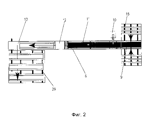
Figure 2 shows schematic representation of a process line for multi-layer
construction
elements.
Figure 3 shows the outer elements feeding unit and the thermal insulation
layer feeding unit.
Figure 4 shows a fragment of the outer elements feeding unit, the thermal
insulation layer
feeding unit, and a fragment of the pressing unit.
Figure 5 shows a fragment of the pressing unit, the sawing unit, and a
fragment of the removal
unit.
Figure 6 shows a fragment of the pressing unit, the sawing unit, and the
removal unit.
DETAILED DESCRIPTION OF THE PREFERRED EMBODIMENT
Multi-layer construction element (1) includes outer elements (2) and thermal
insulation layer (3)
placed between them made, for example, of polyurethane foam, polystyrene,
polystyrene foam,
urea formaldehyde foam, polycarbonate (polyurea). Due to the unique properties
of these
materials, thermal insulation layer (3) easily takes on the desired shape and
is an excellent thermal
and sound insulation. The materials used for the thermal insulation layer are
also resistant to
different weather conditions. The upper and lower surface (4) of the outer
elements (2) of the
multi-layer construction element (1) is made with longitudinal pans (5) along
the entire outer
element (2). The multi-layer construction element (1) additionally contains
longitudinal joints (6)
that are included in the pans (5) of the upper and lower surface (4) of outer
elements (2). The joint
(6) allows for easy formation of a construction structure of multi-layer
construction elements (1)
without additional fastening. Multi-layer construction element (1) is made
with the possibility of
both horizontal and vertical laying, which gives new opportunities in the
design and construction.
When gluing multi-layer construction elements (1) to each other, e.g. a two-
component
polyurethane adhesive is used, which allows for achievement of a continuous
thermal circuit,
6
CA 03059551 2019-10-09
English translation as originally filed
Docket No.: 1439-001
including in the corners of the structure. When the bottom layer of the
masonry is heated, warm
air rises freely over the entire height of the wall and evenly warms its
entire surface. Rectangular
pans (7) for the electrical wiring duct are made in the thermal insulation
layer (3). The outer
elements (2) can be made of glued beam, coreboard, plywood, bricks with a high
degree of
hollowness, or stone. Outer elements (2) of multi-layer construction element
(1) do not require
additional external finishing, which significantly reduces the facility
commissioning time and
reduces the cost of finishing works. The thermal insulation layer (3) can be
reinforced.
Reinforcement is performed, for example, with wooden, composite crosspieces,
gratings made of
metal, composite, basalt plastic fittings, composite, plastic gratings, metal
shavings, etc. (see Fig.
1).
Process line (8) for the production of multi-layer construction elements (1),
including the following
interconnected elements: outer elements feeding unit (9), thermal insulation
layer feeding unit
(10), pressing unit (11), sawing unit (12), and removal unit (13) for ready-
made multi-layer
construction elements (1) installed on frame (14). Frame (14) is made of
machine-tool aluminium,
which makes the construction easier and ensures high precision of assembly.
The outer elements
feeding unit (9) is equipped with a side feed conveyor (15) for outer elements
(2) made in the form
of a belt conveyor (16) with the possibility of vertical orientation of outer
elements (2) during the
installation on the conveyor. The side feed conveyor (15) is made in the form
of a sequence of belt
conveyors (16), with possibility of feeding of outer elements (2) of different
lengths and
overturning unit for outer elements (2) from horizontal to vertical position.
The outer elements
feeding unit (9) is equipped with two outer guides (17) and middle guide (18).
Outer guides (17)
limit the outer elements (2) from the outside, and the inner guide (18) fixes
the distance between
the outer elements (2), and determines the width of the thermal insulation
layer (3). The thermal
insulation layer feeding unit (10) is designed to allow for mixing of at least
two components and
supply of mixture between outer elements (2). For mixing and supply of thermal
insulation layer
(3), a dosing unit with a mixer is used. Thermal insulation layer (3) is fed
in liquid form, and its
foaming and solidification takes place in the pressing unit (11). The pressing
unit (11) is made in
the form of a two-level belt conveyor (19). The upper level of the two-level
conveyor belt (22) fits
tightly to the outer elements (2), thus limiting and forming the top layer of
thermal insulation (3).
The frame (14) in the area of the pressing unit (11) is equipped with stands
(20) fixing the distance
between the levels of two-level belt conveyor (19), where each of these stands
(20) is equipped
7
CA 03059551 2019-10-09
English translation as originally filed
Docket No.: 1439-001
with a height adjuster of outer elements (21) on the top. The upper level of
the two-level conveyor
(22) is shorter than the lower level (23) to provide a platform for the
thermal insulation layer (10)
on the lower level of the two-level conveyor (23), and the central part (24)
of both levels (22) and
(23) is equipped with special dense stickers (25) for the formation of the
upper and lower working
joints (7) of the thermal insulation layer. Special dense stickers (25) can be
made, for example, of
PVC. The two-level belt conveyor (19) of the pressing unit (11) is equipped
with paired thrust
roller blocks (26) that fix the outer dimensions of the multi-layer
construction element (1). Thrust
roller blocks (26) are located at the lower level (23) of the two-level
conveyor and at a certain
distance from each other, and the first pair of thrust roller blocks (27) is
located in an area of
thermal insulation layer feeding unit (10) for fixing outer elements (2) as
the exit feeding unit (9)
and transition to thermal insulation layer feeding unit (10). Sawing unit (12)
is made with the
possibility of reciprocating motion of saw (28) with the speed of the conveyor
belt movement.
Sawing unit (12) moves horizontally, in the same direction and with the belt
speed in pressing unit
(11); saw (28) makes a vertical movement from top to bottom for sawing multi-
layer construction
elements (1), then from bottom to top, returning the saw to its original
position; sawing unit (12)
goes back against the movement of the belt in pressing unit (11) and is ready
for the next cut.
Removal unit (13) for ready-made multi-layer construction elements (1) is made
in the form of a
roller conveyor (29) with a side unloader (30) for ready-made multi-layer
construction elements
(1). (See Fig. 2, 3, 4, 5, 6).
A method of production of multi-layer construction element (1), including
laying of outer elements
(2), filling the space between outer elements (2) with thermal insulation
layer (3), aging and
pressing of multi-layer construction element (1) and removal of finished multi-
layer construction
element (2) from the process line (8). The outer elements (2) are
provisionally prepared by forming
the upper and lower pan (5) of each outer element (2). The outer elements (2)
are then fed with
vertical orientation from two opposite sides. The outer elements (2) are then
fixed with guides (17)
and (18). When the outer elements (2) arrive at the insulation layer feeding
unit (10), the outer
elements (2) are fixed with thrust roller blocks (26). Then the space between
outer elements (2) is
filled with a thermal insulation layer (3), the components of which are pre-
mixed, and the thermal
insulation layer (3) itself is fed from above. Then outer elements (2) with a
thermal insulation layer
(3) are fed into the two-level conveyor (19) of the pressing unit (11), where
the level of the second
layer is fixed with stands (20), and the upper (22) and lower (23) levels of
the conveyor forms the
8
CA 03059551 2019-10-09
English translation as originally filed
Docket No.: 1439-001
upper and lower working joints of the thermal insulation layer (7). After
that, the outer elements
(2) with the thermal insulation layer (3) are pressed for 7-10 minutes at a
temperature of 20-65 C.
After that, the multi-layer construction element (1) is fed into the sawing
unit (12), where it is sawn
to the specified lengths. The ready-made multi-layer construction elements (1)
are fed into the
removal unit (13) and then removed from the line by a side unloader (30). (See
Fig. 2).
The following can be used for implementation of the proposed multi-layer
construction
element, a way of its production and a process line for the production of a
multi-layer construction
element:
¨the room featuring dimensions of no more than 50x18 meters,
¨ any low/high pressure filling machine with metering unit and mixer,
¨ air compressor.
The developers of the proposed multi-layer construction element, a way of
production
thereof and a process line for the production of a multi-layer construction
element have performed
tests of the multi-layer construction element that produced the following
results:
¨ compression strength: from 20kgf/cm2,
¨ bending strength: Ru32 over 25MPa,
¨ layer adhesive strength: from 0.226MPa,
¨ design heat transmission resistance: R over 10.
The advantages of the proposed method of corrosion processes control are the
following:
¨ low cost of the multi-layer construction element,
¨ possibility to use multi-layer construction element without additional
insulation, without
steam or wind protection films,
¨ high speed of building the structures made of multi-layer construction
element,
¨ possibility of vertical laying of multi-layer construction element during
building,
9
CA 03059551 2019-10-09
English translation as originally filed
Docket No.: 1439-001
¨ dense connection of outer elements due to self-adhesion,
¨ a variety of materials for outer elements,
¨ high performance of the process line,
¨ simplicity of process line equipment,
¨ simplicity of process line equipment maintenance,
¨ low power consumption of the process line,
¨ possibility to feed outer elements with vertical orientation,
¨ compactness of the process line placement,
¨ performance of the process line from 24,000 to 100,000m2 per year,
¨ use of outer elements with a thickness from 18 to 60mm and with a height
from 150 to
400mm.
The purpose, i.e. creation of a simple and convenient multi-layer construction
element to
combine in the structures that results in a minimum shrinkage with the
possibility of using a multi-
layer construction element for building bearing walls, internal partitions,
floors and ceilings, as
well as the production of ready-made walls with all the working holes by
gluing and fastening in
the production; a high-performance process line for multi-layer construction
elements using well-
known equipment with low energy consumption, as well as the possibility of
supplying outer
vertically oriented elements, and continuous and low-cost method of
manufacturing multi-layer
construction elements.
The data listed above confirm the industrial applicability of the proposed
multi-layer
construction element, the way of production thereof and the process line for
the production of the
multi-layer construction element.
List of positions:
1. multi-layer construction element,
2. outer element,
CA 03059551 2019-10-09
English translation as originally filed
Docket No.: 1439-001
3. thermal insulation layer,
4. upper and lower surface of outer elements,
5. rectangular pans,
6. rectangular joints,
7. working rectangular pans in the thermal insulation layer,
8. process line,
9. outer element feeding unit,
10. thermal insulation layer feeding unit,
11. pressing unit,
12. sawing unit,
13. removal unit,
14. frame,
15. side feed conveyor for outer elements,
16. belt conveyor,
17. outer guide,
18. middle guide,
19. two-level belt conveyor,
20. stands,
21. outer element height regulator,
22. upper level of the two-level conveyor,
23. lower level of the two-level conveyor,
24. central part of the two-level conveyor,
25. special dense sticker,
26. paired thrust roller blocks,
27. first pair of thrust roller blocks,
28. saw,
29. roller conveyor,
30. side unloader.
11