Note: Descriptions are shown in the official language in which they were submitted.
CA 03059557 2019-10-09
WO 2018/190943 PCT/US2018/017852
- 1 -
ELECTROSTATIC DISCHARGE MITIGATION FOR A FIRST SPACECRAFT
OPERATING IN PROXIMITY TO A SECOND SPACECRAFT AND RELATED
METHODS
PRIORITY CLAIM
This application claims the benefit of the filing date of United States
Provisional
Patent Application Serial Number 62/484,969, filed April 13, 2017, for
"Electrostatic
Discharge Mitigation for a First Spacecraft Operating in Proximity to a Second
Spacecraft," and United States Patent Application Serial No. 15/829,758, filed
December 1,
2017, for "Electrostatic Discharge Mitigation for a First Spacecraft Operating
in Proximity
to a Second Spacecraft," the disclosure of each of which is hereby
incorporated herein in its
entirety by this reference.
FIELD
The present disclosure relates systems and methods for addressing the
challenges
that arise with regard to electrostatic discharge when a first spacecraft is
operating in
proximity with a second spacecraft, and particularly when the first spacecraft
approaches
the second spacecraft to dock or otherwise contact the second spacecraft.
BACKGROUND
Thousands of spacecraft orbit the Earth for performing various functions
including, for
example, telecommunication, GPS navigation, weather forecasting, and mapping.
More
complex large spacecraft are also in orbit, including the International Space
Station, to which
nations throughout the world send crew and supplies for scientific
investigation and research.
However, spacecraft periodically require servicing to extend their functioning
life span.
Servicing may include, for example, component repair, refueling, orbit
raising, station-
keeping, momentum balancing, or other maintenance. Without life extension
maintenance,
these spacecraft may fall out of service, and replacement is generally
extraordinarily
expensive and can have a lead time of years. In the case of unmanned
spacecraft, to
accomplish such servicing, a servicing spacecraft may be sent into orbit to
dock with a client
spacecraft requiring maintenance, and subsequent to docking, perform life-
extending
maintenance on the client.
However, spacecraft or other bodies in orbit often possess different
electrical
potentials. When two spacecraft approach each other, a significant risk arises
that an
electrostatic discharge could occur between the two spacecraft. Spacecraft
contain numerous
CA 03059557 2019-10-09
WO 2018/190943 PCT/US2018/017852
- 2 -
electronic systems that could be damaged or destroyed by such an electrostatic
discharge
event. Various patents and publications have considered how to mitigate the
risk of an
electrostatic discharge event, including U.S. Patent Nos. 7,070,151,
7,216,833, 7,216,834,
7,461,818, 7,484,690, 7,575,199, 7,588,213, 7,611,096, 7,611,097, 7,624,950,
and 8,205,838,
the disclosure of each of which is hereby incorporated herein in its entirety
by this reference.
However, an improved system and method for mitigating electrostatic discharge
between a
first spacecraft and a second spacecraft is desirable.
DISCLOSURE
Methods and systems for mitigating the risk of an electrostatic discharge due
to static
charge differentials between a first spacecraft and a second spacecraft are
disclosed herein.
Various embodiments teach a passive electrostatic discharge mitigation device
facilitating the
safe reduction of static potential between the first and second spacecraft
prior to and/or upon
contact. Some embodiments provide an apparatus to direct the flow of a static
discharge
current in a manner that minimizes risk to the electronic components of the
first and second
spacecraft, which may be accomplished by providing one or more whiskers
electrically
connected to a passive electrostatic discharge mitigation device. Some
embodiments provide
for actively mitigating static potential between a first spacecraft and a
second spacecraft by
means of an electric propulsion system provided on the first spacecraft. Some
embodiments
provide for both actively and passively mitigating static potential between
the first spacecraft
and the second spacecraft.
Certain embodiments teach a system and method for mitigating electrostatic
discharge
between a first space vehicle and a second space vehicle comprising a passive
electrostatic
discharge mitigation system situated on the first space vehicle, wherein the
passive
electrostatic discharge mitigation system comprises one or more resistors and
wherein the
passive electrostatic discharge mitigation system comprises one or more
ferrite beads. In some
embodiments, the passive electrostatic discharge mitigation system reduces an
electrostatic
discharge current between the first space vehicle and the second space vehicle
to less than or
equal to about 800 milliamps over a time period of less than or equal to about
90 nanoseconds.
Some embodiments further comprise one or more whiskers as part of the passive
electrostatic
discharge mitigation system.
Certain embodiments teach a system and method for mitigating electrostatic
discharge
between a first space vehicle and a second space vehicle comprising an active
electrostatic
discharge system situated on the first space vehicle, wherein the active
electrostatic discharge
CA 03059557 2019-10-09
WO 2018/190943 PCT/US2018/017852
- 3 -
system manipulates a plasma field. In various embodiments, the manipulated
plasma field is
the plasma field of the first space vehicle, the plasma field of the second
space vehicle, or the
plasma fields of both the first and second space vehicles. The active
electrostatic discharge
system may manipulate the plasma field using an electric propulsion apparatus.
Some
embodiments provide that the electric propulsion apparatus produce a plasma
field significant
enough to reduce the potential between the first space vehicle and the second
space vehicle to
less than about +/- 200 volts. The electric propulsion apparatus may be one or
more Hall
Effect Thrusters.
Certain embodiments teach a system and method for mitigating electrostatic
discharge
.. between a first space vehicle and a second space vehicle, comprising a
propulsion mechanism
for maneuvering the first space vehicle in space; a capture mechanism
positioned on the first
space vehicle for at least temporarily joining the first space vehicle to the
second space
vehicle; and a mechanism for passively mitigating electrostatic discharge. The
mechanism for
passively mitigating electrostatic discharge may include one or more compliant
members,
which in some embodiments may be one or more whiskers. In some embodiments,
the
compliant member provides the first physical contact between the first space
vehicle and the
second space vehicle. The compliant member may contact an engine of the second
space
vehicle and, in some embodiments, the compliant member always contacts the
engine before
any other physical structure on the second space vehicle. The engine of the
second space
vehicle may be a liquid apogee engine. According to some embodiments, the
capture
mechanism includes a probe. The compliant member may be positioned on the
probe. Some
embodiments provide that the compliant member extends from the first space
vehicle in a
direction toward the second space vehicle. The compliant member may be highly
compliant.
In some embodiments, the compliance of the compliant member is provided in
part by a
torsion spring. According to some embodiments, the compliant member is
comprised of
beryllium copper.
Certain embodiments teach a system and method for mitigating electrostatic
discharge
between a first space vehicle and a second space vehicle comprising a passive
electrostatic
discharge mitigation system situated on the first space vehicle; and an active
electrostatic
discharge system situated on the first space vehicle. In some embodiments, the
passive
electrostatic discharge mitigation system comprises one or more resistors and
wherein the
passive electrostatic discharge mitigation system comprises one or more
ferrite beads. In some
embodiments, the active electrostatic discharge system manipulates a plasma
field. The
passive electrostatic discharge mitigation system may reduce an electrostatic
discharge current
CA 03059557 2019-10-09
WO 2018/190943 PCT/US2018/017852
- 4 -
between the first space vehicle and the second space vehicle to less than or
equal to about 800
milliamps over a time period of less than or equal to about 90 nanoseconds.
The system
further may include a whisker or a plurality of whiskers. The whisker may
provide the first
physical contact between the first space vehicle and the second space vehicle,
and may contact
an engine of the second space vehicle. The whisker may extend from the first
space vehicle in
a direction toward the second space vehicle. In some embodiments, the whisker
always
contacts the engine before any other physical structure on the second space
vehicle. The
capture mechanism may include a probe, and the whisker may be positioned on
the probe in
some embodiments. The whisker may be highly compliant and, in some
embodiments, the
compliance is provided in part by a torsion spring. In some embodiments, the
whisker is
comprised of beryllium copper. In some embodiments, the manipulated plasma
field is the
plasma field of the first space vehicle, the plasma field of the second space
vehicle, or the
plasma fields of both the first and second space vehicles. The active
electrostatic discharge
system may manipulate the plasma field using an electric propulsion apparatus,
which may be
one or more Hall Effect Thrusters in some embodiments. The electric propulsion
apparatus
may produce a plasma field significant enough to reduce the potential between
the first space
vehicle and the second space vehicle to less than about +1- 200 volts.
The above summary is not intended to describe each illustrated embodiment or
every
implementation of the present disclosure.
BRIEF DESCRIPTION OF THE DRAWINGS
The drawings included in the present application are incorporated into, and
form part
of, the specification. They illustrate embodiments of the present disclosure
and, along with the
description, serve to explain the principles of the disclosure. The drawings
are only illustrative
of certain embodiments and do not limit the disclosure.
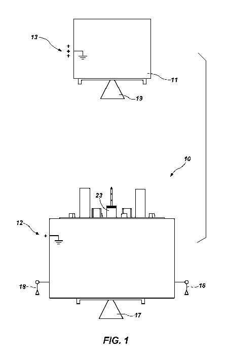
FIG. 1 is a side elevational view of a first spacecraft and a second
spacecraft in
proximity, according to one or more embodiments.
FIG. 2 is a perspective diagram of a passive electrostatic discharge
mitigation system,
according to one or more embodiments.
FIG. 3 is a diagram of a circuit of a passive electrostatic discharge
mitigation system,
according to one or more embodiments.
FIG. 4 is a perspective view of a housing for a passive electrostatic
discharge
mitigation system, according to one or more embodiments.
CA 03059557 2019-10-09
WO 2018/190943 PCT/US2018/017852
- 5 -
FIG. 5 is a perspective view of a housing for a passive electrostatic
discharge
mitigation system mounted on a capture apparatus, according to one or more
embodiments.
FIG. 6 is a perspective view of a first electrical contact apparatus,
according to one or
more embodiments.
FIG. 7 is a perspective view of a capture apparatus with a passive
electrostatic
discharge mitigation system mounted thereon approaching an engine of a second
spacecraft,
according to one or more embodiments.
FIG. 8 is a graphical representation of a sample anticipated static potential
difference
between portions of a first spacecraft and a second spacecraft, according to
one or more
embodiments.
FIGS. 9A and 9B are graphical representations of the operation of an active
electrostatic discharge mitigation system to create plasma, according to one
or more
embodiments.
Although embodiments of the disclosure disclosed herein are amenable to
various
modifications and alternative forms, specifics thereof have been shown by way
of example in
the drawings and will be described in detail. It should be understood,
however, that the
intention is not to limit the disclosure to the particular embodiments
described. On the
contrary, the intention is to cover all modifications, equivalents, and
alternatives falling within
the scope of the disclosure.
MODE(S) FOR CARRYING OUT THE INVENTION
As used herein, the term "substantially" in reference to a given parameter
means and
includes to a degree that one skilled in the art would understand that the
given parameter,
property, or condition is met with a small degree of variance, such as within
acceptable
manufacturing tolerances. For example, a parameter that is substantially met
may be at least
about 90% met, at least about 95% met, or even at least about 99% met.
The inventors have recognized the risk of damage from electrostatic discharges
due to
static charge differentials associated with an approach of a first spacecraft
to a second
spacecraft. In some embodiments, the first spacecraft may comprise a capture
assembly that
beneficially provides electrostatic mitigation to protect electronic
components in the first
spacecraft, the second spacecraft, or both. Some embodiments provide systems
and methods
for reducing the static potential between a first and second spacecraft in a
manner that protects
the components of both spacecraft.
CA 03059557 2019-10-09
WO 2018/190943 PCT/US2018/017852
- 6 -
FIG. 1 is a side elevation view of two spacecraft in proximity in space
according to
one embodiment. In some embodiments, first spacecraft 10 may be designed to
dock to
second spacecraft 11. First spacecraft 10 may be a servicer spacecraft
designed to provide
service to second spacecraft 11. According to some embodiments, second
spacecraft 11 may
be a satellite in orbit around a body such as the Earth. If second spacecraft
11 is in orbit
around Earth, second spacecraft 11 may be in low or medium Earth orbit,
geosynchronous or
above-geosynchronous orbit, or any other orbit.
First spacecraft 10 may have a capture apparatus 23 with a probe and a
propulsion
system. The propulsion system of first spacecraft 10 may include one or more
main
thrusters 17, one or more gimbaled thrusters 18, or both. Main thruster 17,
gimbaled
thrusters 18, or both may be electric propulsion apparatuses. Second
spacecraft 11 may have
an engine 19. Engine 19 can be any type of suitable engine or motor for a
spacecraft,
including a liquid apogee engine or a solid fuel motor. First spacecraft 10
may have a first
static potential 12, and second spacecraft 11 may have a second static
potential 13. Upon
approach or contact of first spacecraft 10 to second spacecraft 11, a
differential between first
static potential 12 and second static potential 13 may cause an electrostatic
discharge. Such an
electrostatic discharge may cause damage to first spacecraft 10, second
spacecraft 11, or both,
unless the differential between first static potential 12 and second static
potential 13 is
mitigated.
FIG. 2 is a perspective diagram of a passive electrostatic discharge
mitigation
system 20 according to one embodiment. A circuit 32, as show in FIG. 3, of
passive
electrostatic discharge mitigation system 20 may be housed within a housing or
box 24.
Passive electrostatic discharge system 20 may be electrically connected to
capture apparatus
23 or another portion of first spacecraft 10. Passive electrostatic discharge
system 20 may also
be electrically connected to a first electrical contact apparatus 25. First
electrical contact
apparatus 25 may include one or more compliant members (e.g., whiskers 26).
Whiskers 26
comprise an electrically conductive material. Whiskers 26 may be comprised at
least in part of
beryllium copper.
FIG. 3 is a diagram of a circuit 32 of a passive electrostatic discharge
mitigation
system 20 according to one embodiment. Passive electrostatic discharge
mitigation system 20
may be configured as a resistance inductance, or RL, circuit comprising one or
more resistive
elements 27 and one or more inductive elements 28. In some embodiments, the
one or more
inductive elements 28 may be an inductor, or one or more ferrite beads, one or
more chokes,
or another inductive element. The one or more resistive elements 27 may be one
or more
CA 03059557 2019-10-09
WO 2018/190943 PCT/US2018/017852
- 7 -
resistors and, in some embodiments, may be configured to provide a resistance
of more than
1 megaohm and, in some embodiments, may be configured to provide a resistance
of greater
than or equal to 15 megaohms. When first spacecraft 10 and second spacecraft
11 make
contact or come in close enough proximity for a static electric arc to occur
between the first
spacecraft 10 and second spacecraft 11, the passive electrostatic discharge
mitigation
system 20 provides an equalization path for the voltage differential between
the two spacecraft
and allows the different static charges to equalize.
As a result of the passive electrostatic discharge mitigation system 20,
static voltage
differential between the two spacecraft 10, 11 may be converted into heat to
remove energy.
This dissipation will reduce, or in some instances eliminate, electrostatic
discharges and the
amplitude and rise time of any associated voltage spikes that may be
detrimental to either
spacecraft. In some embodiments, the voltage differential may be discharged
over a period of
time, for example 50-90 nanoseconds or more. In some embodiments, discharge
current may
be reduced below 800 milliamps by passive electrostatic discharge mitigation
system 20.
According to certain embodiments, the one or more inductive elements 28 and
one or more
resistive elements 27 may be selected to accommodate a transient static
potential difference
between first spacecraft 10 and second spacecraft 11 of up to or more than 10
kilovolts. In
some embodiments, the passive electrostatic discharge mitigation system 20 may
be
configured to have parallel circuit paths that may mitigate the risk of
individual component
failures.
FIG. 4 is a perspective view of a housing 24 for a passive electrostatic
discharge
mitigation system 20 (FIG. 2). Insulated conductor 21 provides electrical
connection between
the passive electrostatic discharge mitigation system 20 and at least one
first electrical contact
apparatus 25 (FIG. 2), wherein first electrical contact apparatus 25 may
comprise a compliant
member which may be in the form of whisker 26 (FIG. 2). Insulated grounding
conductor 22
provides electrical connection between the passive electrostatic discharge
mitigation system
20 and capture apparatus 23 or elsewhere on a body of first spacecraft 10
(FIG. 1).
FIG. 5 is a perspective view of a housing 24 for a passive electrostatic
discharge
mitigation system 20 (FIG. 2) mounted to capture apparatus 23. Insulated
conductor 21
provides electrical connection between the passive electrostatic discharge
mitigation system
20 and at least one first electrical contact apparatus 25, wherein first
electrical contact
apparatus 25 may comprise a compliant member such as whisker 26.
FIG. 6 is a perspective view of first electrical contact apparatus 25. First
electrical
contact apparatus 25 may include one or more compliant members such as
whiskers 26.
CA 03059557 2019-10-09
WO 2018/190943 PCT/US2018/017852
- 8 -
Whiskers 26 may comprise a spring element 29 that may increase compliance of
whiskers 26.
Spring element 29 may be a torsion spring. Spring element 29 may allow
whiskers 26 to move
in a substantially rotational manner when whiskers 26 contact engine 19 (FIG.
2) or another
physical structure on the second spacecraft 11 (FIG. 1). First electrical
contact apparatus 25
may be designed to be electrically isolated from capture apparatus 23, for
example, by one or
more insulated posts 30 that electrically isolate the conductive components,
such as the
whiskers 26, from the capture apparatus 23. Insulated posts 30 may be
comprised of a
machinable glass ceramic or other insulating material sufficient to
electrically isolate the
conductive components. In some embodiments, the conductive components of first
electrical
contact apparatus 25 may be positioned 0.25 inch (0.635 cm) or more from the
closest
conductive component of capture apparatus 23, or another suitable distance to
prevent charge
creep or arcing.
FIG. 7 is a perspective view of a capture apparatus 23 with a passive
electrostatic
discharge mitigation system 20 mounted thereon approaching the engine 19 of
the second
spacecraft 11. Whiskers 26 may be designed to be of a sufficient length to
ensure that at least
one whisker 26 provides the first point of physical contact between first
spacecraft 10 and
second spacecraft 11. Whiskers 26 may be designed to be of a sufficient length
to ensure that
at least one whisker 26 is the only physical structure on the first spacecraft
10 to come within
a distance that would allow a static electric arc between first spacecraft 10
and second
spacecraft 11 before any portion of first spacecraft 10 physically contacts
second
spacecraft 11. In some embodiments, whiskers 26 may be at least 6 inches
(15.24 cm) in
length.
FIG. 8 depicts charge potential differentials of a first spacecraft in
relation to a second
spacecraft for use with an active electrostatic discharge mitigation system,
according to one
embodiment. FIG. 8 graphically represents sample anticipated static potential,
or charge,
differences between various portions of first spacecraft 10 and second
spacecraft 11. In some
embodiments, static potential differences may be on the order of 10 kilovolts
or more and
capacitance between the vehicles may be on the order of 100 picofarads or
more.
FIGS. 9A and 9B depict an active electrostatic discharge mitigation system 31
using
plasma. In some embodiments, the active electrostatic discharge mitigation
system 31 may
create a plasma field that can engulf both the first spacecraft 10 and the
second spacecraft 11.
In some embodiments, the active electrostatic discharge mitigation system 31
creates the
plasma field using one or more electric propulsion engines of first spacecraft
10, which may
be main thruster 17, one or more gimbaled thrusters 18, both, or another
engine. The one or
CA 03059557 2019-10-09
WO 2018/190943 PCT/US2018/017852
- 9 -
more electric propulsion engines may be Hall Effect Thrusters. The plasma
field created by
the active electrostatic discharge mitigation system 31 may be low temperature
plasma. Active
electrostatic discharge mitigation system 31 can be operated to reduce the
static potential
measured to ground reference of each of first spacecraft 10 and second
spacecraft 11. The
reduction of static potential differential between first spacecraft 10 and
second spacecraft 11
may be to a level less than about 5 kilovolts, less than about 1 kilovolt,
less than about 200
volts, or less than about 100 volts in various embodiments. In addition, use
of the active
electrostatic discharge mitigation system 31 may reduce potential ground
bounce between the
first spacecraft 10 and second spacecraft 11.
In some embodiments, the first spacecraft 10 may have both a passive
electrostatic
discharge mitigation system 20 and an active electrostatic discharge
mitigation system 31. In
such embodiments, active electrostatic discharge mitigation system 31 may
reduce differential
static potential between first spacecraft 10 and second spacecraft 11 before
contact, and
passive electrostatic discharge mitigation system 20 to mitigate remaining
differential static
potential between first spacecraft 10 and second spacecraft 11 upon contact or
approach
sufficient to permit electrostatic arcing. In such embodiments, passive
electrostatic discharge
mitigation system 20 and active electrostatic discharge mitigation system 31
provide
redundancy upon component failure of either system.
Further example embodiments are disclosed below.
Embodiment 1: A system for mitigating electrostatic discharge between a first
space
vehicle and a second space vehicle comprising a passive electrostatic
discharge mitigation
system situated on the first space vehicle, wherein the passive electrostatic
discharge
mitigation system comprises one or more resistors.
Embodiment 2: The system of Embodiment 1, wherein the passive electrostatic
discharge mitigation system reduces an electrostatic discharge current between
the first space
vehicle and the second space vehicle to less than or equal to about 800
milliamps over a time
period of less than or equal to about 90 nanoseconds.
Embodiment 3: The system of Embodiment 1, wherein the passive electrostatic
discharge mitigation system further comprises one or more inductive elements
selected from
the group comprising inductors, ferrite beads, and chokes.
Embodiment 4: The system of Embodiment 1, wherein the system further includes
one or more whiskers.
Embodiment 5: A system for mitigating electrostatic discharge between a first
space
vehicle and a second space vehicle comprising an active electrostatic
discharge system
CA 03059557 2019-10-09
WO 2018/190943 PCT/US2018/017852
- 10 -
situated on the first space vehicle, wherein the active electrostatic
discharge system
manipulates a plasma field.
Embodiment 6: The system of Embodiment 5, wherein the plasma field is the
plasma
field of the first space vehicle.
Embodiment 7: The system of Embodiment 5, wherein the plasma field is the
plasma
field of the second space vehicle.
Embodiment 8: The system of Embodiment 5, wherein the active electrostatic
discharge system manipulates the plasma field using an electric propulsion
apparatus.
Embodiment 9: The system of Embodiment 8, wherein the electric propulsion
apparatus produces a plasma field significant enough to reduce the potential
between the first
space vehicle and the second space vehicle to less than about +1- 200 volts.
Embodiment 10: The system of Embodiment 8, wherein the electric propulsion
apparatus is one or more Hall Effect Thrusters.
Embodiment 11: A system for mitigating electrostatic discharge between a first
space
vehicle and a second space vehicle, comprising: a propulsion mechanism for
maneuvering the
first space vehicle in space; a capture mechanism positioned on the first
space vehicle for at
least temporarily joining the first space vehicle to the second space vehicle;
and a mechanism
for passively mitigating electrostatic discharge when the first space vehicle
and the second
space vehicle are joining.
Embodiment 12: The system of Embodiment 11, wherein the mechanism for
passively
mitigating electrostatic discharge includes one or more whiskers.
Embodiment 13: The system of Embodiment 12, wherein the whisker provides the
first physical contact between the first space vehicle and the second space
vehicle.
Embodiment 14: The system of Embodiment 13, wherein the whisker is configured
to
contact an engine of the second space vehicle when the first space vehicle and
the second
space vehicle are joining.
Embodiment 15: The system of Embodiment 14, wherein the whisker is positioned
to
contact the engine before any other physical structure on the second space
vehicle when the
first space vehicle and the second space vehicle are joining.
Embodiment 16: The system of Embodiment 15, wherein the engine is a liquid
apogee
engine.
Embodiment 17: The system of Embodiment 12, wherein the capture mechanism
includes a probe.
CA 03059557 2019-10-09
WO 2018/190943 PCT/US2018/017852
- 11 -
Embodiment 18: The system of Embodiment 17, wherein the whisker is positioned
on
the probe.
Embodiment 19: The system of Embodiment 13, wherein there are a plurality of
whiskers.
Embodiment 20: The system of Embodiment 13, wherein the whisker extends from
the first space vehicle in a direction toward a location where the second
space vehicle is
positioned when the first space vehicle and the second space vehicle are
joining.
Embodiment 21: The system of Embodiment 13, wherein the whisker is configured
to
be highly compliant.
Embodiment 22: The system of Embodiment 21, wherein the compliance is provided
in part by a torsion spring.
Embodiment 23: The system of Embodiment 13, wherein the whisker is comprised
of
beryllium copper.
Embodiment 24: A method for mitigating electrostatic discharge between a first
space
vehicle and a second space vehicle comprising: providing a passive
electrostatic discharge
mitigation system on the first space vehicle, wherein the passive
electrostatic discharge
mitigation system comprises one or more resistors; and configuring the first
contact between
the first space vehicle and the second space vehicle to ensure that any
electrostatic discharge
between the first space vehicle and the second space vehicle is directed
through the passive
electrostatic discharge mitigation system.
Embodiment 25: The method of Embodiment 24, wherein the method further
comprises reducing an electrostatic discharge current between the first space
vehicle and the
second space vehicle to less than or equal to about 800 milliamps over a time
period of less
than or equal to about 90 nanoseconds using the passive electrostatic
discharge mitigation
system.
Embodiment 26: The method of Embodiment 24, wherein the passive electrostatic
discharge mitigation system further comprises one or more inductive elements
selected from
the group comprising inductors, ferrite beads, and chokes.
Embodiment 27: The method of Embodiment 24, wherein the passive electrostatic
.. discharge mitigation system further includes one or more whiskers.
Embodiment 28: A method for mitigating electrostatic discharge between a first
space
vehicle and a second space vehicle comprising: providing an active
electrostatic discharge
system situated on the first space vehicle; and manipulating a plasma field
using the active
electrostatic discharge system.
CA 03059557 2019-10-09
WO 2018/190943 PCT/US2018/017852
- 12 -
Embodiment 29: The method of Embodiment 28, wherein the manipulating of the
plasma field comprises manipulating the plasma field of the first space
vehicle.
Embodiment 30: The method of Embodiment 28, wherein the manipulating of the
plasma field comprises manipulating the plasma field of the second space
vehicle.
Embodiment 31: The method of Embodiment 28, wherein the manipulating of the
plasma field comprises manipulating the plasma field using an electric
propulsion apparatus.
Embodiment 32: The method of Embodiment 31, wherein the method further
comprises producing a plasma field significant enough to reduce the potential
between the
first space vehicle and the second space vehicle to less than about +/- 200
volts using the
electric propulsion apparatus.
Embodiment 33: The method of Embodiment 31, wherein the electric propulsion
apparatus is one or more Hall Effect Thrusters.
Embodiment 34: A method for mitigating electrostatic discharge between a first
space
vehicle and a second space vehicle, comprising: providing a capture mechanism
positioned on
the first space vehicle for at least temporarily joining the first space
vehicle to the second
space vehicle; maneuvering the first space vehicle in space in proximity to
the second space
vehicle; and providing a mechanism for passively mitigating electrostatic
discharge between
the first space vehicle and the second space vehicle.
Embodiment 35: The method of Embodiment 34, wherein the mechanism for
passively mitigating electrostatic discharge includes a whisker.
Embodiment 36: The method of Embodiment 35, wherein the method further
includes
physically contacting the first space vehicle and the second space vehicle,
wherein the whisker
provides the first physical contact between the first space vehicle and the
second space vehicle
when the first space vehicle and the second space vehicle are joining.
Embodiment 37: The method of Embodiment 36, wherein the whisker is configured
to
contact an engine of the second space vehicle when the first space vehicle and
the second
space vehicle are joining.
Embodiment 38: The method of Embodiment 37, wherein the whisker is configured
to
contact the engine before any other physical structure on the second space
vehicle when the
first space vehicle and the second space vehicle are joining.
Embodiment 39: The method of Embodiment 38, wherein the engine is a liquid
apogee engine.
Embodiment 40: The method of Embodiment 35, wherein the capture mechanism
includes a probe.
CA 03059557 2019-10-09
WO 2018/190943 PCT/US2018/017852
- 13 -
Embodiment 41: The method of Embodiment 40, wherein the whisker is positioned
on
the probe.
Embodiment 42: The method of Embodiment 36, wherein there are a plurality of
whiskers.
Embodiment 43: The method of Embodiment 36, wherein the whisker extends from
the first space vehicle in a direction toward a location where the second
space vehicle is
positioned when the first space vehicle and the second space vehicle are
joining.
Embodiment 44: The method of Embodiment 36, wherein the whisker is highly
compliant.
Embodiment 45: The method of Embodiment 44, wherein the compliance is provided
in part by a torsion spring.
Embodiment 46: The method of Embodiment 36, wherein the whisker is comprised
of
beryllium copper.
Embodiment 47: A system for mitigating electrostatic discharge between a first
space
vehicle and a second space vehicle comprising: a passive electrostatic
discharge mitigation
system situated on the first space vehicle, wherein the passive electrostatic
discharge
mitigation system comprises one or more resistors; and an active electrostatic
discharge
system situated on the first space vehicle, wherein the active electrostatic
discharge system
manipulates a plasma field.
Embodiment 48: The system of Embodiment 47, wherein the passive electrostatic
discharge mitigation system reduces an electrostatic discharge current between
the first space
vehicle and the second space vehicle to less than or equal to about 800
milliamps over a time
period of less than or equal to about 90 nanoseconds.
Embodiment 49: The system of Embodiment 47, wherein the passive electrostatic
discharge mitigation system further comprises one or more inductive elements
selected from
the group comprising inductors, ferrite beads, and chokes.
Embodiment 50: The system of Embodiment 47, wherein the system further
includes
one or more whiskers.
Embodiment 51: The system of Embodiment 47, wherein the plasma field is the
plasma field of the first space vehicle.
Embodiment 52: The system of Embodiment 47, wherein the plasma field is the
plasma field of the second space vehicle.
Embodiment 53: The system of Embodiment 47, wherein the active electrostatic
discharge system manipulates the plasma field using an electric propulsion
apparatus.
CA 03059557 2019-10-09
WO 2018/190943 PCT/US2018/017852
- 14 -
Embodiment 54: The system of Embodiment 53, wherein the electric propulsion
apparatus produces a plasma field significant enough to reduce the potential
between the first
space vehicle and the second space vehicle to less than about +1- 200 volts.
Embodiment 55: The system of Embodiment 53, wherein the electric propulsion
apparatus is one or more Hall Effect Thrusters.
Embodiment 56: The system of Embodiment 49, wherein the whisker a configured
to
provide the first physical contact between the first space vehicle and the
second space vehicle.
Embodiment 57: The system of Embodiment 56, wherein the whisker is configured
to
contact an engine of the second space vehicle.
Embodiment 58: The system of Embodiment 57, wherein the whisker is configured
to
contact the engine before any other physical structure on the second space
vehicle.
Embodiment 59: The system of Embodiment 49, wherein a capture mechanism
includes a probe.
Embodiment 60: The system of Embodiment 59, wherein the whisker is positioned
on
the probe.
Embodiment 61: The system of Embodiment 60, wherein there are a plurality of
whiskers.
Embodiment 62: The system of Embodiment 60, wherein the whisker extends from
the first space vehicle in a direction toward a location where the second
space vehicle is
positioned when the first space vehicle and the second space vehicle are
joining.
Embodiment 63: The system of Embodiment 60, wherein the whisker is highly
compliant.
Embodiment 64: The system of Embodiment 63, wherein the compliance is provided
in part by a torsion spring.
Embodiment 65: The system of Embodiment 60, wherein the whisker is comprised
of
beryllium copper.
Embodiment 66: A method for mitigating electrostatic discharge between a first
space
vehicle and a second space vehicle comprising: providing an active
electrostatic discharge
system situated on the first space vehicle; manipulating a plasma field using
the active
electrostatic discharge system; providing a passive electrostatic discharge
mitigation system
on the first space vehicle, wherein the passive electrostatic discharge
mitigation system
comprises one or more resistors; and configuring the first contact between the
first space
vehicle and the second space vehicle to ensure that any electrostatic
discharge between the
CA 03059557 2019-10-09
WO 2018/190943 PCT/US2018/017852
- 15 -
first space vehicle and the second space vehicle is directed through the
passive electrostatic
discharge mitigation system.
Embodiment 67: The method of Embodiment 66, wherein the method further
comprises reducing an electrostatic discharge current between the first space
vehicle and the
second space vehicle to less than or equal to about 800 milliamps over a time
period of less
than or equal to about 90 nanoseconds using the passive electrostatic
discharge mitigation
system.
Embodiment 68: The method of Embodiment 66, wherein the passive electrostatic
discharge mitigation system further comprises one or more inductive elements
selected from
the group comprising inductors, ferrite beads, and chokes.
Embodiment 69: The method of Embodiment 66, wherein the passive electrostatic
discharge mitigation system further includes one or more whiskers.
Embodiment 70: The method of Embodiment 66, wherein the manipulating of the
plasma field comprises manipulating the plasma field of the first space
vehicle.
Embodiment 71: The method of Embodiment 66, wherein the manipulating of the
plasma field comprises manipulating the plasma field of the second space
vehicle.
Embodiment 72: The method of Embodiment 66, wherein the manipulating of the
plasma field comprises manipulating the plasma field using an electric
propulsion apparatus.
Embodiment 73: The method of Embodiment 72, wherein the method further
comprises producing a plasma field significant enough to reduce the potential
between the
first space vehicle and the second space vehicle to less than about +/- 200
volts using the
electric propulsion apparatus.
Embodiment 74: The method of Embodiment 72, wherein the electric propulsion
apparatus is one or more Hall Effect Thrusters.
Embodiment 75: The method of Embodiment 69, wherein the method further
includes
physically contacting the first space vehicle and the second space vehicle,
wherein the whisker
provides the first physical contact between the first space vehicle and the
second space vehicle
when the first space vehicle and the second space vehicle are joining.
Embodiment 76: The method of Embodiment 75, wherein the whisker is configured
to
contact an engine of the second space vehicle.
Embodiment 77: The method of Embodiment 76, wherein the whisker is configured
to
contact the engine before any other physical structure on the second space
vehicle.
Embodiment 78: The method of Embodiment 76, wherein the engine is a liquid
apogee engine.
CA 03059557 2019-10-09
WO 2018/190943 PCT/US2018/017852
- 16 -
Embodiment 79: The method of Embodiment 68, wherein a capture mechanism
includes a probe.
Embodiment 80: The method of Embodiment 79, wherein the whisker is positioned
on
the probe.
Embodiment 81: The method of Embodiment 80, wherein the whisker extends from
the first space vehicle in a direction toward a location where the second
space vehicle is
positioned when the first space vehicle and the second space vehicle are
joining.
Embodiment 82: The method of Embodiment 69, wherein the whisker is highly
compliant.
Embodiment 83: The method of Embodiment 82, wherein the compliance is provided
in part by a torsion spring.
Embodiment 84: The method of Embodiment 68, wherein the whisker is comprised
of
beryllium copper.
The embodiments of the disclosure described above and illustrated in the
accompanying drawings do not limit the scope of the disclosure, which is
encompassed by
the scope of the appended claims and their legal equivalents. Any equivalent
embodiments
are within the scope of this disclosure. Indeed, various modifications of the
disclosure, in
addition to those shown and described herein, such as alternative useful
combinations of
the elements described, will become apparent to those skilled in the art from
the
description. Such modifications and embodiments also fall within the scope of
the
appended claims and equivalents. The terminology used herein was chosen to
explain the
principles of the embodiments, the practical application or technical
improvement over
technologies found in the marketplace, or to enable others of ordinary skill
in the art to
understand the embodiments disclosed herein.