Note: Descriptions are shown in the official language in which they were submitted.
CA 03059566 2019-10-09
WO 2018/191236 PCT/US2018/026845
NEGATIVE PRESSURE MATTRESS SYSTEM
TECHNICAL FIELD
[0001] The present disclosure generally relates to systems
configured to
create negative pressure to draw ambient air away from a sleeping surface of a
mattress.
Methods of use are included.
BACKGROUND
[0002] Sleep is critical for people to feel and perform their best,
in every
aspect of their lives. Sleep is an essential path to better health and
reaching
personal goals. Indeed, sleep affects everything from the ability to commit
new
information to memory to weight gain. It is therefore essential for people to
use
bedding that suit both their personal sleep preference and body type in order
to
achieve comfortable, restful sleep.
[0003] Mattresses are an important aspect in achieving proper
sleep. It
is therefore beneficial to provide a mattress capable of maintaining a
preselected
temperature based on a user's sleep preference, so that the user achieves
maximum
comfort during sleep. However, conventional mattresses fail to create negative
pressure to draw ambient air away from a sleeping surface of the mattress.
This
disclosure describes an improvement over these prior art technologies.
SUMMARY
[0004] In one embodiment, in accordance with the principles of the
present
disclosure, a bedding system is provided that includes a box layer comprising
at least one
duct and at least one inlet. The at least one duct has a passageway that is in
communication with the at least one inlet. A capacitor layer is positioned
above the box
layer and includes a cavity that is in communication with the passageway. A
mattress layer
is positioned above the capacitor layer and includes a bottom surface and an
opposite top
surface that defines a sleep surface. The mattress layer comprises at least
one hole that
CA 03059566 2019-10-09
WO 2018/191236 PCT/US2018/026845
extends through the top and bottom surfaces and is in communication with the
cavity. A
central vacuum system comprises a power unit, at least one pipe having a first
end that is
connected to the power unit and a second end connected to an outlet and a hose
having a
first end that is connected to the outlet and a second end that is connected
to the at least
one inlet. In some embodiments, the power unit is configured to create a
vacuum that
draws air from the sleep surface and moves the air through the at least one
hole and into
the cavity such that the air moves through the at least one duct and into the
hose through
the at least one inlet.
BRIEF DESCRIPTION OF THE DRAWINGS
[0005] The present disclosure will become more readily apparent
from the
specific description accompanied by the following drawings, in which:
[0006] FIG. 1 is a perspective view of one embodiment of a bedding
system
in accordance with the principles of the present disclosure;
[0007] FIG. 2 is a side view of components of the system as shown
in FIG. 1;
[0008] FIG. 3 is a cross-sectional view of components of the system
shown
in FIG. 1 taken along lines A-A in FIG. 2;
[0009] FIG. 4 is a perspective view of components of the system
shown in
FIG. 1;
[0010] FIG. 5 is a perspective view, in part phantom, of components
of the
system shown in FIG. 1;
[0011] FIG. 6 is a perspective view of components of the system
shown in
FIG. 1;
[0012] FIG. 7 is a side view of components of the system as shown
in FIG. 1;
[0013] FIG. 8 is a cross-sectional view of components of the system
shown
in FIG. 1 taken along lines D-D in FIG. 7;
[0014] FIG. 9 is a cross-sectional view of components of the system
shown
in FIG. 1 taken along cross-sectional lines E-E in FIG. 7;
2
CA 03059566 2019-10-09
WO 2018/191236 PCT/US2018/026845
[0015] FIG. 10 is a top, detailed view of components of the system
shown in
FIG. 1;
[0016] FIG. 11 is a cross-sectional view of components of the
system shown
in FIG. 1 taken along lines B-B in FIG. 13;
[0017] FIG. 12 is a cross-sectional view of components of the
system shown
in FIG. 1 taken along lines C-C in FIG. 11;
[0018] FIG. 13 is a top view of components of the system shown in
FIG. 1;
[0019] FIG. 14 is a perspective view of components of the system
shown in
FIG. 1;
[0020] FIG. 15 is a perspective view of components of the system
shown in
FIG. 1;
[0021] FIG. 16 is a cross sectional view of components of the
system shown
in FIG. 1; and
[0022] FIG. 17 is a cross sectional view of components of the
system shown
in FIG. 1.
[0023] Like reference numerals indicate similar parts throughout
the
figures.
DETAILED DESCRIPTION
[0024] The exemplary embodiments of a bedding system and methods of
use are discussed in terms of a bedding system that creates negative pressure
to draw air
away from a sleep surface of a mattress to regulate the temperature of the
sleep surface.
The present disclosure may be understood more readily by reference to the
following
detailed description of the disclosure taken in connection with the
accompanying
drawing figures, which form a part of this disclosure. It is to be understood
that this
disclosure is not limited to the specific devices, methods, conditions or
parameters
described and/or shown herein, and that the terminology used herein is for the
purpose of describing particular embodiments by way of example only and is not
intended to be limiting of the claimed disclosure.
3
CA 03059566 2019-10-09
WO 2018/191236 PCT/US2018/026845
[00251 Also, as used in the specification and including the
appended
claims, the singular forms "a," "an," and "the- include the plural, and
reference to a
particular numerical value includes at least that particular value, unless the
context
clearly dictates otherwise. Ranges may be expressed herein as from "about" or
"approximately" one particular value and/or to "about" or "approximately"
another
particular value. When such a range is expressed, another embodiment includes
from the one particular value and/or to the other particular value. Similarly,
when
values are expressed as approximations, by use of the antecedent "about," it
will be
understood that the particular value forms another embodiment. It is also
understood
that all spatial references, such as, for example, horizontal, vertical, top,
upper, lower,
bottom, left and right, are for illustrative purposes only and can be varied
within the
scope of the disclosure. For example, the references "upper" and "lower" are
relative
and used only in the context to the other, and are not necessarily "superior"
and
"inferior".
[00261 The following discussion includes a description of an
ambient bed
having a heat reclaim system, related components and methods of using the
ambient
bed system in accordance with the principles of the present disclosure.
Alternate
embodiments are also disclosed. Reference will now be made in detail to the
exemplary embodiments of the present disclosure, which are illustrated in the
accompanying figures. Turning to FIGS. 1-15, there are illustrated components
of a
bedding system 20.
[0027] The components of bedding system 20 can be fabricated from
materials including metals, polymers and/or composites, depending on the
particular
application. For example, the components of bedding system 20, individually or
collectively, can be fabricated from materials such as fabrics or textiles,
paper or
cardboard, cellulosic-based materials, biodegradable materials, plastics and
other
polymers, metals, semi-rigid and rigid materials. Various components of
bedding
system 20 may have material composites, including the above materials, to
achieve
various desired characteristics such as strength, rigidity, elasticity,
performance and
durability. The components of bedding system 20, individually or collectively,
may
also be fabricated from a heterogeneous material such as a combination of two
or
4
CA 03059566 2019-10-09
WO 2018/191236 PCT/US2018/026845
more of the above-described materials. The components of bedding system 20 can
be extruded, molded, injection molded, cast, pressed and/or machined. The
components of bedding system 20 may be monolithically formed, integrally
connected or include fastening elements and/or instruments, as described
herein.
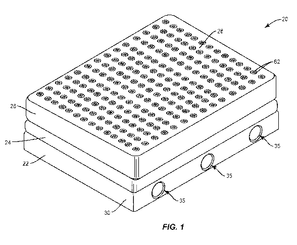
[0028] In one embodiment, shown in FIGS. 1-17, bedding system 20
includes a box layer 22, a capacitor layer 24 positioned above box layer 24
and a mattress
layer 26 positioned above capacitor layer 24. Mattress layer 26 includes a
sleep surface 28.
lithe temperature adjacent to sleep surface 28 deviates from a temperature
selected by a
user, bedding system 20 will create negative pressure that draws air away from
sleep
surface 28, as discussed herein.
[0029] As shown in FIGS, 1-4, box layer 22 comprises a housing 30
configured to support, enclose and/or protect other components of box layer
22, such
as, for example, one or a plurality of ducts 34. It is envisioned that box
layer 22
and/or housing 30 can have any size or shape, depending upon the requirements
of
a particular application. For example, box layer 22 and/or housing 30 can be
sized to
substantially conform to the size and shape of a particular mattress, such as,
for
example, a twin mattress, a queen mattress, a king mattress, etc. Ducts 34
each
define a passageway 32. Passageways 32 are each in communication with an
opening, such as, for example, an inlet 35 that extends through a wall of
housing 30.
[0030] It is envisioned that housing 30 may include any number of
ducts
34, such as, for example, one duct 34, two ducts 34, three ducts 34, four
ducts 34,
five ducts 34, six ducts 34, seven ducts 34, eight ducts 34, nine ducts 34,
ten ducts
34, etc. In one embodiment, a first sidewall of housing 30 includes three
inlets 35
that are spaced apart from one another and an opposite second sidewall of
housing
30 includes three inlets 35 that are spaced apart from one another. Each of
inlets 35
in the first sidewall is coaxial with one of inlets 35 in the second sidewall.
It is
envisioned that the first sidewall of housing 30 and the second sidewall of
housing 30
may each include one or a plurality of inlets 35. In some embodiments, at
least one
of the end walls of housing 30 that extend between the first and second
sidewalls of
housing 30 include one or a plurality of inlets 35 in place of or in addition
to inlets 35
CA 03059566 2019-10-09
WO 2018/191236 PCT/US2018/026845
in the first sidewall and/or the second sidewall. Passageways 32 of ducts 34
are
each in communication with one of inlets 35 such that air within passageways
32 can
move out of housing 30 and into an area surrounding bedding system 20 through
inlets 35. Ducts 34 each extend from a first end 36 that is coupled to one of
inlets 35
and an opposite second end 38. Ducts 34 each include an arcuate portion
between
first end 36 and second end 38 such that an opening in first end 36 extends
perpendicular to an opening in second end 38, as shown in FIGS. 3 and 4, for
example.
[0031] Capacitor layer 24 is positioned atop box layer 22 such that
second ends 38 of ducts 34 are each coupled to an outlet port 42 of capacitor
layer
24, as shown in FIG. 3, such that openings in outlet ports 42 are in
communication
with the openings in second ends 38 of ducts and passageways 32 of ducts 34.
Outlet ports 42 extend upwardly from a bottom surface 44 of capacitor layer 24
and
terminate prior to a top surface 46 of capacitor layer 24, as shown in FIG. 5.
Top
surface 46 and bottom surface 44 define a hollow compartment, such as, for
example, a cavity 48 therebetween. In one embodiment, cavity 48 is divided
into a
first section 48a and a second section 48b by a wall 50, as shown in FIG. 5.
In one
embodiment, wall 50 includes one of a plurality of openings 50a to allow air
within
first section 48a to move into second section 48b, and vice versa. It is noted
that a
portion of top surface 46 that covers first section 48a of compartment 48 has
been
removed in FIG. 5 in order to view the contents of first section 48a. In one
embodiment, first section 48a is a mirror image of second section 48b. In one
embodiment, capacitor layer 24 does not include wall 50 and cavity 48 is a
single
cavity. That is, cavity 48 is not divided into first section 48a and second
section 48b
by wall 50.
[0032] Top surface 46 of capacitor layer 24 includes a plurality of
apertures 56 associated with each outlet port 42, as shown in FIG. 5. In one
embodiment, shown in FIG. 5, top surface 46 includes eight apertures 56 for
each
outlet port 42. However, it is envisioned that top surface 46 may include one
or a
plurality of apertures 56 for each outlet port 42. Capacitor layer 24 includes
a
plurality of air flow aperture devices 58 extending upwardly from top surface
46 of
6
CA 03059566 2019-10-09
WO 2018/191236 PCT/US2018/026845
capacitor layer 24, as shown in FIG. 6. Air flow aperture devices 58 are
hollow and
are each aligned with one of apertures 56. Each air flow aperture device 58 is
aligned with one of apertures 56. In some embodiments, top surface 46 of
capacitor
layer 24 includes a plurality of apertures 56a positioned between aligned
outlet ports
42, as shown in FIG. 5. It is envisioned that top surface 46 may include one
or a
plurality of apertures 56a positioned between each pair of aligned outlet
ports 42.
Capacitor layer 24 includes a plurality of air flow aperture devices 58a
extending
upwardly from top surface 46 of capacitor layer 24, as shown in FIG. 6. Air
flow
aperture devices 58a are hollow and are each aligned with one of apertures
56a.
[0033] Mattress layer 26 is positioned atop capacitor layer 24 such
that
air flow aperture devices 58, 58a are aligned with first holes 60 that extend
through a
bottom surface of mattress layer 26. First holes 60 are in communication with
one at
apertures 56 and one of outlet ports 42 or are in communication with one of
apertures 56a. Mattress layer 26 includes a plurality of sets of second holes
62, each
set of second holes 62 being in communication with one of first holes 60. That
is,
each first hole 60 is in communication with a plurality of second holes 62
that each
extend through sleep surface 28. First holes 60 each have a diameter that is
greater
than that of each of second holes 62 such that the holes in mattress layer 26
decrease in diameter and increase in quantity from the bottom surface of
mattress
layer 26 to sleep surface 28. First holes 60 each extend parallel to each of
second
holes 62. In one embodiment, at least one of second holes 62 is coaxial with a
respective one of first holes 60 and at least one of second holes 62 is offset
from a
longitudinal axis defined by the respective one of first holes 60. In one
embodiment,
each set of second holes 62 has a circular configuration, as shown in FIG. 12
with
one second hole 62 at the center of the set, a first ring of second holes 62
extending
radially about the one second hole 62 and a second ring of second holes 62
extending radially about the first ring of second holes 62. In some
embodiments,
mattress layer 26 includes only first holes 60 wherein first holes 60 each
extend
continuously through and between the bottom surface of mattress layer 26 and
sleep
surface 28 of mattress layer 26. That is, mattress layer 26 does not include
second
holes 62. In some embodiments, mattress layer 26 includes only second holes 62
7
CA 03059566 2019-10-09
WO 2018/191236 PCT/US2018/026845
wherein second holes 62 each extend continuously through and between the
bottom
surface of mattress layer 26 and sleep surface 28 of mattress layer 26. That
is,
mattress layer 26 does not include first holes 60.
[0034] In some embodiments, mattress layer 26 includes a plurality
of
cavities 64 extending perpendicular to second holes 62 such that cavities 64
each extend
through a plurality of second holes 62, as shown in FIGS. 3, 13 and 14, for
example. Each
of cavities 64 is aligned with one of outlet ports 42. In one embodiment,
cavities 64 each
include opposite linear portions and an arcuate portion therebetween, as shown
in FIG. 14.
The linear portions at as a conduit/airflow channel portion and the round
center or arcuate
portion acts as a void space to draw from. In one embodiment, cavities 64 each
have an
insert 66 disposed therein, as shown in FIG. 14. In one embodiment, inserts 66
are made of
foam, such as, for example, reticulated foam. In one embodiment, cavities 64
each extend
perpendicular to each of second holes 62. In one embodiment, cavities 64 are
positioned
below sleep surface 28. In one embodiment, cavities 64 and inserts 66 are
positioned to
span across a plurality of sets of second holes 62 to provide an area will an
ample
size to draw air from sleep surface 38 into. Indeed, if cavities 64 were too
small or
too few, it is likely that there would not be an ample area to draw air from
sleep
surface 38 into such that the amount of air from sleep surface 38 that enters
second
holes 62 would be reduced. Cavities 64 and inserts 66 allow air that moves
perpendicular to sleep surface 28 within second holes 62 to move parallel to
sleep
surface 28 within cavities 64 and inserts 66. This, for example, allows air
that is
moving vertically within one of second holes 62 in a direction that moves away
from
sleep surface 28 to enter one of cavities 64 and inserts 66 and move laterally
within
the cavity 64 and insert 66 such that the air may continue to move vertically
in a
different one of second holes 62 in the direction that moves away from sleep
surface
28. That is, cavities 64 and inserts 66 create a partially open cavity of
space, which
intersects a plurality of second holes 62 to allow the draw of air from
cavities 64. The
orientation of cavities 64 and inserts 66 in relation to the sleeper are
configured to be
positioned adjacent the sleeper's head, torso, and feet, as these areas of the
body
are most often affected by increases and decreases in temperature.
8
CA 03059566 2019-10-09
WO 2018/191236 PCT/US2018/026845
[0035] In some embodiments, mattress layer 26 is positioned
directly on top
of box layer 22 such that passageways 32 of ducts are in fluid communication
with holes 60
and/or holes 62. That is, bedding system 20 may not include a capacitor layer
24 such that
the bottom surface of mattress layer 26 directly engages outlet ports 42. In
some
embodiments, outlet ports 42 may extend into and/or through the bottom surface
of
mattress layer 26. This configuration allows air on sleep surface 28 to move
through holes
60, 62 and then move directly into passageways 32, as discussed herein.
[0036] Bedding system 20 includes a central vacuum system 68, as
shown in FIGS. 14 and 15. Central vacuum system 68 comprises a power unit 70,
a
pipe 72 having a first end 72a that is connected to power unit 70 and a second
end
72b that is connected to an outlet 74. Outlet 74 is configured for disposal of
a first
end 76a of a hose 76. A second end 76b of hose 76 is configured for disposal
in one
of inlets 35, as shown in FIG. 15. In some embodiments, second end 76b of hose
76
is removably disposed in one of inlets 35. In some embodiments, an outer
surface of
second end 76b includes outer threads that mate with inner threads of one of
inlets to
couple second end 76b to one of inlets 35. In some embodiments, an outer
surface
of second end 76b engages an inner surface of one of inlets in a snap fit or
friction fit
configuration to couple second end 76b to one of inlets 35. It is envisioned
that inlets
35 may each have a size and shape that cooperate with one another to allow
second
end 72b of hose 76 to be positioned in one of inlets 35. In some embodiments,
second end 76b of hose 76 and/or inlets 35 can have various shape
configurations,
such as, for example, oval, oblong, polygonal, irregular, uniform, non-
uniform,
variable and/or tapered. In some embodiments, second end 76b of hose 76 is
permanently and irremovably disposed in one of inlets 35. In some embodiments,
at
least one of pipe 72 and hose 76 is a tube, such, as for example a flexible
tube.
[0037] In some embodiments, bedding system 20 includes one or more
caps or covers 92 that are configured to cover any unused inlets 35. That is,
a cap or
cover 92 may be coupled to one or more of inlets 35 that do not include second
end
76b of hose 76 disposed therein to prevent air from flowing in or out of
passageways
32 of ducts 34 through the unused inlets 35, as shown in FIG. 15. In some
embodiments, covers 92 completely prevent air from flowing in or out of
9
CA 03059566 2019-10-09
WO 2018/191236 PCT/US2018/026845
passageways 32 of ducts 34 through the unused inlets 35. In some embodiments,
covers 92 can each be variously connected with one of inlets 35, such as, for
example, monolithic, integral connection, frictional engagement, threaded
engagement, mutual grooves, screws, adhesive, nails, barbs and/or raised
element.
In some embodiments, bedding system 20 includes only one inlet 35. In some
embodiments wherein bedding system 20 includes only one inlet 35, the
plurality of
ducts 34 are each in communication with the one inlet 35. This may eliminate
the
need to use covers 92 to cover unused inlets 35.
[0038] Power unit 70 includes a motor that is configured to create
negative pressure, such as, for example, a vacuum when the motor is in an on
position to provide suction within hose 76. When the motor is turned from the
on
position to an off position, suction is stopped. That is, power unit 70 is
configured to
create a vacuum that draws air from sleep surface 28 and moves the air through
holes 60, 62 and into cavity 48 such that the air moves through one of ducts
34 and
into hose 76 through one of inlets 35. This allows warm air to be moved away
from
sleep surface 28, thus providing a cooling effect to sleep surface 28. For
example,
the temperature of sleep surface 28 may increase due to a person's body
temperature, creating an uncomfortable sleep environment. The temperature of
sleep surface 28 may be reduced by turning the motor of power unit 70 from the
off
position to the on position such that power unit 70 creates a vacuum that
draws warm
air from sleep surface 28 and moves the air through holes 60, 62 and into
cavity 48
such that the air moves through one of ducts 34 and into hose 76 through one
of
inlets 35.
[0039] In some embodiments, power unit 70 comprises a sensor, such
as, for example, a power sensor 86, as shown in FIG. 14. Power sensor 86 is
configured to move the motor between the on and oft positions. It is
envisioned that
bedding system 20 may include a remote control that communicates with power
sensor 86 to turn the motor on and off. For example, should a sleeper desire
to
decrease the temperature of sleep surface 28, the sleeper can use the remote
control
to turn the motor of power unit 70 from the off position to the on position
such that
power unit 70 creates a vacuum that draws warm air from sleep surface 28 and
CA 03059566 2019-10-09
WO 2018/191236 PCT/US2018/026845
moves the air through holes 60, 62 and into cavity 48 such that the air moves
through
one of ducts 34 and into hose 76 through one of inlets 35. When sleep surface
28
reaches a comfortable temperature, the sleeper can operate the remote control
to turn the
motor of power unit 70 from the on position to the off position to terminate
any suction
created by power unit 70 to prevent air from being drawn from sleep surface 28
and
moved through holes 60, 62 and into cavity 48 such that the air moves through
one
of ducts 34 and into hose 76 through one of inlets 35. In some embodiments,
the
remote control is a smart phone. In some embodiments, the remote control is a
tablet or computer. In some embodiments, the remote control is voice activated
to
allow a sleeper to turn the motor on and off using a voice command, thus
eliminating
the need to hold or otherwise touch the remote control.
[0040] In some embodiments, bedding system 20 comprises a
temperature sensor 88, as shown in FIG. 14. Temperature sensor 88 is
configured to
send a signal to power sensor 86 to move the motor from the off position to
the on
position when temperature sensor 88 detects a temperature below a threshold
temperature. This allows power unit 70 to create a vacuum that draws warm air
from
sleep surface 28 and moves the air through hole 60, 62 and into cavity 48 such
that
the air moves through one of ducts 34 and into hose 76 through one of inlets
35. In
some embodiments, temperature sensor 88 is configured to send a signal to
power
sensor 86 to move the motor from the on position to the off position when
temperature sensor 88 detects a temperature above a threshold temperature.
This
terminates any suction created by power unit 70 to prevent air from being
drawn from
sleep surface 28 and moved through holes 60, 62 and into cavity 48 such that
the air
moves through one of ducts 34 and into hose 76 through one of inlets 35. In
some
embodiments, temperature sensor 88 is part of a thermostat. That is, bedding
system 20 may be integrated with an existing thermostat in a home or other
building
such that the thermostat sends a signal to power sensor 86 to move the motor
from
the off position to the on position when the thermostat detects a temperature
below a
threshold temperature. Likewise, the thermostat can send a signal to power
sensor
86 to move the motor from the on position to the oft position when the
thermostat
detects a temperature above a threshold temperature. This allows the motor of
CA 03059566 2019-10-09
WO 2018/191236 PCT/US2018/026845
power unit 70 to be turned on and off automatically, based on the temperature
in a
room, as detected by the thermostat. It is envisioned that the thermostat can
also
function to regulate the temperature of one or more rooms within a building or
other
structure by turning an HVAC system on and off, for example.
[00411 In some embodiments, bedding system 20 comprises a pressure
sensor 90, as shown in FIG. 2. Pressure sensor 90 is in communication with
temperature sensor 88. Pressure sensor 90 may be positioned within mattress
layer
26 such that pressure sensor 90 can detect when a person is lying on sleep
surface
28. In some embodiments, pressure sensor 90 is positioned below one of
cavities
64. In some embodiments, pressure sensor 90 is positioned above one of
cavities
64. In some embodiments, pressure sensor 90 is positioned within one of holes
60
and/or holes 62. In some embodiments, bedding system 20 comprises two or more
pressure sensors 90. It is envisioned that one of pressure sensors 90 may be
positioned on one side of mattress layer 26 and the other one of pressure
sensors
may be positioned on an opposite side of mattress layer 26, as shown in FIG.
2. This
allows one of pressure sensors 90 to be positioned under a person that sleeps
on the
left side of mattress layer 26 and the other one of pressure sensors 90 to be
positioned under a person that sleeps on the right side of the bed. Pressure
sensors
90 are configured to send a signal to temperature sensor 88 when pressure
sensor
90 detects a person lying on sleep surface 28. For example, temperature sensor
88
may remain off until one of pressure sensors 90 sends a signal to temperature
sensor 88 to turn temperature sensor 88 on. Once temperature sensor 88 is
turned
on after receiving the signal from one of pressure sensors 90, temperature
sensor 88
will send a signal to power sensor 86 to move the motor from the off position
to the
on position when temperature sensor 88 detects a temperature below a threshold
temperature and/or to send a signal to power sensor 86 to move the motor from
the
on position to the off position when temperature sensor 88 detects a
temperature
above a threshold temperature. Pressure sensor(s) 90 thus prevent(s) the motor
of
power unit 70 from being turned on when no one is lying on sleep surface 28.
[0042] In some embodiments, hose 76 comprises a switch that is in
communication with the motor of power unit 70. The switch is configured to
move the motor
12
CA 03059566 2019-10-09
WO 2018/191236 PCT/US2018/026845
between the on and off positions. For example, should a sleeper desire to
decrease the
temperature of sleep surface 28, the sleeper can operate the switch on hose 76
to turn the
motor of power unit 70 from the off position to the on position such that
power unit 70
creates a vacuum that draws warm air from sleep surface 28 and moves the air
through
holes 60, 62 and into cavity 48 such that the air moves through one of ducts
34 and into
hose 76 through one of inlets 35. When sleep surface 28 reaches a comfortable
temperature, the sleeper can operate the switch on hose 76 to turn the motor
of power unit
70 from the on position to the off position to terminate any suction created
by power unit
70 to prevent air from being drawn from sleep surface 28 and moved through
holes
60, 62 and into cavity 48 such that the air moves through one of ducts 34 and
into
hose 76 through one of inlets 35.
[0043] In one embodiment, pipe 72 includes a flap 78 positioned
therein, as shown in FIGS. 16 and 17. Flap 78 is movable between a first
configuration in which flap 78 blocks the flow of air through pipe 72, as
shown in FIG.
16, and a second configuration in which flap 78 allows air to flow through
pipe 72, as
shown in FIG. 17. When flap 78 is in the first configuration, there is no
suction within
hose 76 to prevent air from being drawn from sleep surface 28 and moved
through
holes 60, 62 and into cavity 48 such that the air moves through one of ducts
34 and
into hose 76 through one of inlets 35. When flap 78 is in the second
configuration,
the vacuum created by power unit 70 draws warm air from sleep surface 28 and
moves the
air through holes 60, 62 and into cavity 48 such that the air moves through
one of ducts 34
and into hose 76 through one of inlets 35. It is envisioned that flap 78 can
move
between the first and second configurations by a wired connection or
vvirelessly. For
example, a sleeper can operate a switch, remote control, etc. to move flap 78
from
the first configuration to the second configuration to draw warm air away from
sleep
surface 28, for example. In some embodiments, a gasket or 0-ring may be
provided
about all or a portion of flap 78 such that the gasket or 0-ring forms an air
tight seal
with an inner surface of pipe 72 when flap is in the first configuration.
[0044] In some embodiments, outlet 74 includes a switch 80, as
shown
in FIG. 14. Switch 80 is configured to move flap 78 between the first and
second
configurations. In one embodiment, switch 80 is in an extended orientation
when flap
13
CA 03059566 2019-10-09
WO 2018/191236 PCT/US2018/026845
78 is in the second configuration and is in a depressed orientation when flap
78 is in
the first configuration. In some embodiments, switch 80 is biased to the
extended
orientation such that the sleeper must move switch 80 from the depressed
orientation
to the extended orientation in order to move flap 78 from the first
configuration to the
second configuration. In some embodiments, switch 80 may be moved from the
depressed orientation to the extended orientation by disengaging a cover 82 of
outlet
74 from a body 84 of outlet 74. That is, cover 82 may be rotated relative to
body 84
such that cover 82 no longer presses in on switch 80. In some embodiments,
switch
80 may be moved from the extended orientation to the depressed orientation by
rotating cover 82 relative to body 84 such that cover engages switch 80 and
presses
switch 80 inwardly to the depressed orientation.
[0045] In some embodiments, switch 80 is configured to move the
motor
of power unit 70 from the off position to the on position such that power unit
70 creates a
vacuum that draws warm air from sleep surface 28 and moves the air through
holes 60, 62
and into cavity 48 such that the air moves through one of ducts 34 and into
hose 76 through
one of inlets 35. For example, switch 80 may be moved from the depressed
orientation
to the extended orientation by disengaging cover 82 of outlet 74 from body 84
of
outlet 74 to move the motor of power unit 70 from the off position to the on
position. That
is, cover 82 may be rotated relative to body 84 such that cover 82 no longer
presses
in on switch 80. In some embodiments, switch 80 may be moved from the extended
orientation to the depressed orientation by rotating cover 82 relative to body
84 such
that cover engages switch 80 and presses switch 80 inwardly to the depressed
orientation to move the motor of power unit 70 from the on position to the off
position.
[0046] In some embodiments, bedding system 20 is configured for use
with a preexisting HVAC system in a building or other structure. In
particular, a first
end of a hose, such as, for example, hose 76 can be connected to a duct of the
HVAC system and a second end of the hose can be connected to one of inlets 35.
This will allow air to move from the duct of the HVAC system and into
passageway 32
of one of ducts 34 through one of inlets 35. The air will move out of the
passageway
32 and into cavity 48 of capacitor layer 24. The air will move through holes
60, 62
and will exit holes 62 through openings that extend through sleep surface 28.
This
14
CA 03059566 2019-10-09
WO 2018/191236 PCT/US2018/026845
allows cool or warm air from the HVAC system to be circulated on sleep surface
28 to
heat or cool sleep surface 28. This may help to maintain an air temperature
adjacent
to sleep surface 28 that is the same or substantially the same as an air
temperature
of a room or other area in which components of bedding system 20, such as, for
example, mattress layer 26 are positioned.
[00471 It will be understood that various modifications may be made
to
the embodiments disclosed herein. For example, features of any one embodiment
can be combined with features of any other embodiment. Therefore, the above
description should not be construed as limiting, but merely as exemplification
of the
various embodiments. Those skilled in the art will envision other
modifications within
the scope and spirit of the claims appended hereto.