Note: Descriptions are shown in the official language in which they were submitted.
Is
CA 03059714 2019-10-10
DESCRIPTION
[Title of Invention]
FLOW CHANNEL STRUCTURE AND LIPID PARTICLE OR MICELLE FORMATION
METHOD USING SAME
[Technical Field]
[0001] The present invention relates to a flow channel structure and a lipid
particle
or micelle formation method that uses that flow channel structure. More
particularly,
the present invention relates to a flow channel structure for producing lipid
particles
or micelles such as amphipathic polymers with a high degree of particle
diameter
controllability for use as nano-sized carriers in drug delivery systems, for
example,
and to a lipid particle or micelle formation method using that flow channel
structure.
[Background Art]
[0002] Practical application of lipid nanoparticles is proceeding to the
greatest
degree for use as nanocarriers for drug delivery systems (DDS), and these
nanocarriers are already being used clinically. Recently, it has been
determined that
the delivery efficiency of a drug into cancer tissue varies according to the
particle
diameter of the nanocarrier. In addition, since the delivery efficiency to an
organ
differs according to the particle diameter of the carrier, control of particle
diameter for
such lipid nanoparticles is becoming increasingly important. However, in the
case of
preparing lipid nanoparticles by conventionally known methods such as
extrusion or
ultrasonic treatment, it is difficult to precisely prepare lipid nanoparticles
having a
particle diameter of about 10 nm to 100 nm, which are considered to
demonstrate
high delivery efficiency to cancer tissue and other tissue, for example, of an
arbitrary
size within this range of particle diameter with little variation.
[0003] Meanwhile, microdevices have been reported to be able to prepare lipid
1
CA 03059714 2019-10-10
nanoparticles in which particle diameter is precisely controlled (NPL 1 to 4).
However, since microdevices that have been reported thus far use a three-
dimensional mixer structure, it is difficult to fabricate and process
microdevices per
se. In addition, since the range of particle diameter at which lipid
nanoparticles can
be prepared is narrow, there is a desire for the development of a lipid
nanoparticle
formation system that demonstrates higher particle diameter controllability.
=
[Citation List]
=[Non Patent Literature]
[0004]
[NPL 1] "A Strategy for Synthesis of Lipid Nanoparticles Using Microfluidic
Devices
with a Mixer Structure", M. Maeki, T. Saito, Y. Sato, T. Yasui, N. Kaji, A.
Ishida, H.
Tani, Y. Baba, H. Harashima and M. Tokeshi, RSC Advances, 5, 46181, (2015).
[NPL 2] "Elucidation of the Physicochemical Properties and Potency of siRNA-
Loaded Small-Sized Lipid Nanoparticles for siRNA Delivery", Y. Sato, Y. Note,
M.
Maeki, N. Kaji, Y. Baba, M. Tokeshi and H. Harashima, Journal of Controlled
Release, 229, 48, (2016).
[NPL 3] "Bottom-Up Design and Synthesis of Limit Size Lipid Nanoparticle
Systems
with Aqueous and Triglyceride Cores Using Millisecond Microfluidic Mixing", I.
V.
Zhigaltsev, N. Belliveau, I. Hafez, A. K. K. Leung, C. Hansen and P. R.
Cullis,
Langmuir, 38, 3633, (2012).
[NPL 4] "Rapid Discovery of Protein siRNA-Containing Lipid Nanoparticles
Enabled
by Controlled Microfluidic Formation", D. Chen, K. T. Love, Y. Chen, A. A.
Eltoukhy, C.
Kastrup, G. Sahay, A. Jeon, Y. Dong, K. A. Whitehead and D. G. Anderson,
Journal of
the American Chemical Society, 134, 6948, (2012).
[Summary of Invention]
2
CA 03059714 2019-10-10
[Technical Problem]
[0005] Thus, an object of the present invention is to provide a flow channel
structure
that solves the technical problem described above and a lipid particle
formation
method that uses that flow channel structure. In addition, an object of the
present
invention is to provide a flow channel structure for producing lipid particles
or micelles
such as amphipathic polymers with a high degree of particle diameter
controllability
for use as nano-sized carriers in drug delivery systems, for example, and to a
lipid
particle or micelle formation method using that flow channel structure.
[Solution to Problem]
[0006] As has been described above, although conventional microdevices form
nano-sized lipid particles by mixing a feedstock solution by generating
chaotic
advection using a three-dimensional mixer structure, as a result thereof,
control of
the fluid behavior of the feedstock solution is difficult and the range of
particle
diameter over which lipid particles can be prepared is narrow. As a result of
conducting extensive studies and research on the basis of this technical
background,
the inventors of the present invention conceived a nano-sized lipid particle
formation
system using a flow channel structure having a simple, two-dimensional
structure
such that baffles of a fixed width are alternately disposed from both side
surfaces in a
micro-sized flow channel through which a feedstock solution flows in order to
precisely prepare lipid particles of a target size. Baffles of a constant
width are
installed relative to the flow channel width of the micro-sized flow channel.
Differing
from a conventional three-dimensional mixer structure, mixing and dilution
with this
two-dimensional microchannel are dependent on molecular diffusion. Thus, it
was
found that the dilution rate of the feedstock solution can be controlled by
adjusting
the width, length and arrangement of the baffles, and that a nano-sized lipid
particle
3
CA 03059714 2019-10-10
formation system can be formed having a higher degree of particle diameter
controllability than the prior art. Moreover, nano-sized micelles were also
confirmed
to be able to be similarly formed with a high degree of particle diameter
controllability
using, for example, a polymer such as an amphipathic block copolymer, without
being limited to lipid particles, thereby leading to completion of the present
invention.
[0007] Namely, the present invention that solves the aforementioned problem is
a
flow channel structure for forming nano-sized lipid particles or micelles,
wherein in
the flow channel structure, a mutually independent first inlet channel that
introduces a
first fluid and a second inlet channel that introduces a second fluid join
together and
have respectively fixed lengths on the upstream side thereof and a single
dilution
flow channel is formed towards the downstream side thereof,
the dilution flow channel has a bent flow channel site that is bent two-
dimensionally in at least a portion thereof, and
the bent flow channel site is such that, in the case the axial direction of
the
dilution flow channel upstream therefrom or the direction in which it extends
is
defined as the X direction, the widthwise direction of the dilution flow
channel that
perpendicularly intersects with this X direction is defined as the Y
direction, and the
flow channel width of the dilution flow channel upstream therefrom is defined
as yo, at
least two or more structural elements, which define flow channel width of the
dilution
flow channel by alternately protruding from both side surfaces of the dilution
flow
channel in opposition to the Y direction towards the center of the flow
channel at a
fixed height hi, h2, ... of 1/2y0 or more and less than lyo in an approximate
Y direction
(approximate +Y direction or approximate -Y direction) and at a fixed width
xi, x2, ...
in the X direction, are provided at fixed intervals di, d2,
[0008] In the flow channel structure according to the present invention, an
aspect is
4
CA 03059714 2019-10-10
included wherein the flow channel width yo is 20 p.m to 1000 pm, the width of
each
structural element xi, x2, ... is 20 pm to 1000 p.m, and the interval di, d2,
... between
each structural element is 20 p.m to 1000 m.
[0009] In addition, in the flow channel structure according to the present
invention,
an aspect is included wherein 10 to 100 structural elements are provided.
[0010] Moreover, in the flow channel structure according to the present
invention, an
aspect is included wherein the distance from the confluence of the first inlet
channel
and the second inlet channel to the upstream end of the first structural
element is
defined corresponding to the set speed of the dilution fluid so that dilution
fluid at a
set speed flowing there between passes through in 0.1 seconds or less.
[0011] Moreover, in the flow channel structure according to the present
invention, an
aspect is included wherein a plurality of flow channels is respectively
provided as the
first inlet channel and/or the second inlet channel.
[0012] Moreover, in the flow channel structure according to the present
invention, an
aspect is included wherein the approximate Y direction is a direction that
intersects
the flow channel direction (X direction) at an angle of 40 to 140 .
Namely, the present invention that solves the aforementioned problem is a
flow channel structure for forming nano-sized lipid particles or micelles,
wherein in
the flow channel structure, a mutually independent first inlet channel that
introduces a
first fluid and a second inlet channel that introduces a second fluid join
together and
have respectively fixed lengths on the upstream side thereof and a single
dilution
flow channel is formed towards the downstream side thereof,
the dilution flow channel has a bent flow channel site that is bent two-
dimensionally in at least a portion thereof, and
the bent flow channel site is such that, in the case the axial direction of
the
v
CA 03059714 2019-10-10
dilution flow channel upstream therefrom or the direction in which it extends
is
defined as the X direction, the widthwise direction of the dilution flow
channel that
perpendicularly intersects with this X direction is defined as the Y
direction, and the
flow channel width of the dilution flow channel upstream therefrom is defined
as yo, at
least two or more structural elements, which define flow channel width of the
dilution
flow channel by alternately protruding from both side surfaces of the dilution
flow
channel in opposition to the Y direction towards the center of the flow
channel at a
fixed height hi, h2, ... of 1/2yo or more and less than 1yo in an approximate
Y direction
(approximate +Y direction or approximate -Y direction) and at a fixed width
xi, x2, ...
in the X direction, are provided at fixed intervals di, d2,
[0013] The present invention that solves the aforementioned problem is a lipid
particle or micelle formation method for forming nano-sized lipid particles or
micelles
by diluting a lipid solution or amphipathic substance solution with a dilution
medium in
a flow channel structure, wherein the flow channel structure forms a single
dilution
flow channel towards the downstream side thereof by joining together a
mutually
independent first inlet channel and second inlet channel having respectively
fixed
lengths on the upstream side, the dilution flow channel has a flow channel
site that is
bent two-dimensionally in at least a portion thereof, the bent flow channel
site is such
that, in the case the axial direction of the dilution flow channel upstream
therefrom or
the direction in which it extends is defined as the X direction, the widthwise
direction
of the dilution flow channel that perpendicularly intersects with this X
direction is
defined as the Y direction, and the flow channel width of the dilution flow
channel
upstream therefrom is defined as yo, at least two or more structural elements,
which
define flow channel width of the dilution flow channel by alternately
protruding from
both side surfaces of the dilution flow channel in opposition to the Y
direction towards
6
CA 03059714 2019-10-10
the center of the flow channel at a fixed height hi, h2, ... of 1/2y0 or more
and less
than 1yo in an approximate Y direction (approximate +Y direction or
approximate -Y
direction) and at a fixed width xi, x2, ... in the X direction, are provided
at fixed
intervals di, d2, ..., and utilizes this characteristic to introduce the lipid
solution or
amphipathic substance solution from one of the first inlet channel and second
inlet
channel of the flow channel structure and introduces the dilution solvent from
the
other inlet channel at a total flow rate of 1 [LI/min to 100 ml/min.
[Advantageous Effects of Invention]
[0014] As a result of forming lipid particles or micelles using the flow
channel
structure according to the present invention, lipid particles or micelles can
be
precisely prepared at an arbitrary size within a particle diameter range of,
for
example, about 10 nm to 100 nm with little variation, thereby making it
possible to
provide lipid particles or micelles useful as carriers for efficient drug
delivery systems
(DDS).
[Brief Description of Drawings]
[0015]
[Fig. 1]
Fig. 1 is an overview explaining the formation principle of lipid particles.
[Fig. 2]
Fig. 2 is a drawing schematically showing the structure in one embodiment of
the
flow channel structure according to the present invention.
[Fig. 3]
Fig. 3 is a drawing schematically showing an example of the configuration of a
different embodiment of the flow channel structure according to the present
invention.
[Fig. 4]
7
CA 03059714 2019-10-10
Fig. 4 is a graph indicating the relationship between the number of structural
elements and the particle diameter of formed lipid particles of a flow channel
structure obtained in an example.
[Fig. 5]
Fig. 5 is a graph indicating the relationship between the interval between
structural
elements and the particle diameter of formed lipid particles of a flow channel
structure obtained in an example.
[Fig. 6]
Fig. 6 is a graph indicating the relationship between the height of structural
elements
and the particle diameter of formed lipid particles of a flow channel
structure obtained
in an example.
[Fig. 7]
Fig. 7 is a graph indicating the relationship between the width of structural
elements
and the particle diameter of formed lipid particles of a flow channel
structure obtained
in an example.
[Fig. 8]
Fig. 8 is a drawing schematically showing an arrangement of structural
elements in a
flow channel structure used in an example.
[Fig. 9]
Fig. 9 is a graph indicating the relationship between the arrangement of
structural
elements and the particle diameter of formed lipid particles of a flow channel
structure obtained in an example.
[Fig. 10]
Fig. 10 indicates the results of a simulation showing the effects of
structural elements
in a flow channel structure used in an example.
8
CA 03059714 2019-10-10
[Fig. 11]
Fig. 11 is a drawing explaining the distance from a solution confluence point
to the
upstream end of a first structural element in a flow channel structure used in
an
example.
[Fig. 12]
Fig. 12 is a graph indicating the relationship between the distance from a
solution
confluence point to the upstream end of a first structural element and
particle
diameter of a resulting lipid particle in a flow channel structure used in an
example.
[Fig. 13]
Fig. 13 is a drawing explaining an overview of an evaluation of an in vivo
experiment
on nano-sized lipid particles obtained according to the lipid particle
formation method
according to the present invention.
[Fig. 14]
Fig. 14 is a graph indicating gene knockdown activity in lipid particle liver
parenchymal cells in an in vivo experiment using nano-sized lipid particles
obtained
according to the lipid particle formation method according to the present
invention.
[Fig. 15]
Fig. 15 depicts photomicrographs indicating the results of observing the
interior of the
liver in an in vivo experiment using nano-sized lipid particles obtained
according to
the lipid particle formation method according to the present invention.
[Fig. 16]
Fig. 16(a) is a drawing schematically showing the structure of a flow channel
structure used in an example, Fig. 16(b) is a graph indicating the
relationship
between the resulting structure and the particle diameter of formed lipid
particles, and
Fig. 16(c) is a graph indicating the relationship between the resulting
structure and
9
CA 03059714 2019-10-10
the particle size distribution of formed lipid particles.
[Fig. 17]
Fig. 17(a) is a drawing schematically showing the structure of a flow channel
structure used in an example, and Figs. 17(b) and 17(c) are graphs indicating
the
relationship between the resulting structure and the particle diameter of
formed lipid
particles.
[Fig. 18]
Fig. 18(a) is a drawing schematically showing the structure of a flow channel
structure used in an example, and Figs. 18(b) and 18(c) are graphs indicating
the
relationship between the resulting structure and the particle diameter of
formed lipid
particles.
[Fig. 19]
Fig. 19 is a graph indicating the relationship between the number of fluid
inlet
channels of a flow channel structure and the particle diameter of formed lipid
particles obtained in an example.
[Fig. 20]
Fig. 20 is a graph indicating the relationship between the number of fluid
inlet
channels, shape of structural elements and arrangement of structural elements,
and
the particle diameter of formed lipid particles of a flow channel structure
obtained in
an example.
[Fig. 21]
Fig. 21 indicates the results of a simulation showing the effects of
structural elements
attributable to differences in flow rates in a flow channel structure used in
an
example.
[Fig. 22]
CA 03059714 2019-10-10
Fig. 22 indicates the results of a simulation showing the effects attributable
to
differences in the number of inlet channels in a flow channel structure used
in an
example.
[Fig. 23]
Fig. 23 is a graph indicating the relationship between the depth of a flow
channel
structure and the particle diameter of formed lipid particles obtained in an
example.
[Fig. 24]
Fig. 24 is a graph indicating the relationship between differences in flow
rate and the
particle diameter of formed lipid particles obtained in an example.
[Fig. 25]
Fig. 25(a) is a drawing schematically showing the structure of a flow channel
structure used in an example, and Fig. 25(b) is a graph indicating the
relationship
between particle diameter and flow rate of lipid particles enclosing a nucleic
acid-
polycation complex obtained as a result thereof.
[Description of Embodiments]
[0016] The following provides an explanation of the present invention based on
preferred embodiments thereof. Furthermore, although the following explanation
of
the present invention focuses primarily on the case of forming lipid particles
(liposomes), unless specifically indicated otherwise, the following contents
described
in detail should be understood to be similarly applicable to the case of
forming
micelles of various types of amphipathic molecules having an amphipathic
molecule
having a solvent-soluble portion and an insoluble portion within the same
molecule in
the manner of, for example, an amphipathic block copolymer, as a constituent
unit
thereof and in which the Van Der Waals force of the insoluble portion serves
as the
driving force.
11
CA 03059714 2019-10-10
[0017] Flow Channel Structure
An explanation is first provided of the flow channel structure of the present
invention.
Generally speaking, the flow channel structure of the present invention is a
flow channel structure having a two-dimensional structure such that structural
elements (baffles) of a fixed width and roughly rectangular shape are mutually
differently arranged from both side surfaces in the flow channel of a
microdevice
through which a feedstock solution flows. Differing from conventional three-
dimensional mixer structures, dilution in this type of two-dimensional micro
flow
channel is dependent on molecular diffusion. Namely, as shown in Fig. 1, the
size
of lipid particles formed becomes smaller the faster the dilution rate of the
lipid
solution serving as feedstock. Thus, the dilution rate of the feedstock
solution can
be controlled by adjusting the width, length and arrangement of the structural
elements (baffles), thereby making it possible to form nano-sized lipid
particles
having a higher degree of particle diameter controllability than in the prior
art.
[0018] Namely, the flow channel structure according to the present invention
is a
flow channel structure for forming nano-sized lipid particles or micelles of
an
amphipathic substance such as an amphipathic polymer (and in the following
description, "lipid particles or micelles of an amphipathic substance" may be
simply
referred to as "lipid particles" for the sake of simplification), and as is
schematically
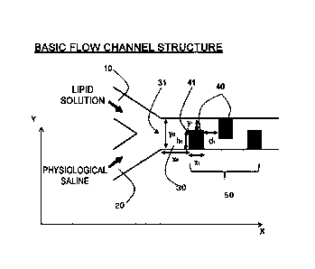
shown in Fig. 2, for example, a mutually independent first inlet channel 10
that
introduces a first fluid and a second inlet channel 20 that introduces a
second fluid
join together and have respectively fixed lengths on the upstream side thereof
(left
side in the drawing) to form a single dilution flow channel 30 towards the
downstream
side, the dilution flow channel 30 has a flow channel site that 50 is bent two-
12
CA 03059714 2019-10-10
dimensionally in at least a portion thereof, and the bent flow channel site 50
is such
that, in the case the axial direction of the dilution flow channel upstream
therefrom or
the direction in which it extends is defined as the X direction, the widthwise
direction
of the dilution flow channel that perpendicularly intersects with this X
direction is
defined as the Y direction, and the flow channel width of the dilution flow
channel
upstream therefrom is defined as yo, at least two or more structural elements
40,
which define flow channel width of the dilution flow channel by alternately
protruding
from both side surfaces of the dilution flow channel in opposition to the Y
direction
towards the center of the flow channel at a fixed height hi, h2, ... of 1/2y0
or more and
less than 1yo in an approximate Y direction (approximate +Y direction or
approximate
-Y direction) and at a fixed width xi, x2, ... in the X direction, are
provided at fixed
intervals di, d2, .... Namely, at the site where the structural elements 40
are present,
a flow channel width yi, y2, ... of the dilution flow channel is restricted to
1/2yo or less,
and particularly, 1/2yo or less to 1/40yo or more between a fixed width xi,
x2, ... in the
X direction.
[0019] Furthermore, although the flow channel structure according to the
present
invention conceptually has a form such that roughly rectangular baffles are
mutually
differently arranged from both side surfaces in the flow channel of a
microdevice as
exemplified in Fig. 2 and explained above, in actuality, the flow channel
structure is
not limited to that composed by arranging separate baffles in a flow channel
in this
manner. Namely, there are no particular limitations on the configuration of
the
structural elements 40 provided a flow channel of a similar form is formed so
as to
correspond to a flow channel formed by arranging such baffles, and as shown in
Fig.
3, for example, may be that which composes the form of a flow channel having a
two-
dimensional structure in which the walls of a flow channel structure bend in a
13
CA 03059714 2019-10-10
prescribed shape (while maintaining a nearly fixed wall thickness) while being
integrally formed to bend and expand so as to be defined as previously
described so
as to compose the structural elements 40 in the manner previously described,
and
such an aspect is naturally included in the flow channel structure according
to the
present invention. The configuration like that shown in Fig. 3 can be formed
relatively easily by injection molding, cast molding or molding using a three-
dimensional printer using, for example, a thermoplastic resin, thermosetting
resin,
ultraviolet curable resin or metal or vitreous material.
[0020] In the flow channel structure according to the present invention, the
formation
of a bent flow channel site 50, which is bent into a shape in which the
structural
elements 40 as described above are mutually differently arranged from walls on
both
sides of a dilution flow channel, is important in terms of enhancing dilution
efficiency
with a dilution solvent of a lipid solution or amphipathic substance solution
(and in the
following description, "a lipid solution or amphipathic substance solution"
may be
simply referred to as a "lipid solution" for the sake of simplification) and
obtaining
nano-sized lipid particles or micelles that have been controlled to a desired
particle
diameter. For example, although possible examples of shapes resembling the
arrangement of the structural elements 40 according to the present invention
include,
as shown in Fig. 8, (1) a shape such that a single structural element 40 of
the same
height but greater width is provided on one sidewall, (2) a shape such that a
plurality
of structural elements 40 of the same height are provided only on one
sidewall, and
(3) a shape such that a plurality of structural elements 40 are respectively
symmetrically arranged on both sidewalls and the height of each structural
element is
roughly half, in these forms, when compared with the bent flow channel site 50
in the
flow channel structure according to the present invention, adequate molecular
14
CA 03059714 2019-10-10
diffusion is unable to proceed in a short period of time and nano-sized lipid
particles
controlled to a desired particle diameter are unable to be obtained perhaps
due to the
flow channel structure being overly simple.
[0021] Although the flow channel width yo of the dilution flow channel 30
after the
first inlet channel 10 and the second inlet channel 20 have joined together is
influenced to a certain degree by the size of the particle diameter of the
nano-sized
lipid particles to be formed, this value is typically about 20 p.m to
10001.Lrn and more
preferably about 100 pirn to 200 rim. In terms of obtaining desired nano-sized
lipid
particles, and more specifically, lipid particles having a particle diameter
of a size that
is within the particle diameter range of, for example, about 10 nm to 100 nm,
diluting
the lipid solution with a dilution medium at the flow channel width yo within
the range
described above is, to a certain degree, a required condition.
[0022] Next, although the number of the structural elements 40 arranged in
plurality
in the flow channel structure according to the present invention in order to
form the
bent flow channel site 50 that provides a site for substantial molecular
diffusion is
influenced by other conditions such as the size of the lipid particles to be
obtained,
the height hi, h2, ... (length in Y direction) and width xi, X2, ... (length
in X direction) of
each of the structural elements 40, and distance di, d2, ... between each
adjacent
structural element 40, at least 2 or more, preferably 10 or more and more
preferably
about 10 to 100 are desirable since lipid particles of an intended size can be
formed.
Furthermore, there are no particular limitations on the upper limit of the
number of
structural elements 40 from the viewpoint of forming lipid particles of a
prescribed
particle size, and in principle, for example, 1000 or more or even 10000 or
more still
make it possible to form similar lipid particles of a prescribed particle
size. However,
if that number is extremely large, the flow channel structure is not very
practical from
CA 03059714 2019-10-10
the viewpoints of causing an increase in fluid resistance during the flow of
feedstock
and an increase in fabrication costs of the flow channel structure.
[0023] In addition, the height hi, h2, ... (length in the Y direction) of each
structural
element 40 is 1/2yo or more and less than 1yo, preferably 1/2yo or more and
39/40yo
or less, and even more preferably 1/2yo or more and 3/4yo or less relative to
the flow
channel width yo of the dilution flow channel 30 on the upstream side
therefrom, and
due to the presence of each structural element 40, flow channel width yi,y2,
... is
decreased from the flow channel width yo of the dilution flow channel 30 on
the
upstream side therefrom to a width of less than 1/2y0 and greater than 0.
Furthermore, the respective height hi, h2, ... of the plurality of structural
elements 40
provided in the bent flow channel site 50 is not necessarily required to be
the same,
but rather may each be different provided the above-mentioned prescribed
conditions
are satisfied. The flow channel widths yi, y2, ... formed as a result thereof
may also
each be different. For example, an aspect may be employed in which the each
width hi, h2, ... of each structural element 40 may gradually become longer
and flow
channel width yi, y2, ... may become narrower moving in the downstream
direction.
The efficiency of molecular diffusion improves as a result of the height hi,
h2,
(length in Y direction) of each structural element 40 being a prescribed
height and the
flow channel widths yi, y2, ... of the sites where these structural elements
40 are
present being held to a width of less than 1/2yo.
[0024] Although influenced by other conditions such as the size of the lipid
particles
to be obtained, the number of structural elements 40, the width xi, x2, ...
(length in the
X direction) of each mixer structural element 40 or the distance di, d2, ...
between
each adjacent structural element 40, and there are no particular limitations
thereon,
more specifically, in the case, for example, the flow channel width yo of the
upstream
16
=
CA 03059714 2019-10-10
dilution flow channel is 200 pm, then the respective height hi, h2, ... of the
structural
elements 40 is preferably 100 p.m to less than 200 pm. Thus, the flow channel
width
Y2, ... at the location where each structural element 40 is present is roughly
less
than 100 m, which is less than 1/2y0 and greater than 0.
[0025] In addition, although influenced by other conditions such as the size
of the
lipid particles to be obtained, the number of the structural elements 40, the
height hi,
h2, ... (length in the Y direction) of each structural element 40 or the
interval di, d2,
between each adjacent structural element 40, the width xi, x2, ... (length in
the X
direction) of each structural element 40 is preferably a length of about 1 /1
Oyo or more
and 5yo or less relative to the flow channel width yo of the upstream dilution
flow
channel. More specifically, in the case, for example, the flow channel width
yo of the
upstream dilution flow channel is 20 m to 1000 pm, and typically 200 p.m, the
respective width xi, x2, ... of the structural elements 40 is preferably about
20 p.m to
1000 p.m. The respective width xi, x2, ... of each structural element 40 is
not
necessarily required to be the same and may each be different provided the
above-
mentioned prescribed conditions are satisfied. For example, an aspect may be
employed in which the width xi, x2, ... gradually becomes longer moving in the
downstream direction.
[0026] In addition, although influenced by other conditions such as the size
of the
lipid particles to be obtained, the number of the structural elements 40, the
height hi,
h2, ... (length in the Y direction) of each structural element 40 or the width
xi, x2, ...
(length in the X direction) of each adjacent structural element 40, the
interval di,
d2, ... between each adjacent structural element 40 is preferably a length of
about
1/10yo or more and 5yo or less relative to the flow channel width yo of the
upstream
dilution flow channel. More specifically, in the case, for example, the flow
channel
17
CA 03059714 2019-10-10
width yo of the upstream dilution flow channel is 20 p.m to 1000 p.m, and
typically 200
pm, the interval di, d2, ... between each adjacent structural element 40 is
preferably
about 20 m to 1000 p.m. The interval di, d2, ... between each adjacent
structural
element 40 is not necessarily required to be the same and may each be
different
provided the above-mentioned prescribed conditions are satisfied. For example,
an
aspect may be employed in which the interval di, d2, ... gradually becomes
narrower
moving in the downstream direction.
[0027] Furthermore, in the flow channel structure according to the present
invention,
in the case the axial direction of the upstream dilution flow channel or
direction in
which it extends is defined as the X direction and the widthwise direction of
the
dilution flow channel that intersects perpendicularly with this X direction is
defined as
the Y direction, although each structural element 40 is alternately extended
from both
sidewalls towards the center of the flow channel in an approximate Y direction
(approximate +Y direction or approximate -Y direction) and the sidewalls are
roughly
at a right angle to the flow channel direction (X direction), this angle is
not necessarily
required to be 90 , but rather an effective configuration can be obtained even
if
inclined to a certain degree, and although there are no particular limitations
thereon,
more specifically, this angle is, for example, allowed to be within the range
of about
30 to 150 , more preferably 40 to 140 and particularly preferably 80 to
100 .
Moreover, the shape of the corner portion of each structural element 40 in the
center
of the flow channel is permitted to be rounded to a certain degree, and
although there
are no particular limitations thereon, there are cases in which rounding of,
for
example, R50 p.m or less and more preferably R20 pm or less is permitted.
However, in terms of obtaining uniform nano-sized lipid particles with a
higher degree
of controllability, these tolerances are preferably as small as possible. In
addition, in
18
=
CA 03059714 2019-10-10
the embodiments shown in Figs. 2 and 3, although X direction, which is the
axial
direction of the upstream dilution flow channel in the flow channel structure
or the
direction in which it extends, is represented with a straight line for the
sake of
convenience, this X direction merely indicates the axial direction of the
dilution flow
channel, and in actuality, is not limited to this straight line, but rather
may also, for
example, be curved at a certain curvature. Furthermore, in such cases, the Y
direction, which is the widthwise direction of the dilution flow channel that
perpendicularly intersects this X direction, indicates a direction
perpendicular to the X
direction at a site of that unit length.
[0028] In addition, since the flow channel structure according to the present
invention is a flow channel structure having a two-dimensional structure as
previously
described, the size in the direction of depth of the flow channel thereof
(direction of
paper thickness in Figs. 2 and 3) is, for example, about 10 pm to 1000 pm and
more
preferably about 50 pm to 200 i.trn, although there are no particular
limitations
thereon.
[0029] Moreover, in the flow channel structure according to the present
invention,
the angle at which the first inlet channel 10 and the second inlet channel 20
join
together may be a relatively obtuse angle, although there are no particular
limitations
thereon. Namely, in the formation of nano-sized lipid particles, since the
flow rate of
the merging fluids is quite fast, in the flow channel structure of the present
invention,
the merging angle of the first inlet channel 10 and the second inlet channel
20 does
not have an extraordinarily large effect in terms of forming uniform nano-
sized lipid
particles. Although there are no particular limitations thereon, the merging
angle is
specifically within the range of about 10 to 180 .
[0030] In the flow channel structure according to the present invention for
forming
19
85661741
nano-sized lipid particles, either one of a first fluid that is introduced
into the first inlet
channel 10 or a second fluid that is introduced into the second inlet channel
20 is a
lipid solution while the other is a dilution medium, and there are no
particular
limitations thereon. However, when the flow rates of the lipid solution and
dilution
medium used are compared in terms of forming nano-sized lipid particles, the
flow
rate of the dilution medium is typically faster. Thus, in the flow channel
structure
according to the present invention, the flow of the lipid solution on the
upstream side
of the dilution flow channel 30 immediately after the first inlet channel 10
and the
second inlet channel 20 join together when viewed macroscopically flows
downstream formed as a thin layer while the flow of the dilution medium flows
downward formed as a thick layer. Consequently, in the case the second fluid
introduced from the inlet channel (second inlet channel 20) side, located on
the side
of the sidewall (lower side in Figs. 2 and 3) where the first structural
element 40 of
the bent flow channel site 50 is formed, is a lipid solution, the flow of the
lipid solution
collides considerably with the first structural element 40, thereby resulting
in the risk
of it being difficult to flow to the downward side as a result of being
hindered by the
thick flow layer of the dilution medium. Thus, an aspect is more preferably
employed in which the first fluid introduced from the side of the inlet
channel (first
inlet channel 10) located on a sidewall on the opposite side from the sidewall
(lower
side in Figs. 2 and 3) formed of the first structural element 40 of the bent
flow
channel site 50 is the lipid solution.
[0031] In addition, although there are no particular limitations on the widths
of the
first inlet channel 10 and the second inlet channel 20, since the flow channel
width yo
of the dilution flow channel 30 after they have joined together is typically
about 100
Am to 200 gm as was previously described, these widths are each preferably set
to
Date Recue/Date Received 2022-03-28
CA 03059714 2019-10-10
about 50 gm to 400 gm and more preferably set to about 50 gm to 200 gm
corresponding thereto.
[0032] Moreover, in the flow channel structure according to the present
invention, if
a distance xo from a confluence 31 of the first inlet channel 10 and the
second inlet
channel 20 to an upstream end 41 of the first structural element 40 is
extremely long,
or in other words, if excess time is required for the diluted fluid to reach
the bent flow
channel site 50 having the structural elements 40 disposed therein, there is a
tendency for the particle diameter of the lipid particles formed to become
large.
Consequently, this distance (distance xo) is preferably such that the dilution
medium
having a set flow rate passes through in 0.1 seconds or less. More
specifically, in
the case, for example, the set flow rate (total flow rate) of the dilution
medium is 1
ml/min, the distance xo is preferably set to about 80 mm or less.
[0033] Moreover, in the flow channel structure according to the present
invention,
there are no particular limitations on the respective number of the first
inlet channel
and the second inlet channel 20, a plurality of each can be provided. In
particular, there are cases in which an aspect can be employed in which a
plurality of
inlet channels is preferably provided on the side where the dilution medium
flows,
which typically has a faster flow rate in comparison with the lipid solution.
Namely,
this is because, as a result of providing a plurality of inlet channels on the
side where
the dilution medium flows in this manner, even if the lipid solution flows at
a relatively
slow flow rate, there are cases in which the particle diameter of the formed
lipid
particles and the standard deviation thereof can be made to be smaller values
with
favorable controllability.
[0034] Although there are no particular limitations thereon, Fig. 18 shows an
example of an embodiment having such a plurality of second inlet channels
(and/or
21
CA 03059714 2019-10-10
first inlet channels) of the flow channel structure according to the present
invention in
which the structure has a single inlet channel for the first inlet channel 10,
which
introduces a lipid solution as a first fluid, and two inlet channels 20a and
20b for the
second inlet channel 20, which introduces the dilution medium as a second
fluid. In
the example shown in Fig. 18, although the two second inlet channels 20a and
20b
respectively join together from both sides at a relatively acute angle with
respect to
the central first inlet channel 10, even in a form having a plurality of
second inlet
channels (and/or first inlet channels) in this manner, there are no particular
limitations
on the angle at which the first inlet channel and second inlet channels join
together
and may join together at a relatively obtuse angle as previously described.
[0035] In addition, in a form having a plurality of second inlet channels
(and/or first
inlet channels) in this manner, there are no particular limitations on the
flow rate ratio
of the fluids flowing through each of the plurality of second inlet channels
(and/or first
inlet channels), or in other words, there are no particular limitations on the
flow rate
ratio of the dilution medium respectively flowing through the two second inlet
channels 20a and 20b in the case of the example shown in Fig. 18, for example.
Namely, since the flow channel structure according to the present invention
functions
effectively even if each fluid is allowed to flow from that in which there is
only one
each of the first and second inlet channels, in the case of having a plurality
of each
inlet channel, the mutual flow rate ratio of the same type of a plurality of
inlet
channels can be arbitrary and that flow rate ratio is not limited to 1:1, or
in other
words, an aspect in which equal amounts each flow from a plurality of inlet
channels,
but rather can be suitably altered as necessary in consideration of the
particle
diameter and so forth of the lipid particles to be obtained. Furthermore, if
the
configuration of the bent flow channel site 50 having the flow channel
structure
22
CA 03059714 2019-10-10
according to the present invention employs a preferable aspect, as is
indicated in the
examples to be subsequently described, if the flow rate ratio of the dilution
medium is
within the range of about 1:1 to 1:10 in the case there are a plurality (two)
of second
inlet channels introducing the dilution medium, there are is no large effect
on particle
diameter of the formed lipid particles, and the particle diameter and standard
deviation thereof of the formed lipid particles can be made to be of smaller
values
with favorable controllability within this range.
[0036] Moreover, although the flow channel structure according to the present
invention is a flow channel structure for forming nano-sized lipid particles
or micelles
of amphipathic substances such as amphipathic polymers as was previously
described, in the case of enclosing a core particle demonstrating a capsule
structure
similar to the bent flow channel site, for example, as a contained
physiologically
active substance like that to be subsequently described within this nano-sized
lipid
particle or micelle of an amphipathic substance such as an amphipathic
polymer, a
flow channel having a similar structure to the flow channel structure having a
bent
flow channel site according to the present invention as previously described
can be
provided as a flow channel for a pretreatment process for forming this core
particle,
and the second inlet channel (or first inlet channel) can be composed by
connecting
to the downstream side of this flow channel for a pretreatment process.
Furthermore, the connected inlet channel is inherently a flow channel used as
the
side where the dilution medium is introduced. Fig. 25(a) schematically shows
this
type of configuration, and as indicated in the drawing, the overall flow
channel has a
form such that bent flow channel sites have been combined in multiple stages.
As a
result of using this aspect of a structure having a multistage bent flow
channel site in
this manner, the inclusion of a physiologically active substance as a core
particle
23
CA 03059714 2019-10-10
demonstrating a capsule structure within a nano-sized lipid particle or
micelle of an
amphipathic substance such as an amphipathic polymer can be prepared by a
series
of procedures. Furthermore, the bent flow channel site for a pretreatment
process
and the bent flow channel site for the main process of forming a lipid
particle or
micelle are only the same in the sense that they both satisfy the above-
mentioned
regulatory conditions, or in other words, in the case the axial direction of
the dilution
flow channel upstream therefrom or the direction in which it extends is
defined as the
X direction, the widthwise direction of the dilution flow channel that
perpendicularly
intersects with this X direction is defined as the Y direction, and the flow
channel
width of the dilution flow channel upstream therefrom is defined as yo, at
least two or
more structural elements 40, which define flow channel width of the dilution
flow
channel by alternately protruding from both side surfaces of the dilution flow
channel
in opposition to the Y direction towards the center of the flow channel at a
fixed
height hi, h2, ... of 1/2y0 or more and less than lyo in an approximate Y
direction
(approximate +Y direction or approximate -Y direction) and at a fixed width
xi, x2, ...
in the X direction, are provided at fixed intervals di, d2, ..., and are not
limited to an
aspect in which both have completely identical structures. The arrangement,
number and size of these structural elements along with the flow speed
conditions of
the fluid can be set to conditions corresponding to each site corresponding to
the
prescribed particle diameter to be formed in each flow channel site, the
material used
and so forth. Furthermore, conditions such as the arrangement, number and size
of
the structural elements, the width of the dilution flow channel and the number
of inlet
channels used in the flow channel structure used as a flow channel for a
pretreatment process are the same as those explained relating to the
previously
described original flow channel structure for forming lipid particles or
micelles, and an
24
CA 03059714 2019-10-10
explanation thereof has been omitted.
[0037] Next, an explanation is provided of the lipid particle or micelle
formation
method according to the present invention. The lipid particle formation method
according to the present invention is characterized in that, a lipid solution
or
amphipathic substance solution is introduced from one of the first inlet
channel 10
and the second inlet channel 20 of a flow channel structure while a dilution
solvent is
introduced from the other inlet channel at a total flow rate of 1 gmin to 100
ml/min
using this flow channel structure.
[0038] According to this method, lipid particles or micelles of an amphipathic
substance can be prepared of a desired size, and more specifically, an
arbitrary size
within the range of a particle diameter of, for example, about 10 nm to 100
nm, and
the produced lipid particles or micelles can be preferably used, for example,
as
nanocarriers for an efficient drug delivery system (DDS).
[0039] Although as previously described, the flow channel structure used in
the lipid
particle formation method of the present invention is characterized in that,
by making
the number of structural elements 40, the height hi, h2, ... (length in the Y
direction) of
each structural element 40, the width xi, x2, ... (length in the X direction)
of each
structural element 40 and the interval di, d2, ... between each adjacent
structural
element 40 to be within prescribed ranges, the range of particle diameter of
the lipid
particles formed can be changed to be within a prescribed range, and by
further
adjusting the flow rate and dilution factor of a feedstock solution, desired
nano-sized
lipid particles can be formed with favorable controllability.
[0040] Furthermore, in the case of using a conventional microdevice, although
lipid
particles of a particle diameter of about 20 nm, which was theoretically the
smallest
size at which lipid particles were able to be formed, were unable to be formed
unless
CA 03059714 2019-10-10
the solution was fed at a considerably high flow rate of, for example, about 5
ml/min,
in the present invention, use of the flow channel structure according to the
present
invention as previously described makes it possible to prepared lipid
particles having
a particle diameter of about 20 nm with favorable controllability even if
solution is fed
at a lower flow rate of, for example, 500
[0041] In the lipid particle formation method of the present invention,
although the
total flow rate of the lipid solution and dilution solvent fed to the above-
mentioned
flow channel structure is suitably adjusted within a range of 1 [11/min to 100
ml/min as
previously described corresponding to the size of the lipid particles to be
formed and
differences in the configuration of the flow channel structure, from the
viewpoint of
controllability of particle diameter, the total flow rate is more preferably
within the
range of 50 p.1/min to 500 RI/min.
[0042] There are no particular limitations on the compositions of the lipid
solution
and dilution medium used in the lipid particle formation method of the present
invention or on the resulting dilution factors thereof. In principle, the
lipid particle or
micelle formation method of the present invention forms lipid particles,
including
liposomes, or micelles of an amphipathic substance by adding a solution
obtained by
dissolving a lipid or amphipathic substance in a water-miscible organic
solvent under
warming conditions as necessary to an aqueous solution (dilution medium) and
diluting therewith, and a conventionally known composition and the like can be
used
in this method.
[0043] Although there are no particular limitations thereon, one or two or
more lipids,
such as soybean lecithin, hydrogenated soybean lecithin, egg yolk lecithin,
phosphatidylcholines, phosphatidylserines, phosphatidylethanolamines,
phosphatidylinositols, phosphasphingomyelins, phosphatidic acids, long chain
alkyl
26
CA 03059714 2019-10-10
phosphates, gangliosides, glycolipids, phosphatidylglycerols or sterols, can
be used
for the lipid component contained in the lipid solution. In an aspect in which
lipid
particles are used as carriers for a drug delivery system (DDS), a preferable
example
thereof consists of the use of a combination of phospholipid and cholesterol,
as lipids
constituting lipid particles (such as liposomes), and particularly, a
combination of a
phosphatidylcholine, which is a type of phospholipid, and cholesterol.
[0044] In addition, although there are no particular limitations thereon,
examples of
amphipathic substances include amphipathic polymer compounds such as
amphipathic block copolymers in the manner of polystyrene-polyethylene oxide
block
copolymer, polyethylene oxide-polypropylene oxide block copolymer, polylactic
acid-
polyethylene glycol copolymer and polycaprolactone-polyethylene glycol
copolymer.
[0045] Although there are no particular limitations thereon, organic solvents
that are
miscible in water, such as alcohols, ethers, esters, ketones or acetals, and
particularly, alcohols such as ethanol, t-butanol, 1-propanol, 2-propanol or 2-
butoxyethanol, are preferably used for the water-miscible organic solvent used
to
prepare the lipid solution by dissolving a lipid as previously described. In
addition,
although similar substances can be used for the water-miscible organic solvent
used
to prepare the amphipathic substance solution, preferable examples thereof
include
ethers such as tetrahydrofuran and chloroform.
[0046] On the other hand, an aqueous solution such as physiological saline,
phosphate buffer solution, acetate buffer solution, or citrate buffer
solution, having
water or basically having water as the main component thereof, is suitably
used for
the dilution medium corresponding to the application of the lipid particles to
be
formed.
[0047] In addition, a physiologically active substance can be incorporated in
the lipid
27
CA 03059714 2019-10-10
particle or micelle as is commonly known corresponding to the application of
the
resulting lipid particle or micelle. Although there are no particular
limitations
thereon, examples thereof include drugs, physiological active substances, and
cosmetics such as an anticancer drug, antioxidant, antimicrobial agent, anti-
inflammatory agent, vitamin, hemoglobin, DNA, RNA, peptide, protein, vaccine,
hair
growth agent, moisturizer, pigment, whitening agent or colorant. These
additives
can be contained in the aqueous phase of the lipid particle or micelle formed
by
incorporating in the above-mentioned dilution medium provided they are water-
soluble. In addition, these additives can be incorporated in the lipid
membrane of
the lipid particle provided they are lipid-soluble. Moreover, a drug,
physiologically
active substance or cosmetic and the like, for example, can be incorporated in
a lipid
particle or micelle formed according to the present invention in the form of a
particle
(core particle) in which these additives are dispersed in the aqueous phase.
[0048] In addition, the surface of a lipid particle can be modified with a
functional
group and the like as is commonly known in the art. Modification by a
functional
group can be realized by preliminarily bonding a functional group to a
phospholipid
and the like or by bonding the functional group after having formed the lipid
particle.
Furthermore, there are no particular limitations on the concentration of water-
miscible
organic solvent in the above-mentioned lipid solution or on the blending ratio
of the
dilution medium used to dilute the lipid solution provided it is within a
suitable range
dependent on the lipid composition or lipid concentration so that a lipid
particle
(liposome) is formed as is commonly known in the art.
[0049] Furthermore, in the lipid particle of micelle formation method
according to the
present invention, since a lipid solution or amphipathic substance is diluted
with a
dilution medium using the flow channel structure as previously described,
there are
28
CA 03059714 2019-10-10
no particular limitations thereon, and although influenced to a certain degree
by the
type of lipid or amphipathic substance and the type of water-miscible organic
solvent
used, more specifically, the ratio of the flow rate of the lipid solution or
amphipathic
substance solution to the flow rate of the dilution medium is about 1:1 to
1:50 and
more preferably about 1:3 to 1:10 in terms of obtaining favorable dispersion
efficiency.
Examples
[0050] Although the following provides a more detailed explanation of the
present
invention based on examples thereof, the present invention is not limited in
any way
to these examples.
[0051] Example 1
The effect of the number of structural elements 40 required to produce
desired nano-sized lipid particles in a flow channel structure having the
basic
structure shown in Fig. 2 was investigated.
Flow channel structures were fabricated in which the number of structural
elements 40 was 6, 10, 20 and 100, respectively while using the same
parameters of
flow channel width yo = 200 gm, height hi, h2, ... (length in Y direction) of
each
structural element 40 = 1501.1m, width xi, x2, ... (length in X direction) of
each
structural element 40 = 100 gm and interval di, d2, ... between each adjacent
structural element 40 = 100 gm. A lipid solution (10 mg/ml of
phosphatidylcholine
solution in ethanol) was introduced from the first inlet channel 10 of these
flow
channel structures and physiological saline was introduced from the second
inlet
channel at a flow rate ratio of 1:3 or 1:9 while adjusting to a prescribed
total flow rate,
followed by forming lipid particles and investigating the particle diameter of
the
resulting lipid particles. The results are shown in Fig. 4. As shown in Fig.
4,
29
CA 03059714 2019-10-10
although nano-sized lipid particles were able to be formed under any of the
conditions, particles of a target size within the range of 20 nm to 100 nm
were able to
be formed with favorable controllability if the number of structural elements
40 was
or more in particular.
[0052] Example 2
The interval di, d2, ... between adjacent structural elements 40 required to
produce desired nano-sized lipid particles in a flow channel structure having
the
basic structure shown in Fig. 2 was investigated.
Flow channel structures were fabricated in which the interval di, d2,
between adjacent structural elements 40 was 100 1.1.m, 200 p.m, 500 IAM or 1
mm,
respectively, while using the same parameters of flow channel width yo = 200
m,
number of structural elements 40 = 100, height hi, h2, ... (length in Y
direction) of
each structural element 40 = 150 m and width xi, x2, ... (length in X
direction) of
each structural element 40 = 100 p.m. A lipid solution (10 mg/ml of
phosphatidylcholine solution in ethanol) was introduced from the first inlet
channel 10
of these flow channel structures and physiological saline was introduced from
the
second inlet channel at a flow rate ratio of 1:3 or 1:9 while adjusting to a
prescribed
total flow rate, followed by forming lipid particles and investigating the
particle
diameter of the resulting lipid particles. Furthermore, a similar test was
carried out
in the absence of structural elements 40 and using a conventionally known
chaotic
mixer in a flow channel structure of the same flow channel width for reference
purposes. Furthermore, the same chaotic mixer in accordance with the contents
described in the above-mentioned NPL 1 (chaotic mixer having a width of 50 pm
and
depth of 31 m arranged for 69 cycles in a flow channel having a diameter of
200
m) was fabricated and used in the above-mentioned test (the description of the
=
CA 03059714 2019-10-10
relevant portion of NPL 1 is included in the present description in connection
therewith). The results are shown in Fig. 5. As shown in Fig. 5, although nano-
sized lipid particles were able to be formed under any of the conditions,
particles of a
target size within the range of 10 nm to 100 nm were able to be formed with
favorable controllability if the interval di, d2, ... between adjacent
structural elements
40 was 500 um or less in particular.
[0053] Example 3
The effect of height hi, h2, ... (length in Y direction) of each structural
element
40 required to produce desired nano-sized lipid particles in a flow channel
structure
having the basic structure shown in Fig. 2 was investigated.
Flow channel structures were fabricated in which the height hi, h2, ...
(length
in Y direction) of each structural element 40 was 70 um, 100 1.1.m or 150 um
while
using the same parameters of flow channel width yo = 200 um, number of
structural
elements 40 = 100, width xi, x2, ... (length.in X direction) of each
structural element
40 = 100 um, and interval di, d2, ... between adjacent structural elements 40
= 100
um. A lipid 'solution (10 mg/ml of phosphatidylcholine solution in ethanol)
was
introduced from the first inlet channel 10 of these flow channel structures
and
physiological saline was introduced from the second inlet channel at a flow
rate ratio
of 1:3 or 1:9 while adjusting to a prescribed total flow rate, followed by
forming lipid
particles and investigating the particle diameter of the resulting lipid
particles.
Furthermore, a similar test was carried out in the absence of structural
elements 40
and using a conventionally known chaotic mixer (same as that used in Example
2) in
a flow channel structure of the same flow channel width for reference
purposes.
The results are shown in Fig. 6. As shown in Fig. 6, particles of a target
size within
the range of 10 nm to 100 nm were able to be formed with favorable
controllability if
31
CA 03059714 2019-10-10
=
the height hi, h2, ... (length in Y direction) of each structural element 40
was 100 gm.
[0054] Example 4
The effect of width xi, x2, ... (length in X direction) of each structural
element
40 required to produce desired nano-sized lipid particles in a flow channel
structure
having the basic structure shown in Fig. 2 was investigated.
Flow channel structures were fabricated in which the width xi, x2, ... (length
in
X direction) of each structural element 40 was 50 gm, 70 gm or 100 gm while
using
the same parameters of flow channel width yo = 200 gm, number of structural
elements 40 = 100, height hi, h2, ... (length in Y direction) of each
structural element
40 = 150 gm and interval di, d2, ... between adjacent structural elements 40 =
100
gm. A lipid solution (10 mg/ml of phosphatidylcholine solution in ethanol)
was
introduced from the first inlet channel 10 of these flow channel structures
and
physiological saline was introduced from the second inlet channel at a flow
rate ratio
of 1:3 or 1:9 while adjusting to a prescribed total flow rate, followed by
forming lipid
particles and investigating the particle diameter of the resulting lipid
particles.
Furthermore, a similar test was carried out in the absence of structural
elements 40
and using a conventionally known chaotic mixer (same as that used in Example
2) in
a flow channel structure of the same flow channel width for reference
purposes.
The results are shown in Fig. 7. As shown in Fig. 7, although nano-sized lipid
particles were able to be formed under any of the conditions, particles of a
target size
within the range of 10 nm to 100 nm were able to be formed with favorable
controllability if the width xi, x2, ... (length in X direction) of each
structural element 40
was 100 grn in particular.
[0055] Example 5
A flow channel structure having the basic structure according to the present
32
=
CA 03059714 2019-10-10
invention as shown in Fig. 8 (flow channel width yo = 200 gm, number of
structural
elements 40 = 100, height hi, h2, ... (length in Y direction) of each
structural element
40 = 150 gm, width xi, x2 (length in X direction) of each structural element
40 = 100
gm and interval di, d2, ... between adjacent structural elements 40 = 100 gm)
along
with flow channel structures having (1) a shape such that a single structural
element
40 of the same height but larger width is provided on one sidewall, (2) a
shape such
that a plurality of structural elements 40 of the same height are provided on
only one
sidewall, and (3) a shape such that a plurality of structural elements 40 are
provided
on both sidewalls but are each arranged symmetrically and the height of each
structural element is half, were respectively fabricated followed by
investigating the
effect of the structural elements in terms of producing desired nano-sized
lipid
particles. The results are shown in Fig. 9. As shown in Fig. 9, only the flow
channel structure having the basic structure according to the present
invention was
able to form lipid particles of a target size with favorable controllability.
[0056] Example 6
In order to simulate the diluted state of a lipid solution in a flow channel
structure having the basic structure according to the present invention,
ethanol,
which is a water-miscible organic solvent of the lipid solution, and water as
a dilution
solvent, were allowed to flow into the flow channel structure at a flow rate
ratio of 1:3
and total flow rate of 50 gl/min followed by simulating the flow thereof with
the
COMSOL Multiphysics general-purpose physics simulation software. The results
are shown in Fig. 10. As shown in Fig. 10, the lipid solution was diluted and
dispersed due to the presence of the structural elements, and dispersion was
confirmed to proceed considerably uniformly when the number thereof was 10 in
particular.
33
CA 03059714 2019-10-10
[0057] Example 7
In order to investigate the effect of the length of distance xo from the
confluence 31 of the first inlet channel 10 and the second inlet channel 20 to
the
upstream end 41 of the first structural element 40 on the particle diameter of
lipid
particles, flow channel structures were fabricated while respectively changing
that
distance xo to 30 mm, 50 mm, 65 mm, 80 mm or 100 mm in a flow channel
structures
having the basic structure according to the present invention. Furthermore,
the
parameters of flow channel width yo = 200 Rrn, number of structural elements
40 =
100, height hi, h2, ... (length in Y direction) of each structural element 40
= 150
width xi, x2 (length in X direction) of each structural element 40 = 100 jim
and interval
di, d2, ... between adjacent structural elements 40 = 100 gm of these flow
channel
structures were the same for each flow channel structure.
A 10 mg/ml phospholipid/ethanol solution as lipid solution was allowed to flow
in at a flow rate of 0.1 ml/min and physiological saline as a dilution medium
was
allowed to flow in at a flow rate of 0.9 ml/min (total flow rate: 1.0 ml/min)
followed by
a comparison of particle diameter of the formed lipid particles. Furthermore,
Fig. 11
schematically indicates the relationship between distance from the confluence
31 and
time required to reach that point in the case of having allowed the lipid
solution and
dilution solvent to flow at this total flow rate. The results obtained are
shown in Fig.
12. As shown in Fig. 12, the particle diameter of the resulting lipid
particles ended
up increasing if the distance xo was 80 mm or more (transit time: about 0.1
seconds
or more). On the other hand, favorable particle diameter was obtained if the
distance xo was 65 mm or less (transit time: about 0.08 seconds or less).
[0058] Example 8
Lipid particles composed of a pH-responsive cationic lipid (YSK05),
34
=
CA 03059714 2019-10-10
= =
cholesterol, polyethylene glycol lipid and siRNA were attempted to be produced
by
allowing lipid solutions having a lipid composition consisting of a pH
responsive
cationic lipid (YSK05), cholesterol and polyethylene glycol lipid (ratio of
YSK05/cholesterol/mPEG2k-DMG = 70/30/1-3 (mol%)) (8 mM lipid concentration in
ethanol) and an siRNA solution as a dilution medium (25 mM acetate buffer, pH
4.0)
into a flow channel structure having the basic structure according to the
present
invention (flow channel width yo = 200 m, number of structural elements 40 =
100,
height hi, h2, ... (length in Y direction) of each structural element 40 = 150
m, width
xi, x2, (length in X direction) of each structural element 40 = 100 j.m and
interval di,
d2, ... between adjacent structural elements 40 = 1001.1m) at a flow rate of
ratio 1:3
and total flow speed of 500 I/min. As a result, as shown in Fig. 13, lipid
nanoparticles of a highly uniform size and having a particle diameter of 100
nm or
less were able to be confirmed to be formed.
[0059] Each of the produced lipid nanoparticles was administered intravenously
to
4-week-old ICR mice at a ratio of 0.1 mg (siRNA)/kg (body weight) or 0.4 mg
(siRNA)/kg (body weight) followed by observing gene knockdown activity in
liver
parenchymal cells and localization of the administered drugs in the liver.
Gene
knockdown activity in liver parenchymal cells was determined by collecting
blood 24
hours after intravenous administration and investigating factor VII (F7)
activity in
plasma. Localization in the liver was observed by observing each site in the
liver 30
minutes after intravenous administration with a confocal laser scanning
microscope.
Furthermore, lipid nanoparticles in which the lipid was fluorescent-labeled
with Dil
(0.5 mol%) were used for the lipid particles used to observe localization in
the liver.
The results obtained are shown in Figs. 14 and 15. As shown in Fig. 14, lipid
particles produced using the flow channel structure according to the present
=
CA 03059714 2019-10-10
=
invention favorably demonstrated dose-dependent gene knockdown activity in
vivo,
and 1% PEG in particular, having a large particle diameter, exhibited high
activity
(about 3-fold). In addition, as shown in Fig. 15, lipid particles produced
using the
flow channel structure according to the present invention demonstrated a
favorable
drug delivery action in vivo, and 3% PEG in particular, having a small
particle
diameter, demonstrated little non-specific accumulation in the blood and
selectively
reached the liver parenchymal cells (deep tissue).
[0060] Example 9
The effect of flow channel width yo required to produce lipid nanoparticles of
a desired size in the flow channel structure according to the present
invention was
investigated.
As shown in Fig. 16(a), flow channel structures were respectively prepared
consisting of the flow channel structure having the basic structure according
to the
present invention (flow channel width yo = 200 pm, number of structural
elements 40
= 100, height hi, h2, ... (length in Y direction) of each structural element
40 = 150 p,M,
width xi, x2 (length in X direction) = 100 fim and interval di, d2, ...
between adjacent
structural elements 40 = 100 p.m), along with (1) a flow channel structure in
which
flow channel width yo = 400 pm, number of structural elements 40 = 100, height
hi,
h2, ... (length in Y direction) of each structural element 40 = 300 m, width
xi, x2
(length in X direction) = 100 rn and interval di, d2, ... between adjacent
structural
elements 40 = 100 [am with the flow channel width being wider than the flow
channel
structure of the above-mentioned basic structure, but the ratio of the flow
channel
width yo to the height hi, h2, ... (length in Y direction) of each structural
element 40
being the same at 4:3, and (2) a flow channel structure in which flow channel
width yo
= 400 tim, number of structural elements 40 = 100, height hi, h2, ... (length
in Y
36
= =
CA 03059714 2019-10-10
direction) of each structural element 40 = 350 ion, width xi, x2 (length in X
direction)
= 100 gm and interval di, d2, ... between adjacent structural elements 40 =
100 tim,
with the flow channel width being wider than the flow channel structure of the
above-
mentioned basic structure and the ratio of flow path width yo to the height
hi, h2,
(length in Y direction) of each structural element 40 being made to be 8:7.
A lipid solution (10 mg/ml of phosphatidylcholine solution in ethanol) was
introduced from the first inlet channel 10 of these flow channel structures
and
physiological saline was introduced from the second inlet channel at a flow
rate ratio
of 1:9 while adjusting to a prescribed total flow rate, followed by forming
lipid particles
and investigating the particle diameter of the resulting lipid particles.
Furthermore, a
similar test was carried out in a flow channel structure of the same flow
channel width
but not having structural elements 40 and the results are shown in Fig. 16. As
shown in Figs. 6(b) and 6(c), there was no large effect on controllability of
particle
diameter even if the flow channel width yo was increased to 400 rn. In
addition, the
flow channel structure in which the ratio of the flow channel width yo to the
height hi,
h2, ... (length in Y direction) of each structural element 40 was 4:3 allowed
the
obtaining of more favorable results than in the case of a ratio of 8:7 with
respect to
somewhat better controllability of particle diameter.
[0061] Example 10
The effect of the inclination of each structural element in the flow channel
structure according to the present invention was investigated.
Flow channel structures were fabricated that were composed such that the
angle 0 formed between the wall surface of each structural element and the
direction
of the flow channel (X direction) was 40 , 50 , 60 , 70 , 80 , 90 , 100 , 110
, 120 ,
130 or 140 (90 50 ) in flow channel structures having the basic
configuration of
37
=
CA 03059714 2019-10-10
flow channel width yo = 200 m, number of structural elements 40 = 100, height
hi,
h2, ... (length in Y direction) of each structural element 40 = 150 m, width
xi, x2
(length in X direction) = 100 pm and interval di, d2, ... between adjacent
structural
elements 40 = 100 m as shown in Fig. 17(a).
A lipid solution (10 mg/ml of phosphatidylcholine solution in ethanol) was
introduced from the first inlet channel 10 of these flow channel structures
and
physiological saline was introduced from the second inlet channel at a flow
rate ratio
of 1:3 or 1:9 while adjusting to a prescribed total flow rate of 50 pl/min,
100 I/min or
500 I/min, followed by forming lipid particles and investigating the particle
diameter
of the resulting lipid particles. The results are shown in Figs. 17(b) and
17(c). As
shown in Figs. 17(b) and 17(c), lipid particles having a prescribed particle
diameter
were able to be similarly formed even if the wall surface of each structural
element
was inclined within the range of about 90 50 in the direction of the flow
channel (X
direction), and the particle diameter of the lipid particles was able to be
confirmed to
be controllable according to flow rate conditions.
[0062] Example 11
The effect of the number of fluid inlet channels in the flow channel structure
according to the present invention was investigated. Flow channel structures
were
separately prepared having the same structure as the flow channel structure
having
the basic structure according to the present invention (each having one first
inlet
channel 10 and one second inlet channel 20; flow channel width yo = 200 pm,
number of structural elements 40 = 100, height hi, h2, ... (length in Y
direction) of
each structural element 40 = 150 pm, width xi, x2 (length in X direction) =
100 m
and interval di, d2, ... between adjacent structural elements 40 = 100 m)
with the
exception of having a shape in which two second fluid inlet channels 20a and
20b
38
CA 03059714 2019-10-10
join together from both sides with the central first inlet channel 10 as
schematically
shown in Fig. 18(a).
In this flow channel structure having the two second fluid inlet channels 20a
and 20b, a lipid solution (10 mg/ml phosphatidylcholine solution in ethanol)
was
introduced from the first inlet channel 10 and physiological saline was
introduced
from the second inlet channels 20a and 20b while adjusting so that the overall
flow
rate ratio of lipid solution to physiological saline was 1:3 and so that the
flow rate ratio
of the physiological saline respectively introduced from the second inlet
channel 20a
and the second inlet channel 20b was 1:1, 3:1, 1:3, 9:1 or 1:9, followed by
investigating the particle diameter of the lipid particles.
In addition, for reference purposes, a lipid solution was introduced from the
first inlet channel 10 and physiological saline was introduced from the second
inlet
channel 20 in the same manner as described above in a flow channel structure
having the basic structure according to the present invention of one each of
the first
inlet channel 10 and the second inlet channel 20 while adjusting the overall
flow rate
ratio of lipid solution to physiological saline to 1:3, 1:5, 1:7, 1:9 or 1:20,
followed by
investigating the particle diameter of the lipid particles. The results are
shown in
Figs. 18(b) and 18(c).
Fig. 18(b) is a graph indicating the effect on particle diameter of the lipid
particles of changes in the flow rate ratio of physiological saline
respectively
introduced from the second inlet channel 20a and the second inlet channel 20b
in the
flow channel structure having two second fluid inlet channels 20a and 20b.
Based
on the results shown in Fig. 18(b), results were obtained in which changes in
the flow
rate ratio of physiological saline respectively introduced from the second
inlet
channel 20a and the second inlet channel 20b in the flow channel structure
having
39
CA 03059714 2019-10-10
two second fluid inlet channels 20a and 20b did not have that large of an
effect on
particle diameter of the resulting lipid particles.
Fig. 18(c) is a graph indicating the effect on particle diameter of the lipid
particles in the case of using a flow channel structure having two second
fluid inlet
channels 20a and 20b and a flow channel structure having a single second inlet
channel 20. Based on the results shown in Fig. 18(c), it was indicated that,
as a
result of having used a plurality (two) of second fluid inlet channels 2, the
standard
deviation of particle diameter of the lipid particles formed at a low flow
rate decreased
and there was little variation in particle diameter in comparison with the
flow channel
structure only having one first inlet channel and second inlet channel each.
Furthermore, it was also indicated that, if the weight ratio of lipid solution
to
physiological saline is 1:3, the particle diameter of the resulting lipid
particles tended
to be smaller.
[0063] Example 12
The effect of the number of fluid inlet channels was investigated in aspects
of
the flow channel structure according to the present invention having different
shapes
(shape and arrangement of each structural element) of the bent flow channel
site of
the flow channel structure.
Namely, flow channel structures similar to that used in Example 11 were
prepared for use as flow channel structures consisting of: (1) flow channel
structure
having a shape in which a single first inlet channel 10 and two second fluid
inlet
channels 20a and 20b join together therewith from both sides and in which the
bent
flow channel site is that of the above-mentioned basic structure (flow channel
width
yo = 200 i.im, number of structural elements 40 = 100, height hi, h2, ...
(length in Y
direction) of each structural element 40 = 150 jim, width xi, x2 (length in X
direction)
CA 03059714 2019-10-10
=
= 100 gm and interval di, d2, ... between adjacent structural elements 40 =
100 gm),
(2) flow channel structure having a shape in which a single first inlet
channel 10 and
two second fluid inlet channels 20a and 20b join together therewith from both
sides
and in which the bent flow channel site is such that flow channel width yo =
200 gm,
number of structural elements 40 = 100, height hi, h2, ... (length in Y
direction) of
each structural element 40 = 100 gm, width xi, x2 (length in X direction) =
100 gm
and interval di, d2, ... between adjacent structural elements 40 = 100 gm, (3)
flow
channel structure having a shape in which a single first inlet channel 10 and
two
second fluid inlet channels 20a and 20b join together therewith from both
sides and
in which the bent flow channel site is such that flow channel width yo = 200
gm,
number of structural elements 40 = 100, height hi, h2, ... (length in Y
direction) of
each structural element 40 = 150 gm, width xi, x2 (length in X direction) =
100 gm
and interval di, d2, ... between adjacent structural elements 40 = 500 jtm,
(4) flow
channel structure having the basic structure according to the present
invention
(having one each of first inlet channel 10 and second inlet channel 20, and
flow
channel width yo = 200 gm, number of structural elements 40 = 100, height hi,
h2,
(length in Y direction) of each structural element 40 = 150 gm, width xi, x2
(length in
X direction) = 100 gm and interval di, d2, ... between adjacent structural
elements 40
= 100 gm), and (5) flow channel structure not having the structural elements
40 in a
flow channel structure having the same flow channel width as the flow channel
structure of (4) above provided for reference purposes.
In these five flow channel structures, a lipid solution (10 mg/ml
phosphatidylcholine solution in ethanol) was introduced from the first inlet
channel 10
and physiological saline was introduced from the second inlet channels 20a and
20b
at a total flow rate of 50 gl/min while adjusting to an overall flow rate
ratio of lipid
41
CA 03059714 2019-10-10
solution to physiological saline of 1:3 and so that, in the flow channel
structures of (1)
to (3) above, the flow rate ratio of physiological saline respectively
introduced from
the second inlet channel 20a and the second inlet channel 20b is 1:1, 3:1,
1:3, 9:1 or
1:9 followed by forming lipid particles and investigating the particle
diameter of the
resulting lipid particles. The results obtained are shown Figs. 19 and 20.
As shown in Fig. 19, in the case of using the flow channel structures of (1)
to
(3) above having a plurality (two) of second fluid inlet channels 2, the lipid
diameter
and standard deviation of the resulting lipid particles were both smaller in
each case
in comparison with the flow channel structure of (4) above which had only one
first
inlet channel and only one second inlet channel. In addition, as shown in
Figs. 19
and 20, particle diameter was indicated to undergo a relative change in the
case of
using the flow channel structures of (2) and (3) above according to the flow
rate ratio
of the physiological saline respectively introduced from the second inlet
channel 20a
and the second inlet channel 20b. On the other hand, particle diameter was
indicated as not being greatly affected by flow rate ratio in the case of
using the flow
channel structure of (1) above.
[0064] Example 13
In order to simulate the diluted state of a lipid solution in a flow channel
structure having the basic structure according to the present invention in the
same
manner as Example 6, ethanol, which is a water-miscible organic solvent of the
lipid
solution, and water as a dilution solvent, were allowed to flow into the flow
channel
structure at a flow rate ratio of 1:3 followed by simulating the flow thereof
with the
COMSOL Multiphysics general-purpose physics simulation software. Furthermore,
in order to investigate the dilution process according to differences in total
flow rate,
the total flow rate was set to 100 I/min and 5001.11/min. The results
obtained are
42
CA 03059714 2019-10-10
shown in Fig. 21. As shown in Fig. 21, a larger total flow rate was indicated
to
cause the lipid solution to be diluted more rapidly by the structural
elements.
[0065] Example 14
In order to simulate (1) the diluted state of a lipid solution in the flow
channel
structure having the basic structure according to the present invention and
(2) the
diluted state of a lipid solution in a flow channel structure having the same
structure
as the above-mentioned flow channel structure having the basic structure with
the
exception of having a shape in which two second fluid inlets channels 20a and
20b
join together with a central first inlet channel 10 in the same manner as that
used in
the above-mentioned Example 10, ethanol, which is a water-miscible organic
solvent
of the lipid solution, and water as a dilution solvent, were allowed to flow
into the flow
channel structure at a flow rate ratio of 1:3 and total flow rate of 50
til/min followed by
simulating the flow thereof with the COMSOL Multiphysics general-purpose
physics
simulation software in the same manner as the above-mentioned Example 6.
Furthermore, the flow rate ratio of ethanol introduced by the second fluid
inlet
channel 20a and the second fluid inlet channel 20b in the flow channel
structure of
(2) above having two second fluid inlet channels 20a and 20b was 1:1. The
results
obtained are shown in Fig. 22. As shown in Fig. 22, the flow channel structure
having a plurality (two) of second fluid inlet channels 2 was indicated to
result in more
rapid dilution in comparison with the flow channel structure having only one
each of
first and second fluid inlet channels.
[0066] Example 15
The effect of flow channel depth (three-dimensional spread) of the flow
channel structure was investigated in the flow channel structure according to
the
present invention.
43
=
CA 03059714 2019-10-10
Flow channel structures each having the basic structure according to the
present invention (flow channel width yo = 200 rn, number of structural
elements 40
= 100, height hi, h2, ... (length in Y direction) of each structural element
40 = 150 um,
width xi, x2, ... (length in X direction) of each structural element 40 = 100
um and
interval di, d2, ... between adjacent structural elements 40 = 100 um), with
one of the
flow channel structures having a flow channel depth (direction of paper
thickness in
Figs. 2 and 3) of 100 um (flow channel depth/flow channel width = 0.5) and the
other
having a flow channel depth of 200 um (flow channel depth/flow channel width =
1).
A lipid solution (10 mg/ml phosphatidylcholine solution in ethanol) was
introduced
from the first inlet channel 10 of these flow channel structures and
physiological
saline was introduced from the second inlet channel at a flow rate ratio of
1:3 or 1:9
while adjusting so a prescribed total flow rate followed by forming lipid
particles and
investigating the particle diameter of the resulting lipid particles. The
results
obtained are shown in Fig. 23. As shown in Fig. 23, there was no change
observed
in particle diameter controllability even if the flow channel depth was
doubled.
[0067] Example 16
An investigation was carried out as to whether the formation of polymer
micelles using the flow channel structure according to the present invention
can be
the same as the formation of lipid particles.
A tetrahydrofuran solution of an amphipathic block copolymer in the form of
polystyrene (PS)-polyethylene oxide (PO) block copolymer (PS47-PE046-PS47,
number average molecular weight (Mn) = about 12000) (concentration of 1 mg of
polymer in 1 ml of tetrahydrofuran) and ultrapure water as dilution medium
were
allowed to flow into the flow channel structure having the basic structure
according to
the present invention (flow channel width yo = 200 um, number of structural
elements
44
CA 03059714 2019-10-10
40 = 100, height hi, h2, ... (length in Y direction) of each structural
element 40 = 150
1.1111, width xi, X2 (length in X direction) = 100 p.m and interval di, d2,
... between
adjacent structural elements 40 = 100 ilm) at a flow rate ratio (polymer
solution :
water) of 1:10 and total flow speed of 10111/min, 50 I/min, 1001.1.1/min, 300
gmin or
500111/min followed by attempting to produce polymer micelles. As a result, as
shown in Fig. 24, polymer micelles having a highly uniform size were able to
be
confirmed to be able to be formed at a particle diameter of 100 nm or less and
particle diameter of the micelles was able to be confirmed to be able to be
controlled
according to flow rate conditions.
[0068] Example 17
Desired nano-sized lipid particles enclosing a nucleic acid-polycation
complex were attempted to be formed in the flow channel structure having the
basic
structure as shown in Fig. 25(a).
As shown in Fig. 25(a), the flow channel structure used had a structure in
which a flow channel structural unit having a bend flow channel site for a
pretreatment process for forming core particles consisting of a nucleic acid-
polycation
complex (to be referred to as the "pretreatment flow channel structural unit")
was
connected on the upstream side and a flow channel structural unit having a
bend flow
channel site for carrying out the main process consisting of forming lipid
particles (to
be referred to as the "main process flow channel structural unit") was
connected on
the downstream side, and had a form in which the downstream outlet port of the
pretreatment flow channel structural unit was connected to the second inlet
channel
(dilution medium inlet channel) of the main process flow channel structural
unit.
Furthermore, the flow channel structure was fabricated such that conditions
of the main process flow channel structural unit were such that flow channel
width yo
CA 03059714 2019-10-10
= 200 gm, height hi, h2, ... (length in Y direction) of each structural
element 40 = 150
gm, width xi, x2, ... (length in X direction) of each structural element 40 =
100 gm and
interval di, d2, between adjacent structural elements 40 = 100 gm were made to
be
constant while the number of structural elements 40 was made to be 20, and on
the
other hand, the flow channel conditions of the pretreatment process flow
channel
structural unit were also to be constant such that flow channel width yo = 200
gm,
height hi, h2, ... (length in Y direction) of each structural element 40 = 150
gm, width
Xi, x2, ... (length in X direction) of each structural element 40 = 100 gm and
interval
di, d2, between adjacent structural elements 40 = 100 gm while the number of
structural elements 40 was made to be 20.
First, a poly-L-Iysine/buffer solution (0.1 mg/ml polylysine in 10 mM HEPES
buffer, pH 7.4) was introduced from the first inlet channel of the
pretreatment process
flow channel structural unit and a nucleic acid/buffer solution (0.1 mg/ml DNA
in 10
mM HEPES buffer, pH 7.4) was introduced from the second inlet channel at a
flow
rate ratio of 5:1 while adjusting to the prescribed total flow rate of the
final main
process followed by attempting to form core particles consisting of a nucleic
acid-
polycation complex. Moreover, a lipid solution (2 mg/ml DOPE/DSPE-PEG/DCP
(5.2:2.4:0.4))was introduced from the first inlet channel of the main process
flow
channel structural unit and treated solution discharged from the pretreatment
process
flow channel structural unit connected thereto was introduced directly from
the
second inlet channel of the main process flow channel structural unit at a
flow rate
ratio of 1:5 while adjusting to the prescribed total flow rate of the main
process
followed by forming lipid particles and investigating the particle diameter of
the
resulting lipid particles. The results are shown in Fig. 25(b). In this
example,
although core particles (particle diameter: 10 nm to 20 nm), which are the
nucleic
46
CA 03059714 2019-10-10
acid-polycation complex, were formed in the pretreatment process flow channel
structural unit, and ultimately, as shown in Fig. 25(b), nano-sized lipid
particles
enclosing the core particles were able to be formed under any of the
conditions, a
larger total flow rate was indicated as resulting in a decrease in particle
diameter.
Furthermore, the above-mentioned abbreviations have the meanings as
indicated below.
HEPES = 4-(2-hydroxyethyl)-1-piperazineethane sulfonic acid
DOPE = Dioleoylphosphatidylethanolamine
DSPE-PEG = Distearyl-phosphatidylethanolamine-polyethylene glycol
DCP = Dicetylphosphate
[Reference Signs List]
[0069]
First inlet channel
Second inlet channel
Dilution flow channel
31 Confluence
Structural element
Bent flow channel site
47