Note: Descriptions are shown in the official language in which they were submitted.
CA 03060009 2019-10-15
WO 2018/197337 PCT/EP2018/060070
1
METERING ARRANGEMENT IN A CAPILLARY DRIVEN FLUID SYSTEM AND
METHOD FOR THE SAME
Field of the invention
Exemplary embodiments relate to an arrangement in a capillary driven
fluid system for metering a predetermined volume of sample fluid and a
method for the same.
Background art
Microfluidics deals with the behavior, precise control and manipulation
of fluids that are geometrically constrained to a small, typically sub-
millimeter,
scale. Technology based on microfluidics are used for example in ink-jet
printer heads, DNA chips and within lab-on-a-chip technology. In microfluidic
applications, fluids are typically moved, mixed, separated or otherwise
processed. In many applications, passive fluid control is used. This may be
realized by utilizing the capillary forces that arise within the sub-
millimeter
tubes. By careful engineering of a so called capillary driven fluid system, it
may be possible to perform control and manipulation of fluids.
Capillary driven fluid systems may be useful for metering or precisely
measuring the volume of a fluid sample. One such application is in blood cell
differentiation or counting, where the volume of the blood sample processed
must be accurately known. In a system where a relatively large amount of
blood (>10 mL) is added to a sample reservoir, it may not be desirable to
process the entire sample of blood since only a minute quantity (< 10 L) is
needed to get accurate statistics on the blood cell make-up. Therefore, the
microfluidic system needs to measure off a known quantity of blood from the
sample reservoir for processing. In a capillary-driven microfluidic system,
metering is challenging because most existing capillary-based valve
technologies do not allow for shutting or closing off a fluid stream once it
has
started. Therefore, a metered volume of fluid cannot simply be extracted from
the sample reservoir by shutting off the flow to prevent too much sample from
flowing into the system. Hence, there is a need for an improved arrangement
CA 03060009 2019-10-15
WO 2018/197337
PCT/EP2018/060070
2
in a capillary driven fluid system which may allow for precisely metering a
predetermined volume of a sample fluid.
Summary
Exemplary embodiments provide an arrangement which allows precise
metering of a predetermined volume of a sample fluid using a capillary driven
fluid system. The arrangement allows filling an initially empty space having a
predetermined volume with sample fluid. The arrangement then allows
removal of the metered sample fluid from the space by means of a buffer fluid
that fills the space as the metered sample fluid is sucked out by capillary
forces from the space. The metered sample fluid may then, together with
parts of the buffer fluid, enter a secondary system, such as for example a
diagnostic system, for allowing measuring characteristics of the sample fluid.
Brief descriptions of the drawings
The above, as well as additional features and advantages, will be
better understood through the following illustrative and non-limiting detailed
description of several embodiments described herein, with reference to the
appended drawings, where the same reference numerals will be used for
similar elements, wherein:
Figure 1 shows a schematic circuit diagram of an arrangement in a
capillary driven fluid system according to embodiments of the present
disclosure.
Figure 2 shows a flow chart of a method for metering a predetermined
volume of sample fluid using an arrangement according to embodiments of
the present disclosure.
Figure 3 shows a schematic circuit diagram of an arrangement in a
capillary driven fluid system according to embodiments of the present
disclosure.
Figure 4 shows a schematic circuit diagram of an arrangement in a
capillary driven fluid system according to embodiments of the present
disclosure.
CA 03060009 2019-10-15
WO 2018/197337
PCT/EP2018/060070
3
Figure 5 shows a schematic circuit diagram of an arrangement in a
capillary driven fluid system according to embodiments of the present
disclosure.
Figure 6 shows a schematic circuit diagram of an arrangement
according to embodiments of the present disclosure.
Detailed description
It is an object to provide an improved arrangement in a capillary driven
fluid system for metering a predetermined volume of sample fluid.
According to a first aspect, these and other problems are solved in full,
or at least in part, by an arrangement in a capillary driven fluid system for
metering a predetermined volume of sample fluid, the arrangement
comprising: a sample reservoir arranged to receive a sample fluid, a first
channel which is in fluid communication with the sample reservoir and which
branches off into a second channel ending at a first valve and a third channel
ending at a second valve, wherein the second channel and the third channel
together have a predetermined volume, and the first channel is arranged to
draw sample fluid from the sample reservoir by use of capillary forces to fill
the second and the third channel with the predetermined volume of sample
fluid, a capillary pump arranged to empty the sample reservoir after the
second channel and the third channel have been filled with sample fluid, a
buffer reservoir arranged to receive a buffer fluid, a fourth channel, wherein
the second valve is fluidically connected to the buffer reservoir via the
fourth
channel, the fourth channel being arranged to draw buffer fluid from the
buffer
reservoir by use of capillary forces after the sample reservoir has been
emptied, and to open the second valve as buffer fluid in the fourth channel
reaches the second valve, whereby a fluid path including the fourth channel,
the third channel and the second channel is opened up from the buffer
reservoir to the first valve, and a first control circuit arranged to open the
first
valve after the sample reservoir has been emptied, whereby a capillary driven
flow arises in said fluid path, thereby causing the predetermined volume of
CA 03060009 2019-10-15
WO 2018/197337 PCT/EP2018/060070
4
sample fluid in the second and third channels to flow out through the first
valve.
This arrangement achieves a precise metering of a sample fluid by
allowing a number of steps to be performed in a predetermined timing
sequence. An initial step is to completely fill an initially empty space of a
predetermined volume with sample fluid. The space constitutes the second
channel and the third channel. Thus, the predetermined volume will be the
combined volume of the second channel and the third channel. A next step is
to allow removal of the metered sample fluid from the space by means of a
buffer fluid that fills the space while capillary forces suck the metered
sample
fluid out from the space. The metered sample fluid may then, together with
parts of the buffer fluid, enter a secondary system, such as for example a
diagnostic system, for allowing measuring characteristics of the sample fluid.
In order for the arrangement to work, a number of additional steps are also
required, as will be further detailed hereinbelow.
The proposed arrangement is advantageous as it allows precise
metering of sample fluid to be achieved without active control. This
simplifies
the arrangement as is may be operable without including control units and/or
external power sources. Thus, the arrangement may be useful in handheld
devices intended to be used in the field. The steps may be allowed to be
activated at different time with respect to each other by means of carefully
designing the arrangement such as to allow fluid movement to occur in a
predetermined way. Fluid may then be arranged to reach predetermined
positions in the fluid system at predetermined times. At said positions, the
fluid may be further arranged to actuate valves such as to allow changing the
way the arrangement operates, for example by opening up new fluid paths in
the fluid system. The arrangement may be operated solely by means of
capillary forces acting on the fluids in channels of the arrangement and using
existing microfluidic valve technology. Specifically, the present disclosure
provides a way to perform accurate metering of a sample volume using a
microfluidic system comprising microfluidic valves without having to close any
one of the valves.
CA 03060009 2019-10-15
WO 2018/197337 PCT/EP2018/060070
Sample fluid should be understood as any fluid that is to be metered
using the arrangement. The sample fluid may be metered as a preparatory
step before characterizing the sample fluid in terms of one or more of its
properties, such as measuring the concentration of substituents in the sample
5 fluid. A sample fluid may be for example blood. Alternatively, it may be a
chemical compound in liquid form. It may also be a mix of solid and liquids,
such as for example a powder dispersed in a liquid.
Buffer fluid should be understood as any fluid that is suitable for filling a
space as the metered sample fluid is sucked out by capillary forces from the
space. The buffer fluid may for example be sodium chloride (NaCI) dissolved
in water or phosphate buffered saline (PBS) solution.
In some cases, the buffer fluid may be a fluid that reacts with the
sample fluid. An example system could consist of a sample fluid containing
an analyte that needs to be measured and the buffer fluid contains a
fluorescent molecule that fluoresces strongly when bound to the analyte and
weakly otherwise. After mixing the sample and buffer fluids, a fluorescence
intensity measurement can be made to see how much analyte is contained
within the metered volume of the sample.
According to an embodiment, the first control circuit comprises a first
fluidic circuit which fluidically connects the first valve to the buffer
reservoir,
the first fluidic circuit being arranged to draw buffer fluid from the buffer
reservoir and open the first valve as buffer fluid reaches the first valve. An
example of a suitable valve technology for this embodiment is a capillary
trigger valve, which stops the advancement of the liquid-vapor interface by an
abrupt change in geometry preventing further wetting of the liquid and is
actuated by the fluidic control circuit to restart the advancement of the
liquid-
vapor interface past the abrupt change in geometry. The use of a fluidic
circuit
for opening the first valve may be an advantage as it allows the arrangement
to be made in a simplified way. Specifically, there is no need of introducing
control circuits and/or systems based on another technology, such as for
example electronics and/or electromechanics. The arrangement may instead
be realized by means of a circuitry purely based on microfluidics.
CA 03060009 2019-10-15
WO 2018/197337 PCT/EP2018/060070
6
According to an embodiment, the arrangement further comprises a
third valve fluidically connected to the fourth channel such that buffer fluid
drawn from the buffer reservoir passes through the third valve before entering
the fourth channel, and a second control circuit which is arranged to open the
third valve after the sample reservoir has been emptied. The introduction of a
third valve may allow an improved control of timing of the arrangement.
Specifically, buffer fluid may be administered to the buffer reservoir at any
time. Buffer fluid will then be allowed to fill the fourth channel but the
buffer
fluid cannot go beyond the third valve. Buffer fluid is then introduced at the
appropriate time by selectively opening the third valve.
According to an embodiment, the second control circuit comprises a
second fluidic circuit which fluidically connects the third valve to the
buffer
reservoir, the second fluidic circuit being arranged to draw buffer fluid from
the buffer reservoir and open the third valve as buffer fluid reaches the
third
valve. The second control circuit is used for controlling the third valve.
This
implies that the third valve may be opened by the second control circuit. As
for the first control circuit, the advantage of using a second fluidic circuit
is a
simplified solution as the arrangement may be realized by means of circuitry
purely based on microfluidics.
According to an embodiment, at least one of the first control circuit and
the second control circuit is arranged to deliver an electrical control signal
to
at least one of the first valve and the second valve, wherein at least one of
the
first valve and the second valve is arranged to open upon receipt of the
electrical signal. As an example, the valve technology could be an
electrically-
actuated capillary stop. The valve stops the advancing liquid-vapor interface
by an abrupt change in geometry that prevents further wetting by the liquid.
The fluid is then actuated by using an electrode that advances the liquid
vapor interface through electrostatic forces past the abrupt change in
geometry allowing the liquid vapor interface to proceed further downstream of
the valve. This alternative embodiment may be an advantage for some
applications as it allows for adjusting the timing. A purely microfluidic
system
most often has a predetermined design, which specifically means that delay
CA 03060009 2019-10-15
WO 2018/197337 PCT/EP2018/060070
7
timing etc. will not be possible to adjust once the arrangement has been
designed.
According to an embodiment, the first control circuit is arranged to
open the first valve simultaneously with or after an opening of the second
valve. Opening the first valve simultaneous with the second valve may allow
the sample fluid residing within the second channel and the third channel to
flow out from the third valve. Alternatively, the first valve may be opened
after
the second valve to allow prefilling of the system downstream from the first
valve with the buffer fluid before the second valve is actuated.
According to an embodiment, the first channel is fluidically connected
to the sample reservoir so as to draw sample fluid directly from the sample
reservoir, and wherein the capillary pump is fluidically connected to the
sample reservoir via a first flow resistor, wherein the first flow resistor
has a
flow resistance which is selected to control the flow rate from the sample
reservoir to the capillary pump such that the sample reservoir is emptied
after
the second and third channels have been filled with sample fluid. By having a
fluid connection between the sample reservoir and the capillary pump at all
times allows for further simplifying the arrangement, as no additional valves
or
the like will be needed. The first flow resistor may be advantageous as it
allows for controlling the flow rate such that sample reservoir is not emptied
too fast, i.e., before the metered channels (the second and third channels)
are
filled with sample fluid.
According to an embodiment, the arrangement further comprises a fifth
channel of lower capillary pressure than the first channel, wherein the first
channel is arranged as a branch to the fifth channel such that the first
channel
is arranged to draw fluid from the sample reservoir via the fifth channel,
wherein the capillary pump is fluidically connected to the sample reservoir
via
a path which includes the fifth channel and which includes a flow restrictor
such that the capillary pump is arranged to empty the sample reservoir via the
fifth channel after the second channel and the third channel have been filled
with sample fluid. The alternative embodiment may be advantageous as it
may reduce the risk that the sample reservoir is emptied by the capillary
pump before the second and third channels have been completely filled, a
CA 03060009 2019-10-15
WO 2018/197337
PCT/EP2018/060070
8
situation which would result in an inaccurate metering. Additionally, the
alternative embodiment may provide the desired functionality without having
to use dual connections to the sample buffer, thus simplifying the geometrical
layout.
The arrangement may be fabricated using a variety of different
methods. One possibility is to use silicon microfabrication technology. Using
such a technology allows for forming a complete microfluidic arrangement on
a chip, thus allowing for lab-on-a-chip solutions. A two-step deep reactive
ion
etching process may be used. The use of such a process may allow forming
channels of two different depths beneficial for creating reliable capillary
valve
structures. The top surface of the channels, or the whole arrangement, may
either be open or closed with a top cover. Specifically, according to an
embodiment, the sample fluid and/or the buffer fluid at least partly is in
gaseous communication with surroundings of the arrangement such as to
allow gas mixed within the sample fluid and/or buffer fluid to escape from the
arrangement. This may be advantageous as it allows a design where gas is
not trapped in the system. Such a design may be an open fluidics design.
Specifically, according to an embodiment, the gaseous communication with
surroundings occur through a gas permeable sheet. Thus, the top cover may
be a gas permeable sheet that allows the flow of gas but not liquid. In the
case of a gas permeable sheet, the contact angle may not be too low so as to
cause premature failure of the capillary valves. The open fluidic or gas
permeable sheet permits gas to escape as the liquid vapor interface proceeds
through the device without trapping air.
According to an embodiment, the gaseous communication with
surroundings occurs through one or more further valves fluidically connected
to one or more from: the first valve and the second valve, said one or more
further valves being arranged to allow gas to pass while blocking liquids.
Each of the one or more further valves may further be fluidically connected to
a vent. This may allow gas that passed through the valve to exit from the
system. This may be advantageous in a case where an open fluidic design is
a less good alternative. The contact angle of the liquid vapor interface
should
not be too low so as to cause premature failure of the capillary valves.
CA 03060009 2019-10-15
WO 2018/197337 PCT/EP2018/060070
9
Therefore, said one or more further valves must be arranged to allow the gas
to escape as the liquid approaches.
According to an embodiment, the predetermined volume of sample
fluid flowing out through the first valve is received by a sixth channel
ending at
a fourth valve, wherein the fourth valve is arranged to dilute the
predetermined volume of sample fluid received from the sixth channel with
buffer fluid received from the buffer reservoir via a second flow resistor so
as
to create a diluted sample fluid, wherein the fourth channel comprises a third
flow resistor, and wherein a ratio between a flow rate of sample fluid
received
from the sixth channel and a flow rate of the buffer fluid received from the
buffer reservoir is at least partly determined by a resistance of the second
flow resistor and a resistance of the third flow resistor. This may be
advantageous as it allows for outputting the predetermined sample fluid in
diluted form, wherein the dilution ratio may be known. This may be beneficial
for some applications, such as when performing cell counting, wherein the
cell number concentration in an undiluted sample fluid may be too large for
providing accurate readings.
In the embodiment, the mix ratio between the sample fluid in the
sample reservoir and the buffer fluid in the buffer reservoir is primarily
determined by the resistance of resistor elements R2 and R3 assuming that
the resistance of all other channels is negligible. The flow resistors may be
arranged differently than disclosed hereinabove. Specifically, the third flow
resistor may be arranged downstream of the first valve, for example on the
sixth channel. In such a case, the viscosity of the buffer fluid and/or the
sample fluid may also have an effect on the dilution ratio.
According to an embodiment, the arrangement further comprises a
mixer which is fluidically connected to an output of the fourth valve and
which
is arranged to mix the diluted sample fluid, and a further capillary pump in
fluid communication with the mixer, the further capillary pump being arranged
to sustain a flow rate of the diluted sample fluid through the mixer. The use
of
a mixer further aids in providing a homogenous mix of sample fluid and buffer
fluid. This may be beneficial for some applications, such as when performing
cell counting, wherein an inhomogeneous mix may result in local regions
CA 03060009 2019-10-15
WO 2018/197337 PCT/EP2018/060070
where the cell number concentration is too large for providing accurate
readings.
Specifically, the arrangement may further comprise a counting detector
which is fluidically connected to an output of the mixer and to the further
5 capillary pump, such that diluted sample fluid output from the mixer is
transported through the counting detector on its way to the further capillary
pump. One example of such a counting detector is a cell counting detector.
The cell counting detector may be arranged to count, e.g., red blood cells
present within a diluted blood sample.
10 According to a second aspect, there is provided a method for
metering
a predetermined volume of sample fluid, the method comprising the steps of:
- adding sample fluid to a sample reservoir,
- setting a first channel in fluid communication with the sample
reservoir, such that the first channel draws sample fluid from the sample
reservoir, by use of capillary forces, to fill a second channel and a third
channel, which are branches of the first channel, with a predetermined
volume of sample fluid, wherein the second channel ends at a first valve and
the third channel ends at a second valve,
- after the second channel and the third channel have been filled with
the predetermined volume of sample fluid: emptying the sample reservoir by
removing sample fluid using a capillary pump,
- after the sample reservoir has been emptied: setting the second valve
in fluid communication with a buffer reservoir filled with buffer fluid via a
fourth
channel, such that the fourth channel draws buffer fluid from the buffer
reservoir by use of capillary forces, and opens the second valve as buffer
fluid
in the fourth channel reaches the second valve, whereby a fluid path including
the fourth channel, the third channel and the second channel is opened up
from the buffer reservoir to the first valve, and
- opening, by a first control circuit, the first valve, whereby a capillary
driven flow arises in said fluid path, thereby causing the predetermined
volume of sample fluid in the second and third channels to flow out through
the first valve.
CA 03060009 2019-10-15
WO 2018/197337
PCT/EP2018/060070
11
According to a third aspect, there is provided a diagnostic device
comprising the arrangement according to the first aspect. For example, the
arrangement of the first aspect may be implemented in a cartridge that is
usable with a handheld device for diagnostic purposes.
Effects and features of the second and third aspects are largely
analogous to those described above in connection with the first aspect.
Embodiments mentioned in relation to the first aspect are largely compatible
with the second aspect and third aspects. It is further noted that the
inventive
concepts relate to all possible combinations of features unless explicitly
stated otherwise.
Various embodiments will now be described more fully hereinafter with
reference to the accompanying drawings. The inventive concepts may,
however, be embodied in many different forms and should not be construed
as limited to the embodiments set forth herein; rather, these embodiments are
provided for thoroughness and completeness, and fully convey the scope of
the inventive concepts to the skilled person.
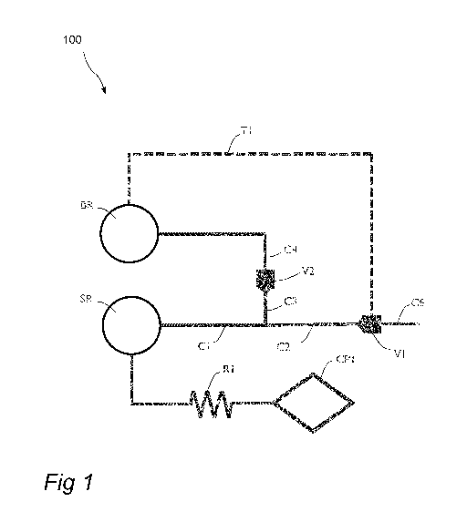
Referring to Fig. 1, an arrangement 100 in a capillary driven fluid
system for metering a predetermined volume of sample fluid will now be
described in detail. The arrangement may typically be a part of a chip with
etched structures, such as channels, cavities etc.
The arrangement 100 comprises a sample reservoir SR arranged to
receive a sample fluid. The sample fluid may be for example blood from a
patient. However, the sample fluid may be any kind of fluid of interest, such
as a chemical compound in liquid form, a powder dispersed in a liquid etc.
The arrangement 100 further comprises a first channel Cl which is in
fluid communication with the sample reservoir SR. The first channel Cl
branches off into a second channel C2 and a third channel C3. The second
channel C2 ends at a first valve V1 and the third channel C3 ends at a
second valve V2, respectively. The second channel C2 and the third channel
C3 together have a predetermined volume. In other words, the arrangement
will be able to meter a volume of sample fluid which is the sum of the volume
of the second channel C2 and the volume of the third channel C3 of the
CA 03060009 2019-10-15
WO 2018/197337 PCT/EP2018/060070
12
sample fluid. This implies that metered volume (i.e. the predetermined
volume) is fixed once the channels C2 and C3 are designed.
The first channel Cl is arranged to draw sample fluid from the sample
reservoir SR by use of capillary forces to fill the second channel C2 and the
third channel C3 with the predetermined volume of sample fluid.
The arrangement 100 further comprises a capillary pump CP1
arranged to empty the sample reservoir SR after the second channel C2 and
the third channel C3 have been filled with sample fluid. Capillary pumps may
be realized in different ways. A simple capillary pump is a microchannel
having a sufficient volume to accommodate the volume of liquid that needs to
be displaced in a specific case. Another simple capillary pump is a cavity,
which may be filled with posts, pillars, packed beads, or some other porous
structure to generate a sufficient capillary force while having a large enough
volume to accommodate the application. Capillary pressure in the capillary
pump may be increased by use of smaller parallel microchannels.
In the embodiment, the first channel Cl is fluidically connected to the
sample reservoir SR so as to draw sample fluid directly from the sample
reservoir. Furthermore, the capillary pump CP1 is fluidically connected to the
sample reservoir SR via a first flow resistor R1. The first flow resistor R1
has
a flow resistance which is selected to control the flow rate from the sample
reservoir SR to the capillary pump CP1 such that the sample reservoir SR is
emptied after the second C2 and third C3 channels have been filled with
sample fluid. In other words, the first flow resistor R1 has been designed so
that the sample reservoir SR is emptied of sample fluid after sufficient time
has been given for the sample fluid to completely fill the metered volume of
the second channel C2 and the third channel C3.
The arrangement 100 further comprises a buffer reservoir BR arranged
to receive a buffer fluid. In this embodiment, the buffer fluid must be added
to
the buffer reservoir after the sample reservoir has been emptied of sample
fluid. The buffer fluid may be for example phosphate buffered saline (PBS)
solution.
The arrangement 100 further comprises a fourth channel C4. The
fourth channel C4 is arranged such that the second valve V2 is fluidically
CA 03060009 2019-10-15
WO 2018/197337
PCT/EP2018/060070
13
connected to the buffer reservoir BR via the fourth channel C4. The fourth
channel C4 is thus arranged to draw buffer fluid from the buffer reservoir BR
by use of capillary forces after the sample reservoir SR has been emptied.
The fourth channel C4 is further arranged to open the second valve V2 as
buffer fluid in the fourth channel C4 reaches the second valve V2. The
opening of the second valve V2 will allow a fluid path to open up. The fluid
path includes the fourth channel C4, the third channel C3 and the second
channel C2. The fluid path is opened up from the buffer reservoir BR to the
first valve V1.
The arrangement 100 further comprises a first control circuit Ti
arranged to open the first valve V1 after the sample reservoir SR has been
emptied. This will allow for a capillary driven flow to arise in the fluid
path,
thereby causing the predetermined volume of sample fluid in the second C2
and third C3 channels to flow out through the first valve V1. The first
control
circuit may be in the form of a first fluidic circuit Ti which fluidically
connects
the first valve Vito the buffer reservoir BR. The first fluidic circuit Ti is
arranged to draw buffer fluid from the buffer reservoir BR and open the first
valve V1 as buffer fluid reaches the first valve V1. The first fluidic circuit
may
be one or more further channels fluidically connecting the buffer reservoir BR
with the first valve V1. If dilution of the metered volume in the second C2
and
the third channel C3 is not desired, the resistance of the first fluidic
circuit
shall be much higher than the resistance of the combination of the channels
C2, C3 and C4.
The timing of the arrangement works as follows. The first valve V1 and
the second valve V2 are opened after the second channel C2 and the third
channel C3 has been filled with sample fluid and after the remaining sample
fluid of the sample reservoir SR has been completely emptied by the capillary
pump CP1. The process of emptying the sample reservoir will, in turn, depend
on the time needed for the entire volume of the sample fluid in the sample
reservoir SR to flow into the capillary pump CP1, a process which will depend
on the flow resistor R1. Hence, it is understood that the arrangement may
require careful design of more than one part of the system such that each of
these parts provide a fluid transport speed relating to the fluid transport
speed
CA 03060009 2019-10-15
WO 2018/197337 PCT/EP2018/060070
14
of the other parts in a way that enables the steps to occur following a
desirable timing sequence. Once the predetermined volume of sample fluid in
the second C2 and third C3 channels has been allowed to flow out through
the first valve V1, they enter a sixth channel C6. The sixth channel C6 may be
fluidically connected to an external system arranged to receive the metered
sample fluid. Such an external system may be for example a measurement
device arranged to determine characteristics of the sample fluid, such as the
concentration of the sample fluid or concentration of substituents in the
sample fluid.
The valves described herein (such as the first valve V1 and the second
valve V2) may generally be of different kinds. However, in the embodiment,
the valves are microfluidic valves, so called capillary trigger valves, which
are
arranged to open up for passage of a fluid entering the valve through a main
input upon the valve being reached by a control fluid entering the valve
through a separate control input.
A method for metering a predetermined volume of sample fluid will now
be further described with reference to Figure 1 and the flow chart of Figure
2.
However, it is to be understood that the method may equally well be
applicable to any other embodiment of the arrangement disclosed herein.
In a first step, S102, sample fluid is added to the sample reservoir SR.
The sample fluid may for example be blood.
In a second step, S104, the first channel C1 is set in fluid
communication with the sample reservoir SR. Upon doing so, the first channel
C1 will draw sample fluid from the sample reservoir SR, by use of capillary
forces, to fill the second channel C2 and the third channel C3, which are
branches of the first channel C1, with a predetermined volume of sample
fluid. At this stage, the first valve V1 and the second valve V2 are closed,
thereby causing the sample fluid to stop once the it reaches the first valve
V1
and the second valve V2, respectively.
It should be noted that, for the arrangement 100, the second step S104
may occur naturally as a result from adding the sample fluid to the sample
reservoir SR in the first step S102. For alternative embodiments, the second
step may have to be actively executed, e.g., by opening a valve or similar.
CA 03060009 2019-10-15
WO 2018/197337
PCT/EP2018/060070
In a third step, S106, the sample reservoir SR is emptied by removing
sample fluid using a capillary pump CP1. The third step S106 may run in
parallel with the second step S104 as illustrated by the dashed lines in
Figure 2. For example, referring to Figure 1, the capillary pump CP1 may, via
5 capillary forces, remove sample fluid from the sample reservoir via flow
resistor R1 at the same time as the second C2 and third channels C3 are
filled with sample fluid via the first channel C1. In that case, the flow
resistance R1 to the capillary pump CP1 should be selected such that the
sample reservoir SR is not emptied too fast, i.e., the flow resistance should
be
10 large enough so that the metered channels C2 and C3 are completely
filled
before the sample reservoir is emptied. In other embodiments, such as when
the setup of Fig. 5 for emptying the sample reservoir SR is used, steps S104
and S106 are rather sequential in that the metered channels C2 and C3 are
filled before the capillary pump CP1 starts to empty the sample reservoir SR.
15 After the sample reservoir SR has been emptied by the capillary pump
CP1 a fourth step S108 is initiated. In the fourth step, S108, the second
valve
V2 is set in fluid communication with a buffer reservoir BR which is filled
with
buffer fluid via a fourth channel C4. Upon doing so, the fourth channel C4
starts to draw buffer fluid from the buffer reservoir BR by use of capillary
forces, and opens the second valve V2 as buffer fluid in the fourth channel C4
reaches the second valve V2. At this stage, a new fluid path of low resistance
is thus opened up in the arrangement from the buffer reservoir BR to the first
valve V1. The new fluid path includes the fourth channel C4, the third channel
C3 and the second channel C2.
It should be noted that, for the arrangement 100, the second valve V2
is in fluid communication with the buffer reservoir BR at all times. Thus, the
fourth step S108 may have to be initiated by adding buffer fluid to the buffer
reservoir BR at a specific time. This will ensure that the second valve V2 is
set in fluid communication with the buffer reservoir BR which is filled with
buffer fluid via a fourth channel C4. For alternative embodiments, the second
step may be actively executed, e.g., by actuating a further valve as will be
described in connection to Figures 3-6. In such a case, buffer fluid may be
present in the buffer reservoir BR at all times.
CA 03060009 2019-10-15
WO 2018/197337 PCT/EP2018/060070
16
In a fifth step, S110, the first valve V1 is opened by a first control circuit
Ti. Upon doing so, a capillary driven flow arises in the newly opened fluid
path C4-C3-C2. At this stage, buffer fluid from the buffer reservoir BR will
replace the sample fluid in the metered channels C3 and C2 as the metered
volume of sample fluid is drawn out by capillary forces into channel C6. In
that
way the predetermined volume of sample fluid in the second channel C2 and
the third channel C3 is caused to flow out through the first valve V1. The
second channel C2 and the third channel C3 are replenished by the buffer
fluid while the predetermined volume of sample fluid is transporter further
downstream of the capillary system.
The control of the timing will allow to control the operation of the
arrangements such that the second valve V2 does not open until after the
sample fluid has reached, and filled, the second channel C2 and the third
channel C3, and the sample reservoir SR has been emptied. Otherwise, one
may arrive at a situation where, in the end, additional sample fluid is drawn
from the sample reservoir SR via the first channel C1 and out through the
first
valve V1. In other words, neither of the valves V1 and V2 should be opened
before the metered channels C2 and C3 are filled and the sample reservoir
SR has been emptied. Alternative timing of the opening of valve V1 relative to
the opening of the valve V2 may be used. However, preferably, the control
circuit is arranged to open the first valve V1 simultaneously with or after
the
second valve V2.
In the Figure 1 embodiment, the opening of the second valve V2 is
controlled by the buffer fluid, and it is for practical reasons preferred to
have
the buffer reservoir BR empty at the start of the metering process. Once it is
established that the sample fluid has successfully filled the second channel
C2 and the third channel C3 and the sample reservoir SR has been emptied
of sample fluid via the capillary pump CP1, the buffer fluid may be
administered to the buffer reservoir BR, whereby buffer fluid may be allowed
to reach the second valve V2 by means of capillary driven flow in the fourth
channel C4.
However, in other embodiments, improved timing control may be
obtained if adding a mean which actively controls when buffer fluid reaches
CA 03060009 2019-10-15
WO 2018/197337 PCT/EP2018/060070
17
the second valve V2. An embodiment comprising such a scheme is shown in
Fig. 3. The arrangement 200 of Fig. 3 differs from the arrangement 100 in that
it further comprises a third valve V3 fluidically connected to the fourth
channel
C4 such that buffer fluid drawn from the buffer reservoir BR passes through
the third valve V3 before entering the fourth channel C4. The arrangement
200 further comprises a second control circuit Ti which is arranged to open
the third valve V3 after the sample reservoir SR has been emptied.
Similarly, as for the first control circuit Ti, the second control circuit in
the arrangement 200 may comprise a second fluidic circuit T2. The second
fluidic circuit T2 fluidically connects the third valve V3 to the buffer
reservoir
BR. The second fluidic circuit T2 is arranged to draw buffer fluid from the
buffer reservoir BR and open the third valve V3 as buffer fluid reaches the
third valve V3. The second fluidic circuit T2 may be one or more further
channels fluidically connecting the buffer reservoir BR with the third valve
V3.
The timing of the opening of the third valve V3 by the second control
circuit T2 will now be discussed. Preferably-, the second valve V2 may not be
opened until after the sample reservoir SR has been emptied. The correct
timing may be achieved by carefully designing the second fluidic circuit T2
such that the time needed for the buffer fluid to reach all the way from the
buffer reservoir BR to the third valve V3 is sufficient to allow for the
second
valve V2 to open after the sample fluid has been emptied from the sample
reservoir SR. The first control circuit Ti may be arranged to open the first
valve V1 simultaneously with or after an opening of the second valve V2. As
previously mentioned, this implies that different parts of the arrangement
must
be designed such that the fluid flow speed in the different parts relate to
each
other in a specific way for the arrangement to work as intended. Specifically,
this may be realized by using different channel lengths, different channel
cross sections etc.
In the embodiments of Fig. 1 and 3, the first control circuit Ti and the
second control circuit T2 were microfluidic channels. The first valve V1 and
the third valve V3 are thus controlled by buffer fluid reaching the first
valve V1
and the third valve V3 respectively, i.e. they are microfluidic, capillary
trigger
valves. Alternatively, the opening of the first valve V1 and the third valve
V3
CA 03060009 2019-10-15
WO 2018/197337
PCT/EP2018/060070
18
may be electrically controlled. In more detail, at least one of the first
control
circuit Ti and the second control circuit T2 may be arranged to deliver an
electrical control signal to at least one of the first valve V1 and the second
valve V2, wherein the at least one of the first valve V1 and the second valve
V2 is arranged to open upon receipt of the electrical signal. For this
purpose,
the arrangement may further comprise a controller, e.g., in the form of a
microcontroller, which is electrically coupled to the first valve V1 and/or
the
third valve V3. This implies that the first valve V1 and the third valve V3
may
be of another type of microfluidic valve. Different electrically-actuated
valve
mechanisms exist, such as those based on electromagnetic or electrostatic
forces, expansion of conductive polymers, etc. The controller is illustrated
as
item 210 in Fig. 3, but could of course be included in any other of the
arrangements 100, 200, 300, 400, 500 shown herein in the same manner.
The microcontroller can either be integrated into the same fluidic chip as the
arrangement 100, 200, 300, 400, 500, or be a seperate silicon chip. Sensors
may also be integrated into the silicon fluidic chip of the arrangement 100,
200, 300, 400, 500 to serve as inputs to the microcontroller, which in turn
actuates the valves V1 and/or V3 in response to the sensor inputs. For
instance, a sensor may sense when there is liqiud in a certain region of a
chip
and the microcontroller can actuate the valve in response to that signal. The
sensors can be either capacitance, impedance, optical, or other.
The arrangement may be fabricated using a variety of different
methods. One possibility is using silicon microfabrication technology. A two-
step deep reactive ion etching process may be used. The use of such a
process may allow forming channels of two different depths for creating
reliable capillary valve structures. The top surface of the channels of the
whole arrangement may either be open or closed with a top cover.
Specifically, in the embodiments shown in Fig. 1 and 3, the sample fluid
and/or the buffer fluid at least partly is in gaseous communication with
surroundings of the arrangement 100, 200 such as to allow gas trapped within
the sample fluid and/or buffer fluid to escape from the arrangement 100, 200.
For example, the top surface may be covered by a gas permeable sheet. The
gas permeable sheet forms a top cover that allows gas but not liquid to
CA 03060009 2019-10-15
WO 2018/197337
PCT/EP2018/060070
19
escape. The contact angle may not be too low so as to cause premature
failure of the capillary valves. The open fluidic or gas permeable sheet
permits gas to escape as the liquid vapor interface proceeds through the
channels without trapping air.
Alternatively, a gas-tight top cover may be used. To allow gas to
escape in such a case, one or more vents may be used instead. Figure 4
shows an arrangement 300 utilizing such a scheme. The arrangement 300
differs from the arrangement 200 in that the gaseous communication with
surroundings occurs through a further valve V5 fluidically connected to the
second valve V2. The further valve V5 allows gas to pass while blocking
liquids. The excess air is ventilated to the surroundings through a vent. Such
a vent could be for example a small nozzle or hole.
The embodiments of the arrangement shown in Fig. 1, 3 and 4 rely on
the capillary pump CP1 fluidically communicating with the sample reservoir
via a separate branch. Fig. 5 shows an arrangement 400 where the capillary
pump CP1 and the first channel Cl rather have a common connection to the
sample reservoir. It should be noted that the arrangement 400 differs from the
arrangement 300 only in the way sample fluid is administered into the first
channel Cl. This alternative way administering fluid into the first channel Cl
may of course also be implemented in the arrangements 100 and 200 of Figs
1 and 3.
The arrangement 400 further comprises a fifth channel C5 of lower
capillary pressure than the first channel Cl, second channel C2, and third
channel C3. The first channel Cl is arranged as a branch to the fifth channel
C5. In use, the first channel Cl is therefore arranged to draw fluid from the
sample reservoir SR via the fifth channel C5. The capillary pump CP1 is
fluidically connected to the sample reservoir SR via a path which includes the
fifth channel C5 and which includes a flow restrictor R' such that the
capillary
pump CP1 is arranged to empty the sample reservoir SR via the fifth channel
C5 after the second channel C2 and the third channel C3 have been filled
with sample fluid. The capillary pressure of the capillary pump CP1 should be
designed to be sufficient to suck the resistor R' and channel C5 dry of liquid
after the sample reservoir SR is emptied. Valve V7 functions as a one-way
CA 03060009 2019-10-15
WO 2018/197337
PCT/EP2018/060070
capillary stop valve to prevent the backflow of liquid from the sample
metering
channels C2 and C3 through channel Cl into channel C5 once valves V1 and
V2 are actuated. The one-way capillary stop valve V7 allows fluid to flow
unimpeded from channel C5 into channel Cl but upon drying of channel C5,
5 capillary forces prevent the fluid from flowing back through channel Cl
into
channel C5.
When in use, the arrangement 400 operates as follows: Sample is
added to the sample reservoir SR and drawn through the flow restrictor R'
into the fifth channel C5. The flow restrictor R' could, e.g., be in the form
of a
10 fluidic channel, the length of which causes a flow resistance. It could
also be
in the form of an orifice to the fifth channel C5, causing the flow to be
restricted. The flow restrictor R' could also be included in the fifth channel
C5
itself. For example, the fifth channel C5 could be designed to be of
considerable length, thereby causing it to serve as a flow restrictor. The
fifth
15 channel C5 typically has a larger channel cross section than the other
channels of the arrangement 400. A larger channel cross section results in a
lower capillary pressure and hence a lower force exerted on the fluid within
the channel. Because of the higher capillary pressure in the first channel C1
compared to the fifth channel C5 and because of the resistance of the flow
20 restrictor R', the capillary flow preferentially fills the first channel
C1 rather
than continuing to fill the fifth channel C5.
After filling the first channel C1, the flow splits into the second channel
C2 and the third channel C3. The channels C2 and C3 are designed to have
a capillary pressure higher than the fifth channel C5 so that after filling
the
first channel C1, the capillary driven flow continues to fill the second
channel
C2 and the third channel C3 until the liquid vapor interface reaches the first
valve V1 and the second valve V2. Once the capillary interface reaches the
first valve V1 and the second valve V2, the flow of sample fluid stops
proceeding in the branch consisting of the first channel C1, the second
channel C2 and the third channel C3. Instead, the flow of sample fluid will
restart in the fifth channel C5 until the fifth channel C5 is filled and the
capillary interface reaches the capillary pump CP1. Meanwhile, the buffer
fluid
is added to the buffer reservoir BR. Capillary forces draw the buffer fluid
into
CA 03060009 2019-10-15
WO 2018/197337 PCT/EP2018/060070
21
the second channel C2. After the second channel C2 is filled, the flow stops
at the third valve V3. The function of the first control circuit Ti and the
second
control circuit T2 are the same as for the arrangement 300. The second
control circuit, which may be a second fluidic circuit T2, is arranged to open
the third valve V3. The buffer fluid then enters the fourth channel C4 and
opens the second valve V2. The buffer fluid continues until it reaches the
further valve V5 at which the flow stops. The first control circuit, which may
be
a first fluidic circuit Ti, is arranged to open the first valve V1. Once the
first
valve V1 is opened, the sample fluid in the metered volume (i.e. the second
channel C2 and the third channel C3) is drawn by capillary forces into the
sixth channel C6 which is arranged for connecting the arrangement 400 to an
external system. The second channel C2 and the third channel C3 are
replenished by the buffer fluid as the sample fluid is transferred through the
first valve V1 into the sixth channel C6.
For some applications, it may be beneficial to dilute the sample fluid.
Such applications may be for example blood cell counting where the undiluted
sample is too dense to count individual blood cells. Dilution may be carried
out after sample metering, but may advantageously be carried out as a sub
step in the metering process. Figure 6 shows an arrangement 500 capable of
both metering and diluting a sample fluid. The arrangement 500 is based
upon the arrangement 300 shown in Fig. 4 and the metering is carried out in
the same way for both embodiments.
In the arrangement 500, the predetermined volume of sample fluid
flowing out through the first valve V1 is received by a sixth channel C6
ending
at a fourth valve V4. The fourth valve V4 is arranged to dilute the
predetermined volume of sample fluid received from the sixth channel C6 with
buffer fluid received from the buffer reservoir BR via a second flow resistor
R2
so as to create a diluted sample fluid. The fourth channel C3 comprises a
third flow resistor R3. With the arrangement, a ratio between a flow rate of
sample fluid received from the sixth channel C6 and a flow rate of the buffer
fluid received from the buffer reservoir BR is at least partly determined by a
resistance of the second flow resistor R2 and a resistance of the third flow
resistor R3. The mix ratio between the sample fluid in the sample reservoir
CA 03060009 2019-10-15
WO 2018/197337 PCT/EP2018/060070
22
and the buffer in the buffer reservoir is thus primarily determined by the
resistance of second flow resistor R2 and the third flow resistor R3 assuming
that the resistance of all other channels is negligible.
The arrangement 500 further comprises a mixer MX1 which is
fluidically connected to an output of the fourth valve V5 and which is
arranged
to mix the diluted sample fluid. In practice, a variety of different mixers
may be
implemented such as a parallel lamination mixer, herringbone mixer, or
serpentine channel. For capillary flow applications, the serpentine channel
may be preferable due to its resilience against trapping air bubbles and
simplicity of the design. The channel width of the serpentine channel mixer
should be small enough to allow fast diffusion while the channel length should
be sufficient to fully mix the fluid streams.
The arrangement 500 further comprises a further capillary pump CP2
in fluid communication with the mixer MX1 through a detection channel C9,
the further capillary pump being arranged to sustain a flow rate of the
diluted
sample fluid through detection channel C9. The mixer MX1 is designed to mix
the sample fluid with the buffer fluid so that the end result is a homogenous
solution. The detection channel C9 is designed to allow measurement of the
quantity of interest, e.g. counting of blood cells. The counting can be
performed optically, electrically, or by other means. The further capillary
pump
CP2 sustains the flow rate for the period of time needed to perform the assay.
The arrangement 500 further comprises of an optional valve V6 with
associated vent. This vent may be needed in cases where the hydraulic
resistance of the mixer MX1 is large (>1016 Pa*s/m3) and air is unable to
easily escape through MX1 and the capillary pump CP2. Note that, in
practice, capillary pumps CP1 and CP2 are typically vented to atmosphere.
However, if the hydraulic resistance of mixer MX1 is small, valve V6 and the
associated vent can be omitted.
It should be understood that, although the fourth valve V4 is arranged
to mix two fluids with each other, the fourth valve V4 may be of the same type
as the valve type used for e.g. the first valve V1. For example, the valve
type
may be a microfluidic valve type, such as a capillary trigger valve type.
CA 03060009 2019-10-15
WO 2018/197337 PCT/EP2018/060070
23
Actually, if using capillary trigger valves, the first valve V1 will also
allow liquid from the main input and the control input to be mixed. The extent
of mixing is controlled by the flow resistance at the two inputs.
Specifically, for
the first valve V1, the control input typically has considerably higher flow
resistance (i.e. the connecting channel is relatively long and/or cross
section
relatively small) relative to the main input. This ensures that mixing between
the buffer fluid and the sample fluid will be negligible. For the fourth valve
V4,
however, the flow resistance in the input channels are similar, thus resulting
in the sample fluid and the buffer fluid both being allowed to pass the valve
together.
The embodiments described herein are not limited to the above
described examples. Various alternatives, modifications, and equivalents may
be used. For example, further valves may be included, further improving the
timing control of the arrangement. Furthermore, alternative valve technologies
may be used. Therefore, this disclosure should not be limited to the specific
form set forth herein. This disclosure is limited only by the appended claims
and other embodiments than those mentioned above are equally possible
within the scope of the claims.