Note: Descriptions are shown in the official language in which they were submitted.
SYSTEM OF DOUBLE CONCENTRIC PIPES
HAVING DIFFERENT ENTHALPY
TECHNICAL FIELD
[001] The present invention relates to a system of double concentric pipes
having
different enthalpy that is an improvement of patent application number
P20170100033 related to a vertical geothermal aero exchanger.
[002] In order to make the present improvement application understandable, so
that it can be easily implemented, an accurate description of a preferred
embodiment will be given in the following paragraphs.
[003] The components referred to in the description may be selected from
various
equivalents without implying departing from the principles of the invention
established in this documentation.
BACKGROUND
[004] As it has been said in the Argentinian application P20170100033, it is
known that the planet's crust has stable areas in which there are a low
caloric
power and unstable areas where the caloric power is high.
[005] Between both areas, there are others of intermediate temperatures that
allow establishing the different types of geothermal energy that corresponds
to
each one of them.
[006] It can be affirmed that the geothermal energy of the unstable areas has
a
temperature ranging between 150 C and 400 C.
- 1 -
CA 3060239 2019-10-24
[007] A high enthalpy field like this is used, for example, to generate steam
and
move a turbine to obtain electricity.
[008] Deepening the segmentation, it can also find areas of medium temperature
(between 90 C and 150 C) and areas of low temperature (between 30 C and
90 C), a range that although it is insufficient to produce electrical energy,
allows
taking advantage of the temperature difference that exists between the near
subsoil and the outside.
[009] The areas where the geothermal energy is lower than 30 C are considered
to be of very low temperature but are suitable for use in climate control
systems.
[0010] To take advantage of the gradient between air and earth temperatures,
heat pumps or heat exchangers are used.
[0011] The climate control system using the proposal disclosed in the
application
P20170100033 presents numerous advantages over the existing devices in the
prior art.
[0012] In effect, the geothermal energy is continuously usable and predictably
throughout the entire year; it is also clean, alternative and renewable, and
considering that as calculated, our planet, as we know it, has a remining life
of
about five billion years. It can be said that we are facing an inexhaustible
source
of energy, that is profitable and efficient.
[0013] The use of geothermal energy does not require fuel deposits, or
batteries,
resulting in a system of high efficiency, low operational cost, and safer.
[0014] Another benefit provided by the described invention is that of causing
a
minimal environmental impact as a result of there being minimal waste
production.
For instance, CO2 emissions are reduced by 95%, compared to conventional
conditioning systems.
- 2 -
CA 3060239 2019-10-24
[0015] The location of the system gets adapted to the needs of the building
without
changing the visual aspect and, since it uses energy areas within the
territory, it
does not use external energy sources and is therefore not subject to
variations in
international prices or prices of foreign exchange.
[0016] The solution provided by the Argentinian application P20170100033
allows
the environment climate within a range of between 15 C and 24 C with external
temperatures of the order of between -5 C and 40 C and, considering that
solutions of this type have been known for more than 5000 years, it can affirm
that
they are extremely reliable.
[0017] The operation concept of geothermal climate control systems, or with
known air-to-ground heat exchangers, is based on the thermal stability that
exists
under the surface of the earth. The depth determines the level of temperature
that
is constant within an area and establishes a range that is practically
independent
of the temperature oscillations that occur on the earth's crust.
[0018] The temperature recorded on the earth's crust for a given area of the
planet
varies between certain parameters that are given by climatic factors and the
position of the earth in its orbit around the sun.
[0019] These temperatures are practically independent of the measurements
under the surface but are closely related to the depth.
[0020] In an established area, the greater the depth at which records are
taken,
the greater is the thermal stability obtained.
[0021] Such records will present variations according to the area of the
planet
where they are obtained but with a tendency to unification as the measurements
approach the core of the planet.
- 3 -
CA 3060239 2019-10-24
[0022] The strip between the surface and a depth of approximately 10 meters
has
variations due to the influence of the external environment, but between 10m
and
20m depth, the incidence of the external environment is practically nil, so
that this
layer is ideal to place the provision disclosed in the Argentinian application
P20170100033.
[0023] It has been calculated that the temperature varies 1 C for every 10
meters
of depth, so the most appropriate depth to install the arrangement of the
Argentinian application P20170100033 is the strip between 10 meters and 20
meters deep, since, attentive to the minimum temperature variation that
registers
below 20 meters, installation at greater depth would be uneconomical.
[0024] It is important to rely on thermal stability, since it favors the
exchange of
heat between the subsoil and any other fluid such as, for example, air.
[0025] For this reason, to achieve a provision as revealed in the application
P20170100033, of the appropriate dimensions, the first thing that corresponds
is
to establish the enthalpy of the place.
[0026] In effect, the depth at which the pipes must be buried must provide the
greatest possible thermal equilibrium, independent of the underground
temperature of the surface to achieve thermal stability that should be between
11 C and 24 C.
[0027] If the exchanger system gets located near the surface of the land, the
movement of lands as well as the cost of the work will be low, but the high
thermal
fluctuation will reduce the efficiency of the climatization.
[0028] On the other hand, the thermal fluctuation will be reduced, achieving
an
optimum result at any time of the year, if the exchanger system is located at
a
depth greater than ten meters, but this implies a greater earth movement and a
higher installation cost.
- 4 -
CA 3060239 2019-10-24
[0029] For this reason, in the present application is an improvement of
Argentinian
application P20170100033, where are provided concentric pipes formed in
materials of different thermal conductivity. The air injected into one of
these pipes
raises its temperature to an appropriate value for the user, while the
remaining
pipe isolates it to maintain the air temperature.
[0030] This will achieve a suitable temperature with a lower energy expense
that
can complement the temperature of the air injected from the heat exchanger
with
the same.
[0031] In the prior art, different types of exchanger circuits are known, and
these
are of the open, closed, or hybrid type.
[0032] The aero-geothermal exchangers include a plurality of tubes located
underground to achieve heat exchange between it and the tubes.
[0033] In the prior art, the tubes are formed in high thermal diffusion
materials to
achieve a better heat exchange.
[0034] The material of the tubes can be selected, allowing to maintain
effectiveness but reducing the diameter or length of the pipes.
[0035] It is then an object of the invention that is proposed to have a
plurality of
concentric double pipes distributed vertically in the ground.
[0036] It is also an object of the invention that the inner pipe is formed in
a material
different from that of the outer pipe.
SUMMARY
[0037] Basically, the system of double concentric pipes having different
enthalpy
of the present application improvement of Argentinian P20170100033 comprises
- 5 -
CA 3060239 2019-10-24
a plurality of double pipes where the internal pipe is made of a material of
high
thermal conductivity and the external pipe is made of a material of low
thermal
conductivity.
BRIEF DESCRIPTION OF THE DRAWINGS
[0038] In order to achieve a better understanding of the object of the present
invention in Figure 1, it shows a view showing a plurality of external tubes
linked
to heads and branches.
[0039] There is also observed an air inlet, an air outlet, a suction pump, an
impeller and joints arranged in two different heights.
[0040] It is observed that both the external tubes and the branches are
arranged
below the surface of the ground.
[0041] Figure 2 shows a sectional view that allows to observe the external and
internal tubes, the drainage pipe, the head, the wall, the nerve, the seals,
the
tubular element, the throat, the means of separation, the means of retention,
widening, and projections.
[0042] Figure 3 shows a partially sectioned view of the derivation where a
double
"T" is represented as well as the external and internal tubes.
DETAILED DESCRIPTION
[0043] In the accompanying Figures, references have been incorporated that
allow individualizing the various parts and components of the invention.
-6 -
CA 3060239 2019-10-24
[0044] In said figures, the same references indicate the same parts or
components.
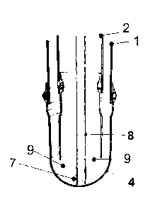
[0045] It is individualized accordingly, with the number (1) an external tube;
with
the number (2) an inner tube; with the number (3) an air inlet; with the
number (4)
a head; with the number (5) a derivation; with the number (6) an air outlet;
with the
number (7) a wall; with the number (8) a tubular element; with the number (9)
a
means of separation; with the number (10) a section and with the number (11)
an
impeller.
[0046] According to what is stated in the Argentinian application number
P20170100033, a plurality of concentric pipes is provided, arranged vertically
and
under the surface of the land, for which an appropriate volume of earth is
extracted
to bury a sufficient quantity of said concentric pipes as for climatizing or
for the
selected environments.
[0047] Each one of said plurality of concentric pipes is formed with an
external
tube (1) and an inner tube (2) of smaller diameter that is disposed inside the
first
one.
[0048] Said external tube (1) is connected to an air inlet (3) fluid that is
taken from
the outside and which runs through said external tube (1) to the lower part of
it
entering the head (4) and from there to the inner tube (2) traveling upwards
towards
a derivation (5) that links it with the air outlet (6), a place where it
returns to the
environment in case of being an open circuit.
[0049] If instead of being an open circuit, it were a closed circuit, the air
would
travel through the inner tube (2) upwards until reaching the branch (5) that
forms
a double "T" and entering one of the branches of said double "T" which is
linked to
the air inlet (3) to restart the cycle.
- 7 -
CA 3060239 2019-10-24
[0050] In the case of being in a mixed circuit, the air that rises through the
inner
tube (2) enters through one of the branches of the double "T" to mix with
fresh air
that enters from the air inlet (3) to the other branch of said double "T".
[0051] Between the internal face of the wall (7) and the cylindrical surface
of the
tubular element (8), separation device (9) is arranged in a number equal to or
greater than two.
[0052] The separation device (9) has the function of keeping constant the
space
between the external (1) and inner (2) tubes, as well as that between the
tubular
element (8) and the head (4), and project from any of them.
[0053] In a preferred embodiment, the separating device (9) includes a fin.
[0054] Connected to the branches (5) are tubular sections (10) on which at
least
one impeller (11) forces the climatized air to the room or the environment.
[0055] When using the concentric pipes, it is sought to separate the air inlet
(3)
from the air outlet (6), and it is also achieved that during the displacement
of the
air there is a thermal exchange between the external tube (1) and the earth.
[0056] In order to favor said exchange, the external tube (1) is formed in a
high
thermal diffusion material.
[0057] During the journey through the inner tube (2), it is sought that the
air
maintains, as much as possible, the temperature reached during its journey
through the external tube (1) so that the material of said inner tube (2)
includes
one of low thermal diffusion.
[0058] Also, in a material with low thermal diffusion, the sections (10) are
formed,
which are tubular bodies connected to the branches (5) and by which at least
one
impeller (11) forces the conditioned air into the room(s).
- 8 -
CA 3060239 2019-10-24
[0059] Said branches (5), as well as said at least one impeller (11), are also
formed in said low thermal diffusion material in order to reduce the thermal
exchange and, consequently, reduce the consumption.
[0060] It is proceeding to the study of different materials, both high and low
thermal diffusion for the preparation of the external (1) and inner (2) tubes,
as well
as in the branches (5), the tubular element (8), the sections (10) and the
impeller
(11).
[0061] The study was oriented towards organic and inorganic materials,
concluding that among the first, the plastics met the appropriate conditions.
[0062] Thus, the high thermal diffusion material is preferably a high-density
polyethylene, also known by its acronym (HDPE), while the material of low
thermal
diffusion would be polyvinyl chloride or PVC.
[0063] In effect, the use of High-Density Polyethylene, from now on HDPE as
high
thermal diffusion material, allows to increase the capacity of thermal
exchange
between the air circulating in the installed pipes, as it has been diffused in
the
Argentinian application P20170100033 and the land and to achieve a higher
temperature recovery in less time.
[0064] It has been found that the diffusing capacity of HDPE is between two
and
three times higher than that of Vinyl Polychloride -PVC in the following- the
inventors have considered that the outer tube (1) must be made of HDPE to take
advantage of its high capacity to exchange temperatures between the air
circulating in said external tube (1) and the surrounding earth. On the other
hand,
the inventors have considered that the inner tube (2), the branches (5), the
tubular
element (8), the sections (10) and the impeller (11) must conform to PVC, thus
achieving that these components maintain the circulating air temperature
reached
during the passage through the external tube (1).
- 9 -
CA 3060239 2019-10-24
[0065] Other materials that can be taken into consideration for shaping tubes
of
low thermal diffusion with plastic pipes, previously coated with a product
selected
from expanded glass, polyethylene foam, elastomeric foam or plastic pipes
covered with vermiculite.
[0066] With this combination, the invention offers the possibility of having a
high
capacity to diffuse temperatures as it occurs in the elements formed in HDPE
or in
the materials that are disclosed in the following and, on the other hand, to
have the
capacity of conserving the temperature as it results in the elements formed in
some
of the low thermal diffusion materials to which we refer.
[0067] The use of elements that can preserve the temperature of the injected
air
affects the thermal recovery power of the system in a steady state, which is
of
great importance to bring the thermal diffusion capacity of the interaction
surface
to a level similar or superior to that of the surrounding land.
[0068] In order to replace the HDPE with PVC, it has been seeking to increase
the thermal diffusion of PVC with the addition of minerals, but although its
thermal
diffusion is increased, it is not enough to equal that of the HDPE.
[0069] The thermal advantages of HDPE add its mechanical and strength
characteristics that are similar to those of sanitary PVC, making it optimal
for use
in external tubes (1).
[0070] To improve the quality of the air injected into the environments, and
taking
into account that it is an organic material, the HDPE is treated with an
antibacterial
material, as is usual in the toilet market. The HDPE with sanitary properties
is
optimal in humid environments, as is the case of the walls of the external (1)
and
inner (2) tubes, as a result of condensation due to temperature differences,
condensation that is accentuated in times of heat.
- 10 -
CA 3060239 2019-10-24
[0071] Each conduit also has an inner tube (2) of PVC, so that this inner tube
(2),
concentric, has insulating characteristics or low thermal diffusion, thereby
preventing heat exchange between air to be used in environments, temperature
stabilized, and that circulates through it and the air that enters through the
air inlet
(3) that is at the outside temperature and that circulates through the
external tube
(1).
[0072] The use of HDPE with an antibacterial load in the external tube (1)
increases the capacity of thermal exchange between the air that circulates
through
it and the earth and the use of PVC in the inner tube (2) gives it insulating
characteristics, which impact the thermal recovery power of the system in a
steady
state.
[0073] This is of fundamental importance to bring the thermal diffusion of the
interaction surface to a level similar or superior to that of the surrounding
earth.
The thermal diffusivity associated with HDPE is higher than that of PVC with
mineral aggregates to increase its diffusivity. The use of HDPE is adequate
due to
its mechanical characteristics and resistance similar to that of sanitary PVC.
[0074] Another advantage of using HDPE to form the outer tube (1) is that its
price
is reasonable and sustainable against the price of alternative materials
including
PVC with mineral aggregates.
[0075] The fact of having a load of antibacterial material, as is commonly
used in
the market of the plastic industry for sanitary applications, gives it optimum
properties for humid environments, such as those resulting from condensation
in
the pipe.
[0076] The use of HDPE with antibacterial agents results in a lower cost than
PVC,
including PVC with mineral aggregate for the improvement of thermal
diffusivity,
reaching the same sanitary quality standards.
-11 -
CA 3060239 2019-10-24
[0077] Materials that can be considered as variants of those disclosed herein
include those that meet the thermal needs and bactericidal power already
described.
[0078] Among the plastic materials that can be used as an alternative, it is
necessary to consider the sanitary polypropylene (PPL), which has thermal
diffusion properties similar to those of the HDPE and since its common use is
water
transport, it usually has a bactericidal load incorporated.
[0079] As an alternative for making the outer tubes (1), inorganic materials
with
high thermal diffusion can also be used, such as, for example, hot galvanized
steel
pipes which are frequently used in water wells. Galvanizing prevents the
formation
of rust for periods exceeding 50 years. Since there is no organic matter in
its
composition, the bactericidal properties of the surface are not so necessary.
[0080] Other alternative materials that can be used for the manufacture of
external
tubes (1) are gastronomic stainless steel and aluminum alloys.
[0081] Even when these alternative materials meet sanitary conditions, their
use
is restricted because their cost is greater than that of plastics.
[0082] In this way, one of the possible sequences of steps that lead to
specifying
the invention and the manner in which it functions has been outlined, and the
documentation is supplemented with the synthesis of the invention contained in
the clauses claiming that are added below.
- 12 -
CA 3060239 2019-10-24