Note: Descriptions are shown in the official language in which they were submitted.
CA 03060531 2019-10-22
WO 2018/085048
PCT/US2017/057273
PLUG-IN ENERGY STORAGE BATTERIES AND NETWORKED PLUG-IN ENERGY
STORAGE BATTERIES
Inventor: Eric Hafner
Cross-Reference to Related Applications
[0001]
This application claims priority to U.S. Provisional Patent Application No.
62/416,152, titled "ENERGY STORAGE BATTERIES" filed November 1, 2016, U.S.
Provisional Patent Application No. 62/435,341, titled "ENERGY STORAGE
BATTERIES"
filed December 16, 2016, and U.S. Provisional Patent Application No.
62/553,642, titled
"ENERGY STORAGE BATTERIES" filed September 1, 2017, which are fully
incorporated
herein by reference for any reason.
FIELD OF THE INVENTION
[0002]
This disclosure relates generally to batteries for charging and discharging.
More
specifically, this disclosure relates to energy storage devices for readily
plugging into wall
outlets and for use as light fixtures.
BACKGROUND OF THE INVENTION
[0003]
Most buildings include an electrical system that provides power for electrical
devices through the distribution of electrical conductors throughout and
ending in outlets for
such things as lighting and convenience receptacles. It is well known in the
industry that the
cost to produce and the price to purchase energy varies throughout the day. It
is desirable to
store this energy when it is less expensive, and to use this stored energy
when it is more
expensive. In this way, the cost of using the energy is reduced.
BRIEF SUMMARY OF THE INVENTION
[0004] The
present disclosure is directed to a distributed and coordinated group of
energy
storage batteries, which store energy when it is less expensive, and discharge
the stored
energy when it is more expensive or required. The present disclosure is also
directed to a
1
CA 03060531 2019-10-22
WO 2018/085048
PCT/US2017/057273
method of coordinating the charge and discharge of the energy of the storage
batteries. These
and other features, aspects and advantages of the present invention will be
best understood
from the following description, when read in conjunction with the accompanying
drawings
and appending claims.
[0005] In an example embodiment, a battery unit comprises a battery unit
housing; and a
battery unit circuit. In this example embodiment, the battery unit housing
contains at least a
portion of the battery unit circuit, and the battery unit circuit further
comprises: a battery cell,
an inverter to control the charging and discharging of the battery cell, a
processor to provide
control signals to the inverter for controlling the charging and discharging
of the battery cell,
and one of: a power plug for coupling to and uncoupling from a power outlet
assembly, and a
luminaire base for coupling to and uncoupling from a luminaire socket in a
light fixture. In
this example embodiment, the battery unit is rated at less than or equal to
2400 Volt-
Amperes.
[0006] In
another example embodiment, a battery unit network comprises: a first battery
unit and a second battery unit. In this example embodiment, the first battery
unit and the
second battery unit each comprises: a battery unit housing, a battery unit
circuit, wherein the
battery unit housing contains at least a portion of the battery unit circuit.
The battery unit
circuit further comprises: a battery cell, an inverter to control the charging
and discharging of
the battery cell, a processor to provide inverter control signals to the
inverter for controlling
the charging and discharging of the battery cell, and a transceiver to provide
processor
signals to the processor, wherein the inverter control signals are at least
partially based on the
processor signals. The battery unit circuit further comprises one of: a power
plug for
coupling to and uncoupling from a power outlet assembly, and a luminaire base
for coupling
to and uncoupling from a luminaire socket in a light fixture. In an example
embodiment, the
first battery unit and the second battery unit are each rated at less than or
equal to 2400 Volt-
Amperes. In an example embodiment, the first battery unit stores a first
amount of energy
and the second battery unit stores a second amount of energy. In this example
embodiment,
the first battery unit wirelessly receives first S control signals, wherein
the control of the
charging or discharging of the first battery unit is based on the first
Scontroi signals. And in
this example embodiment, the second battery unit wirelessly receives second S
control signals,
wherein the control of the charging or discharging of the second battery unit
is based on the
second Scontroi signals.
2
CA 03060531 2019-10-22
WO 2018/085048
PCT/US2017/057273
BRIEF DESCRIPTION OF THE DRAWINGS
[0007] It should be noted that like reference characters are used
throughout the various
views of the Drawings:
[0008] FIGS. 1 and 2 are front and back perspective views, respectively, of
a battery
unit.
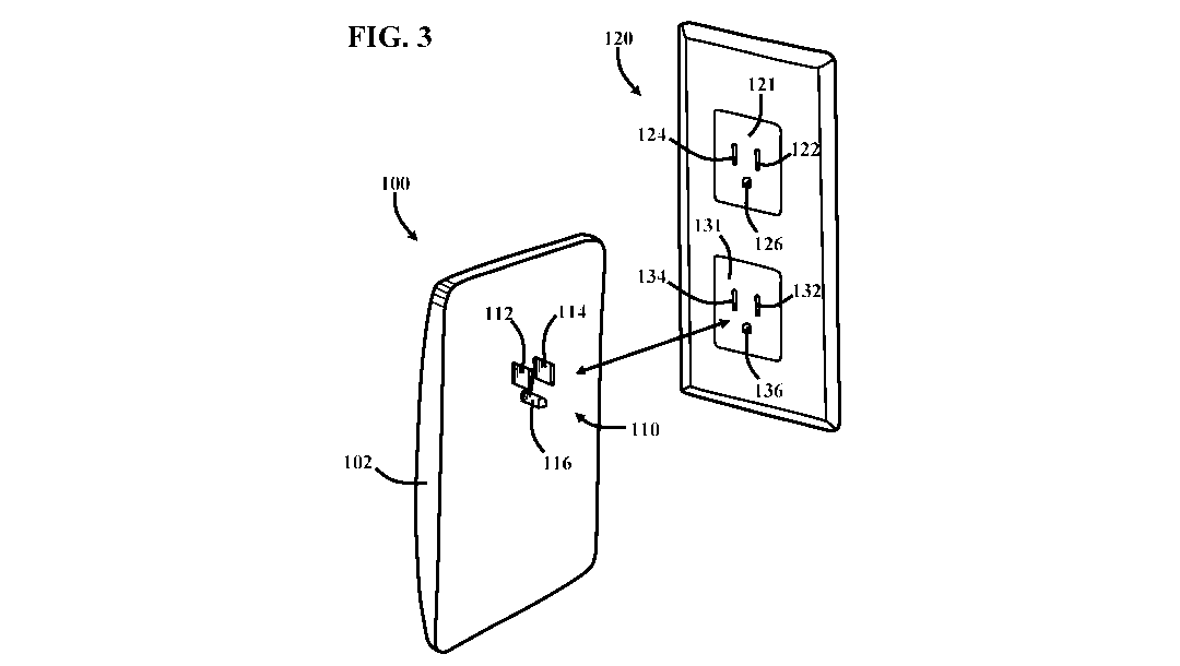
[0009] FIGS. 3 and 4 are perspective views of the battery unit of FIGS. 1
and 2 in
uncoupled and coupled positions with a power outlet assembly.
[0010] FIG. 5 is a block diagram of a first portion of a battery unit
circuit, which is
included with the battery unit of FIGS. 1 and 2.
[0011] FIG. 6 is a block diagram of a second portion of the battery unit
circuit of FIG. S.
[0012] FIG. 7 is a perspective view of another embodiment of a battery
unit.
[0013] FIG. 8 is a perspective view of the battery unit of FIG. 7 and a
frame.
[0014] FIG. 9 is a close-up perspective view of a power outlet assembly
included with
the battery unit of FIG. 7.
[0015] FIG. 10 is a block diagram of a first portion of a battery unit
circuit, which is
included with the battery unit of FIG. 7.
[0016] FIG. 11 is a block diagram of a second portion of the battery unit
circuit of FIG.
10.
[0017] FIGS. 12 and 13 are perspective views of a first embodiment of a
battery unit
network.
[0018] FIG. 14 is a perspective view of a second embodiment of a battery
unit network.
[0019] FIG. 15 is a perspective view of a third embodiment of a battery
unit network.
[0020] FIG. 16 is a side view of a light fixture, which includes a
battery unit circuit.
[0021] FIG. 17 is a side view of a can light fixture, which includes a
battery unit circuit.
[0022] FIG. 18 is a side view of a luminaire, which is included with the
can light fixture
of FIG. 17.
[0023] FIG. 19 is a side view of another embodiment of a can light
fixture, which
includes a battery unit circuit.
[0024] FIG. 20 is a block diagram of a first portion of the battery unit
circuit, which can
be included with the light fixtures of FIGS. 16, 17, 18, and 19.
[0025] FIG. 21 is a block diagram of a second portion of the battery unit
circuit of FIG.
20.
3
CA 03060531 2019-10-22
WO 2018/085048
PCT/US2017/057273
[0026] FIGS. 22 and 23 are perspective views of a fourth embodiment of a
battery unit
network.
[0027] FIG. 24 is a perspective view of a fifth embodiment of a battery
unit network.
[0028] FIG. 25 is a perspective view of a sixth embodiment of a battery
unit network.
DETAILED DESCRIPTION OF THE INVENTION
[0029] While exemplary embodiments are described herein in sufficient
detail to enable
those skilled in the art to practice the invention, it should be understood
that other
embodiments may be realized and that logical material, electrical, and
mechanical changes
may be made without departing from the spirit and scope of the invention.
Thus, the
following detailed description is presented for purposes of illustration only.
[0030] In an example embodiment, a battery unit comprises a battery unit
housing; and a
battery unit circuit. In this example embodiment, the battery unit housing
contains at least a
portion of the battery unit circuit, and the battery unit circuit further
comprises: a battery cell,
an inverter to control the charging and discharging of the battery cell, a
processor to provide
control signals to the inverter for controlling the charging and discharging
of the battery cell,
and one of: a power plug for coupling to and uncoupling from a power outlet
assembly, and a
luminaire base for coupling to and uncoupling from a luminaire socket in a
light fixture. In
this example embodiment, the battery unit is rated at less than or equal to
2400 Volt-
Amperes.
[0031] FIGS. 1 and 2 are front and back perspective views, respectively,
of a battery unit
100. As will be discussed in more detail below with FIG. 5, the battery unit
100 includes a
battery unit circuit. The battery unit circuit controls the operation of the
battery unit 100.
[0032] In this embodiment, the battery unit 100 includes a battery unit
housing 102. The
battery unit housing 102 houses the various components of the battery unit
100. For
example, the battery unit housing 102 houses the battery unit circuit. The
battery unit
housing 102 carries some of the components of the battery unit 100, as will be
discussed in
more detail presently.
[0033] In this embodiment, the battery unit 100 includes a battery unit
power indicator
104, which is carried by the battery unit housing 102. The battery unit power
indicator 104
provides an indication of the amount of power stored by the battery unit 100.
In operation,
the battery unit power indicator 104 moves light in a first direction in
response to the power
stored by the battery unit 100 increasing. Further, in operation, the battery
unit power
4
CA 03060531 2019-10-22
WO 2018/085048
PCT/US2017/057273
indicator 104 moves light in a second direction in response to the power
stored by the battery
unit 100 decreasing. In an example embodiment, the battery unit power
indicator 104
includes one or more lights to provide an indication of the amount of power
storage. The
lights can be of many different types such as light emitting diodes. The
lights can be of many
different colors, such as red, yellow, and/or green. Moreover, any suitable
indicator or
method of indicating the amount of power stored in the battery unit may be
used. In other
example embodiments, no visible indicators of the amount of power stored in
the battery unit
are provided on the battery unit 100.
[0034] In
this embodiment, the battery unit 100 includes a wireless connection indicator
105, which is carried by the battery unit housing 102. The wireless connection
indicator 105
provides an indication of the amount of wireless connection power received by
the battery
unit 100. The wireless connection power corresponds to the strength of a
wireless signal that
flows between the battery unit 100 and another device. The other device can be
of many
different types, as will be discussed in more detail below with FIGS. 12, 13,
14, and 15.
[0035] In operation, the wireless connection indicator 105 moves light in a
third direction
in response to the wireless connection power received by the battery unit 100
increasing.
Further, in operation, the wireless connection indicator 105 moves light in a
fourth direction
in response to the wireless connection power received by the battery unit 100
decreasing.
The wireless connection indicator 105 can include one or more lights to
provide an indication
of the amount of power storage. The lights can be of many different types such
as light
emitting diodes. The lights can be of many different colors, such as red,
yellow, and/or
green. Moreover, any suitable indicator or method of indicating the strength
of the wireless
signal received by the battery unit may be used. In other example embodiments,
no visible
indicators of the strength of the wireless signal are provided on the battery
unit 100.
[0036] In this embodiment, the battery unit 100 includes a charge/discharge
indicator
106, which is carried by the battery unit housing 102. The charge/discharge
indicator 106
provides an indication of the charge state of the battery unit 100. The
charge/discharge
indicator 106 can be of many different types of indicators, such as a light.
The light can be of
many different types such as a light emitting diode. Moreover, any suitable
indicator or
method of indicating the state of the battery unit may be used. In other
example
embodiments, no visible indicators of the state of the battery unit are
provided on the battery
unit 100.
[0037] In
operation, the charge/discharge indicator 106 has a first charge state
indication
in response to the battery unit 100 being charged. The first charge state
indication can be of
5
CA 03060531 2019-10-22
WO 2018/085048
PCT/US2017/057273
many different types of indications, such as a light color indication. The
light color
indication can be of many different colors, such as green.
[0038] In
operation, the charge/discharge indicator 106 has a second charge state
indication in response to the battery unit 100 being discharged. The second
charge state
indication can be of many different types of indications, such as a light
color indication. The
light color indication can be of many different colors, such as red. It should
be noted that
other colors, such as blue and yellow, can also be used to indicate the first
and second charge
states.
[0039] In
an example embodiment, the battery unit 100 includes a power plug 110. The
power plug 110 can be of many different types. In this embodiment, the power
plug 110 is a
three-prong power plug, which includes a positive power prong 112, neutral
power prong
114, and current return prong 116. In this embodiment, the power plug 110 is
rated for 120
volts, so it is a 120 volt power plug. It should be noted that 120 volt power
plugs are
common in the United States. However, the power plug 110 can be rated for
other voltages
and the prongs can be configured for other power outlet configurations
standard in other
countries. For example, the power plug 110 can be rated for other voltages
that are used in
other countries.
[0040]
FIGS. 3 and 4 are perspective views of the battery unit 100 of FIGS. 1 and 2
in
uncoupled and coupled positions with a power outlet assembly 120. The battery
unit 100 can
receive power from the power outlet assembly 120 when it is coupled thereto.
The battery
unit 100 does not receive power from the power outlet assembly 120 when it is
uncoupled
therefrom. Further, the battery unit 100 can provide power to the power outlet
assembly 120
when it is coupled thereto. The battery unit 100 does not provide power to the
power outlet
assembly 120 when it is uncoupled therefrom.
[0041] In this embodiment, the power outlet assembly 120 includes a power
outlet 121.
The power outlet 121 can be of many different types. In this embodiment, the
power outlet
121 is a three-slot power outlet, which includes a positive power slot 122,
neutral power slot
124, and current return slot 126. In this embodiment, the power outlet 121 is
rated for 120
volts, so it is a 120 volt power outlet. It should be noted that 120 volt
power outlets are
common in the United States. However, the power outlet 121 can be rated for
other voltages.
For example, the power outlet 121 can be rated for other voltages that are
used in other
countries.
[0042] In
this embodiment, the power outlet assembly 120 includes a power outlet 131.
The power outlet 131 can be of many different types. In this embodiment, the
power outlet
6
CA 03060531 2019-10-22
WO 2018/085048
PCT/US2017/057273
131 is a three-slot power outlet, which includes a positive power slot 132,
neutral power slot
134, and current return slot 136. In this embodiment, the power outlet 131 is
rated for 120
volts, so it is a 120 volt power outlet. It should be noted that 120 volt
power outlets are
common in the United States. However, the power outlet 131 can be rated for
other voltages.
For example, the power outlet 131 can be rated for other voltages that are
used in other
countries.
[0043] It
should be noted that the power outlet assembly 120 includes two power outlets
in this embodiment for illustrative purposes. In general, the power outlet
assembly 120 can
include one or more power outlets.
[0044] The battery unit 100 is repeatably moveable between the uncoupled
and coupled
positions with the power outlet assembly 120. The battery unit 100 can be
coupled to the
power outlet assembly 120 in many different ways. For example, the battery
unit 100 can be
coupled to the power outlet 121 in response to coupling the power plug 110
thereto. The
power plug 110 is coupled to the power outlet 121 in response to moving the
positive power
prong 112 into the positive power slot 122, the neutral power prong 114 into
the neutral
power slot 124, and the current return prong 116 into the current return slot
126. This is also
referred to as plugging in the power plug 110, or the power plug 110 being
plugged into the
power outlet 121.
[0045] The
battery unit 100 can receive power from the power outlet 121 when the power
plug 110 is coupled thereto. The battery unit 100 does not receive power from
the power
outlet 121 when the power plug 110 is uncoupled therefrom. Further, the
battery unit 100
can provide power to the power outlet 121 when the power plug 110 is coupled
thereto. The
battery unit 100 does not provide power to the power outlet 121 when the power
plug 110 is
uncoupled therefrom.
[0046] In FIGS. 3 and 4, however, the battery unit 100 is coupled to the
power outlet
131 in response to coupling the power plug 110 thereto. The power plug 110 is
coupled to
the power outlet 131 in response to moving the positive power prong 112 into
the positive
power slot 132, the neutral power prong 114 into the neutral power slot 134,
and the current
return prong 116 into the current return slot 136.
[0047] The battery unit 100 can receive power from the power outlet 131
when the power
plug 110 is coupled thereto. The battery unit 100 does not receive power from
the power
outlet 131 when the power plug 110 is uncoupled therefrom. Further, the
battery unit 100
can provide power to the power outlet 131 when the power plug 110 is coupled
thereto. The
battery unit 100 does not provide power to the power outlet 131 when the power
plug 110 is
7
CA 03060531 2019-10-22
WO 2018/085048
PCT/US2017/057273
uncoupled therefrom. Moreover, the battery unit 100, in an example embodiment,
can be
coupled to more than one power outlet (e.g., 121 and 131) at the same time
through use of
corresponding power plugs.
[0048] In
an example embodiment, the battery unit power indicator 104 provides an
indication of the amount of power stored by the battery unit 100. As mentioned
above, the
battery unit power indicator 104 moves light in the first direction in
response to the power
stored by the battery unit 100 increasing. In this embodiment, the battery
unit power
indicator 104 moves light in the first direction in response to the power
flowing from the
power outlet 131 to the battery unit 100 through the power plug 110. In this
way, the power
stored by the battery unit 100 increases.
[0049] As
mentioned above, the battery unit power indicator 104 moves light in the
second direction in response to the power stored by the battery unit 100
decreasing. In this
embodiment, the battery unit power indicator 104 moves light in the second
direction in
response to the power flowing from the battery unit 100 to the power outlet
131 through the
power plug 110. In this way, the power stored by the battery unit 100
decreases.
[0050] As
mentioned above, the charge/discharge indicator 106 provides an indication of
the charge state of the battery unit 100. In operation, the charge/discharge
indicator 106 has
the first charge state indication in response to the power plug 110 being
coupled to the power
outlet 131. Further, in operation, the charge/discharge indicator 106 has the
second charge
state indication in response to the power plug 110 being uncoupled from the
power outlet
131.
[0051] In
this embodiment, the wireless connection indicator 105 provides an indication
of the amount of wireless connection power received by the battery unit 100.
The wireless
connection indicator 105 moves light in the third direction in response to the
wireless
connection power received by the battery unit 100 increasing. The wireless
connection
indicator 105 moves light in the fourth direction in response to the wireless
connection power
received by the battery unit 100 decreasing. As mentioned above, the wireless
connection
power corresponds to the strength of a wireless signal that flows between the
battery unit 100
and another device. The other device can be of many different types, as will
be discussed in
more detail below with FIGS. 12, 13, 14, and 15.
[0052]
FIG. 5 is a block diagram of a first portion of a battery unit circuit 101,
which is
included with the battery unit 100 of FIGS. 1 and 2, and FIG. 6 is a block
diagram of a
second portion of the battery unit circuit 101 of FIG. S. It should be noted
that the battery
8
CA 03060531 2019-10-22
WO 2018/085048
PCT/US2017/057273
unit circuit 101 allows energy to be distributed, in a controlled manner, to
other electrical
devices through the electrical distribution system.
[0053] In
this embodiment, the battery unit circuit 101 includes the power plug 110,
which is described above. The power plug 110 is carried by the battery unit
housing 102, as
shown in FIGS. 2 and 3. As discussed in more detail above, the power plug 110
is
repeatably moveable between coupled and uncoupled positions with the power
outlet
assembly 120. In the coupled condition, a power in signal SPowerIn can be
received by the
power plug 110 from the power outlet assembly 120. Further, in the coupled
condition, a
power out signal SPowerOut can be received by the power outlet assembly 120
from the power
plug 110. It should be noted that the power in signal SPowerIn is a portion of
a power signal
SPower that is provided to the power outlet assembly 120 and the power out
signal SPowerOut is
another portion of the power signal SPower= The power signal Spower can be
provided to the
power outlet assembly 120 in many different ways, such as from a service panel
(not shown).
The service panel is connected to the power outlet assembly 120 through an
electrical
distribution system. It should be noted that, in this embodiment, the power in
SPowerIn, power
out SPowerOut, and power Spo, signals are alternating current power signals.
[0054] The
battery unit circuit 101 includes an inverter 107, which is coupled to the
power plug 110. The inverter 107 can be of many different types. In this
embodiment, the
inverter 107 converts power signals between alternating current and direct
current power
signals. In this embodiment, the inverter 107 receives the power in signal
SPowerIn from the
power plug 110, and provides a battery in signal SBattelyin in response. The
battery in signal
SBarreiyio is a direct current power signal that corresponds to the
alternating current power in
signal SPowerIn= Further, the inverter 107 receives a battery out signal
SBatteiyout, and provides
the power out signal SPowerOut in response. The power out signal SPowerOut is
an alternating
current power signal that corresponds to the direct current battery out signal
SBatteiyour.
[0055] The
battery unit circuit 101 includes a battery cell 108 coupled to the inverter
107.
The battery cell 108 can be of many different types. In this embodiment, the
battery cell 108
is a lithium-ion battery cell. The battery cell 108 provides the battery out
signal SBatteiyour to
the inverter 107. Further, the battery cell 108 receives the battery in signal
SBatteiyIn from the
inverter 107.
[0056] In
this embodiment, the battery unit circuit 101 includes the battery unit power
indicator 104, which is operatively coupled to the battery cell 108. The
battery unit power
indicator 104 is shown in FIGS. 1 and 4. In operation, the battery unit power
indicator 104
moves light in the first direction in response to receiving the battery in
signal SBarteryio.
9
CA 03060531 2019-10-22
WO 2018/085048
PCT/US2017/057273
Further, in operation, the battery unit power indicator 104 moves light in the
second direction
in response to providing the battery out signal SBatteiyout.
[0057] The
battery unit circuit 101 includes a transceiver 109 coupled to the battery
cell
108. The transceiver 109 can be of many different types, such as a Wi-Fi radio
or other mesh
network transceiver that allows communication and control wirelessly. The
transceiver 109
may communicate, for example, with a wireless router in the building. The
transceiver 109 is
powered in response to receiving a battery signal SBattery from the battery
cell 108, wherein
the battery signal SBattery is a direct current power signal. It should be
noted that the battery
signal SBattery can be used to power other components of the battery unit
circuit 101, if
desired.
[0058] In
this embodiment, the battery unit circuit 101 includes the wireless connection
indicator 105, which is operatively coupled to the transceiver 109. The
wireless connection
indicator 105 is shown in FIGS. 1 and 4. As mentioned above, the wireless
connection
indicator 105 provides an indication of the amount of wireless connection
power received by
the battery unit 100. In particular, the wireless connection indicator 105
provides an
indication of the amount of wireless connection power received by the
transceiver 109. The
wireless connection power corresponds to the strength of a wireless signal
that flows between
the battery unit 100 and another device. In particular, the wireless
connection power
corresponds to the strength of a wireless signal that flows between the
transceiver 109 and
another device. The other device can be of many different types, as will be
discussed in more
detail below with FIGS. 12, 13, 14, and 15.
[0059] In
operation, the wireless connection indicator 105 moves light in the third
direction in response to the wireless connection power received by the
transceiver 109
increasing. Further, in operation, the wireless connection indicator 105 moves
light in the
fourth direction in response to the wireless connection power received by the
transceiver 109
decreasing. The wireless connection power can correspond to the power of many
different
types of wireless signals. In this embodiment, the wireless connection power
corresponds to
the power of a control signal Sconimi and/or data signal Spaia. In other
embodiments, such as
those discussed with FIGS. 12, 13, 14, and 15 below, the wireless connection
power
corresponds to one or more wireless signals Si, S2, and S3.
[0060] As
shown in FIG. 6, the control signal Sconiroi and data signal Spata flow
between
the transceiver 109 and intern& 140. It should be noted that the intern& 140
typically
includes one or more computer networks. The computer network can be of many
different
types, such as a wide area network (WAN) and local area network (LAN).
CA 03060531 2019-10-22
WO 2018/085048
PCT/US2017/057273
[0061] In
this embodiment, the intern& 140 is in communication with a database 142,
which is used for data logging, billing, and prediction of future charge and
discharge patterns
of the user based on past consumption locally or remotely. The database 142
can be accessed
remotely via a web portal via computer 144. In an example embodiment, access
to the
database 142 and communication via the interne 140 is intermittent and on
demand.
[0062] In
this embodiment, the database 142 is in communication with a computer 144.
The computer 144 can be of many different types, such as a server, which
operates a web-
based portal or web-based interface. The computer 144 can also be a mobile
device, such as
a smart phone and tablet. Examples of smart phones include the IPHONE and
ANDROID
devices, and an example of a tablet is an IPAD. In an example embodiment, not
shown,
computer 144 is in direct communication with intern& 140.
[0063]
FIG. 7 is a perspective view of another embodiment of a battery unit 150. As
will
be discussed in more detail below with FIG. 10, the battery unit 150 includes
a battery unit
circuit. The battery unit circuit controls the operation of the battery unit
150.
[0064] In this embodiment, the battery unit 150 includes a battery unit
housing 152. The
battery unit housing 152 houses the various components of the battery unit
150. For
example, the battery unit housing 152 houses the battery unit circuit. The
battery unit
housing 152 carries some of the components of the battery unit 150, as will be
discussed in
more detail below.
[0065] In this embodiment, the battery unit 150 includes a power outlet
assembly 160,
which is carried by the battery unit housing 152. The power outlet assembly
160 will be
discussed in more detail with FIG. 9.
[0066] In
this embodiment, the battery unit 150 includes a battery unit stand 154, which
is coupled to the battery unit housing 152. The battery unit stand 154 can be
of many
different types. In this embodiment, the battery unit stand 154 includes a
battery unit
platform 155, which is spaced from the battery unit housing 152 by battery
unit legs 156 and
157. The battery unit stand 154 allows the battery unit 150 to be positioned
at a desired
location, as will be discussed in more detail presently. The battery unit
stand 154 also allows
the battery unit housing 152 to be held at a desired position so that
insulation can be
positioned around it. Further, the battery unit stand 154 allows the power
outlet assembly
160 to be positioned at a desired location, such as a desired height above a
floor.
[0067]
FIG. 8 is a perspective view of the battery unit 150 of FIG. 7 and a frame
180.
The frame 180 can be of many different types. In this embodiment, the frame
180
corresponds to the framing of a wall, which generally includes one or more
beams. In this
11
CA 03060531 2019-10-22
WO 2018/085048
PCT/US2017/057273
embodiment, the frame 180 includes a lower cross beam 181, wherein the battery
unit stand
154 is carried by the lower cross beam 181. The frame 180 includes upright
beams 182 and
183, wherein the battery unit 150 extends therebetween. The frame 180 can
include other
beams, such as upper cross beams 184 and 185, wherein upper cross beams 184
and 185
extend away from upright beams 182 and 183, respectively.
[0068] It
should be noted that a wall member, such as drywall, is typically carried by
the
frame 180. In one particular embodiment, first and second wall members are
positioned on
opposed sides of the frame 180 so that the battery unit 150 is positioned
therebetween. In
this way, the battery unit 150 can be positioned relative to a wall. In some
embodiments, the
battery unit 150 is positioned inside of the wall. The battery unit housing
152 can be
positioned between opposed wall members, and the power outlet assembly 160 can
extend
through one of the wall members, as will be discussed in more detail
presently.
[0069]
FIG. 9 is a close-up perspective view of the power outlet assembly 160
included
with the battery unit 150 of FIGS. 7 and 8. As mentioned above, the power
outlet assembly
160 is carried by the battery unit housing 152. In this embodiment, the power
outlet
assembly 160 extends proximate to a wall member 187, wherein the wall member
187 is
carried by the frame 180 (FIG. 8).
[0070] The
power outlet assembly 160 can be of many different types. In this
embodiment, the power outlet assembly 160 includes a power outlet 161. The
power outlet
161 can be of many different types. In this embodiment, the power outlet 161
is a three-slot
power outlet, which includes a positive power slot 162, neutral power slot
164, and current
return slot 166. In this embodiment, the power outlet 161 is rated for 120
volts, so it is a 120
volt power outlet. As mentioned above, 120 volt power outlets are common in
the United
States. However, the power outlet 161 can be rated for other voltages. For
example, the
power outlet 161 can be rated for other voltages that are used in other
countries.
[0071] In
this embodiment, the power outlet assembly 160 includes a power outlet 171.
The power outlet 171 can be of many different types. In this embodiment, the
power outlet
171 is a three-slot power outlet, which includes a positive power slot 172,
neutral power slot
174, and current return slot 176. In this embodiment, the power outlet 171 is
rated for 120
volts, so it is a 120 volt power outlet. As mentioned above, 120 volt power
outlets are
common in the United States. However, the power outlet 171 can be rated for
other voltages.
For example, the power outlet 171 can be rated for other voltages that are
used in other
countries.
12
CA 03060531 2019-10-22
WO 2018/085048
PCT/US2017/057273
[0072] It
should be noted that the power outlet assembly 160 includes two power outlets
in this embodiment for illustrative purposes. In general, the power outlet
assembly 160 can
include one or more power outlets.
[0073] In
this embodiment, the power outlet assembly 160 includes a battery unit power
indicator 104. As mentioned above, the battery unit power indicator 104
provides an
indication of the amount of power stored by the battery unit 150. In
operation, the battery
unit power indicator 104 moves in the first direction in response to the power
stored by the
battery unit 150 increasing. Further, in operation, the battery unit power
indicator 104 moves
in the second direction in response to the power stored by the battery unit
150 decreasing.
More information regarding the battery unit power indicator 104 is provided
above.
[0074] In
this embodiment, the power outlet assembly 160 includes the wireless
connection indicator 105. The wireless connection indicator 105 provides an
indication of
the amount of wireless connection power received by the battery unit 150. The
wireless
connection power corresponds to the strength of a wireless signal that flows
between the
battery unit 150 and another device. The other device can be of many different
types, as will
be discussed in more detail below with FIGS. 10, 11, 12, and 13.
[0075] In
operation, the wireless connection indicator 105 moves in the third direction
in
response to the wireless connection power received by the battery unit 150
increasing.
Further, in operation, the wireless connection indicator 105 moves in the
fourth direction in
response to the wireless connection power received by the battery unit 150
decreasing. The
wireless connection indicator 105 can include one or more lights to provide an
indication of
the amount of power storage. The lights can be of many different types such as
light emitting
diodes. The lights can be of many different colors, such as red, yellow,
and/or green.
[0076] In
this embodiment, the power outlet assembly 160 includes the charge/discharge
indicator 106. The charge/discharge indicator 106 provides an indication of
the charge state
of the battery unit 150. As mentioned above, the charge/discharge indicator
106 can be of
many different types of indicators, such as a light. The light can be of many
different types
such as a light emitting diode.
[0077] In
operation, the charge/discharge indicator 106 has the first charge state
indication in response to the battery unit 100 being charged. As mentioned
above, the first
charge state indication can be of many different types of indications, such as
a light color
indication. The light color indication can be of many different colors, such
as green.
[0078] In
operation, the charge/discharge indicator 106 has the second charge state
indication in response to the battery unit 100 being discharged. As mentioned
above, the
13
CA 03060531 2019-10-22
WO 2018/085048
PCT/US2017/057273
second charge state indication can be of many different types of indications,
such as a light
color indication. The light color indication can be of many different colors,
such as red. It
should be noted that other colors, such as blue and yellow, can also be used
to indicate the
first and second charge states.
[0079] FIG. 10 is a block diagram of the battery unit circuit 151, which is
included with
the battery unit 150 of FIGS. 7, 8 and 9, and FIG. 11 is a block diagram of a
second portion
of the battery unit circuit 151 of FIGS. 10. It should be noted that the
battery unit circuit 151
allows energy to be distributed, in a controlled manner, to other electrical
devices through the
electrical distribution system.
[0080] In this embodiment, the battery unit circuit 151 includes the power
outlet
assembly 160, which is described above. The power outlet assembly 160 is
carried by the
battery unit housing 151, as shown in FIGS. 7, 8, and 9. The power outlet
assembly 160
receives the power signal SPower= The power signal SPower can be provided to
the power outlet
assembly 160 in many different ways, such as from the service panel (not
shown). The
.. service panel is connected to the power outlet assembly 160 through an
electrical distribution
system. An example electrical distribution system is a power grid, a micro-
grid, and the like.
[0081] In
this embodiment, the battery unit circuit 151 includes the inverter 107, which
is
coupled to the power outlet assembly 160. As mentioned above, the inverter 107
can be of
many different types. In this embodiment, the inverter 107 converts power
signals between
alternating current and direct current power signals. In this embodiment, the
inverter 107
receives the power in signal SPowerIn from the power outlet assembly 160, and
provides the
battery in signal SBatteiyin in response. The battery in signal SBatteryIn is
a direct current power
signal that corresponds to the alternating current power in signal SPowerIn=
Further, the
inverter receives the battery out signal SBatteiyOut, and provides the power
out signal SPowerOut
in response. The power out signal SPowerOut is an alternating current power
signal that
corresponds to the direct current battery out signal SBatteiyout.
[0082] In
this embodiment, the battery unit circuit 151 includes the battery cell 108
coupled to the inverter 107. As mentioned above, the battery cell 108 can be
of many
different types. In this embodiment, the battery cell 108 is a lithium-ion
battery cell. The
battery cell 108 provides the battery out signal SBatteiyout to the inverter
107. Further, the
battery cell 108 receives the battery in signal SBatteryIn from the inverter
107. It should be
noted that the power in signal Spowean is a portion of the power signal SPower
that is provided
to the power outlet assembly 160 and that the power out signal SPowerOut is
another portion of
the power signal SPower that is sent from the power outlet assembly 160 to the
electrical
14
CA 03060531 2019-10-22
WO 2018/085048
PCT/US2017/057273
system. It also should be noted that, in this embodiment, the power in
SPowerIn, power out
Spoweront, and power Spo, signals are alternating current power signals.
[0083] In
this embodiment, the power outlet assembly 160 includes the battery unit
power indicator 104, which is operatively coupled to the battery cell 108. The
battery unit
power indicator 104 is shown in FIG. 9. In operation, the battery unit power
indicator 104
moves light in the first direction in response to receiving the battery in
signal SBatteryin.
Further, in operation, the battery unit power indicator 104 moves light in the
second direction
in response to providing the battery out signal SBattelyout.
[0084] The
battery unit circuit 101 includes a transceiver 109 coupled to the battery
cell
108. The transceiver 109 can be of many different types, such as a Wi-Fi radio
or other mesh
network transceiver that allows communication and control wirelessly. The
transceiver 109
is powered in response to receiving the battery signal SBarrely from the
battery cell 108,
wherein the battery signal SBarrely is a direct current power signal. As
mentioned above, the
battery signal SBattery can be used to power other components of the battery
unit circuit 101, if
desired.
[0085] In
this embodiment, the power outlet assembly 160 includes the wireless
connection indicator 105, which is operatively coupled to the transceiver 109.
The wireless
connection indicator 105 is shown in FIG. 9. As mentioned above, the wireless
connection
indicator 105 provides an indication of the amount of wireless connection
power received by
the battery unit 100. In particular, the wireless connection indicator 105
provides an
indication of the amount of wireless connection power received by the
transceiver 109. The
wireless connection power corresponds to the strength of a wireless signal
that flows between
the battery unit 100 and another device. In particular, the wireless
connection power
corresponds to the strength of a wireless signal that flows between the
transceiver 109 and
another device. The other device can be of many different types, as will be
discussed in more
detail below with FIGS. 12, 13, 14, and 15.
[0086] In
operation, the wireless connection indicator 105 moves light in the third
direction in response to the wireless connection power received by the
transceiver 109
increasing. Further, in operation, the wireless connection indicator 105 moves
light in the
fourth direction in response to the wireless connection power received by the
transceiver 109
decreasing. The wireless connection power can correspond to the power of many
different
types of wireless signals. In this embodiment, the wireless connection power
corresponds to
the power of the control signal Scontrol and/or data signal SData. In other
embodiments, such as
CA 03060531 2019-10-22
WO 2018/085048
PCT/US2017/057273
those discussed with FIGS. 12, 13, 14, and 15 below, the wireless connection
power
corresponds to one or more wireless signals Si, S2, and S3.
[0087] As
shown in FIG. 11, the control signal Sconiroi and data signal Spata flow
between
the transceiver 109 and intern& 140. It should be noted that the intern& 140
typically
includes one or more computer networks. The computer network can be of many
different
types, such as a wide area network (WAN) and local area network (LAN).
[0088] In
this embodiment, the intern& 140 is in communication with a database 142,
which is used for data logging, billing, and prediction of future charge and
discharge patterns
of the user based on past consumption locally or remotely. The database 142
can be accessed
remotely via a web portal via computer 144. In an example embodiment, the
communication
with the database 142 and communication via the intern& 140 will be
intermittent and on
demand.
[0089] In
this embodiment, the database 142 is in communication with a computer 144.
The computer 144 can be of many different types, such as a server, which
operates a web-
based portal or web-based interface. The computer 144 can also be a mobile
device, such as
a smart phone and tablet. Examples of smart phones include the IPHONE and
ANDROID
devices, and an example of a tablet is an IPAD. In an example embodiment, not
shown, the
computer 144 is in direct communication with the intern& 140.
[0090]
FIGS. 12 and 13 are perspective views of a first embodiment of a battery unit
network, denoted as battery unit network 190. In this embodiment, a power
outlet assembly
120a extends through the wall member 187, wherein the power outlet assembly
120a is the
same as the power outlet assembly 120. The battery unit network 190 includes a
battery unit
100a, which is repeatably moveable between uncoupled (FIG. 12) and coupled
(FIG. 13)
positions with the power outlet assembly 120a. It should be noted that the
battery unit 100a
is the same as the battery unit 100, and includes the battery unit circuit 101
(FIGS. 5 and 6).
More information regarding moving the battery unit 100a between coupled and
uncoupled
conditions with the power outlet assembly 120a is provided in more detail
above with FIGS.
3 and 4.
[0091] In
this embodiment, a power outlet assembly 120b extends through the wall
member 188, wherein the power outlet assembly 120b is the same as the power
outlet
assembly 120. The battery unit network 190 includes a battery unit 100b, which
is repeatably
moveable between uncoupled (FIG. 12) and coupled (FIG. 13) positions with the
power
outlet assembly 120b. It should be noted that the battery unit 100b is the
same as the battery
unit 100. More information regarding moving the battery unit 100b between
coupled and
16
CA 03060531 2019-10-22
WO 2018/085048
PCT/US2017/057273
uncoupled conditions with the power outlet assembly 120b is provided in more
detail above
with FIGS. 3 and 4. It should be noted that wall members 187 and 188 are
typically carried
by a frame, such as the frame 180 of FIG. 8.
[0092] In
this embodiment, the battery units 100a and 100b establish communication
with each other so that a wireless signal Si can flow therebetween. The
wireless signal Si is
used to coordinate a discharge on the electrical distribution system to
aggregate the available
capacity of the distributed energy storage system. For example, the wireless
signal Si can
coordinate the discharge on the electrical distribution system between the
battery units 100a
and 100b to aggregate the available capacity between them.
[0093] The battery unit 100a can establish communication with a first
remote device so
that a wireless signal S2 can flow therebetween. The wireless signal S2 is
used to coordinate
charge and discharge sequences on the electrical distribution system to
aggregate the
available capacity of the distributed energy storage system. For example, the
wireless signal
S2 can coordinate the discharge on the electrical distribution system between
the battery unit
100a and the first remote device to aggregate the available capacity between
them.
[0094] The
battery unit 100b can establish communication with a second remote device
so that a wireless signal S3 can flow therebetween. The wireless signal S3 is
used to
coordinate charge and discharge sequences on the electrical distribution
system to aggregate
the available capacity of the distributed energy storage system. For example,
the wireless
signal S3 can coordinate the discharge on the electrical distribution system
between the
battery unit 100b and the third remote device to aggregate the available
capacity between
them.
[0095] It
should be noted that the first and second remote devices can be of many
different types, such as a computer, smart phone, and/or tablet. The first and
second remote
devices can also be a server, which operates a web-based portal or web-based
interface.
[0096]
FIG. 14 is a perspective view of a second embodiment of a battery unit
network,
denoted as battery unit network 191. In this embodiment, the battery unit
network 191
includes a battery unit 150a, wherein the battery unit 150a includes a power
outlet assembly
160a. It should be noted that the battery unit 150a is the same as the battery
unit 150 (FIGS.
7, 8, and 9), and includes the battery unit circuit 151 (FIGS. 10 and 11).
Further, the power
outlet assembly 160a corresponds to the power outlet assembly 160 (FIG. 9).
[0097] In
this embodiment, the battery unit 150a extends through the wall member 187,
wherein the wall member 187 is carried by the frame 180 (FIG. 8). Further, the
power outlet
assembly 160a extends through the wall member 187 (FIG. 9).
17
CA 03060531 2019-10-22
WO 2018/085048
PCT/US2017/057273
[0098] The
battery unit network 191 includes the battery unit 100b, which is repeatably
moveable between uncoupled (FIG. 12) and coupled (FIG. 13) positions with the
power
outlet assembly 120b. As mentioned above, the battery unit 100b is the same as
the battery
unit 100.
[0099] In this embodiment, the battery units 150a and 100b establish
communication
with each other so that the wireless signal Si can flow therebetween. As
mentioned above,
the wireless signal Si is used to coordinate a discharge on the electrical
distribution system to
aggregate the available capacity of the distributed energy storage system. For
example, the
wireless signal Si can coordinate the discharge on the electrical distribution
system between
.. the battery units 150a and 100b to aggregate the available capacity between
them. Although
discussed herein in various examples as 'coordinating the discharge', it
should be understood
that the wireless signals may also be used to coordinate the charging of
multiple devices
connected to the electrical distribution system.
[00100] The battery unit 150a can establish communication with the first
remote device so
that the wireless signal S2 can flow therebetween. As mentioned above, the
wireless signal
S2 is used to coordinate charge and discharge sequences on the electrical
distribution system
to aggregate the available capacity of the distributed energy storage system.
For example, the
wireless signal S2 can coordinate the discharge on the electrical distribution
system between
the battery unit 150a and the first remote device to aggregate the available
capacity between
them.
[00101] The battery unit 100b can establish communication with the second
remote device
so that a wireless signal S3 can flow therebetween. As mentioned above, the
wireless signal
S3 is used to coordinate charge and discharge sequences on the electrical
distribution system
to aggregate the available capacity of the distributed energy storage system.
For example, the
wireless signal S3 can coordinate the discharge on the electrical distribution
system between
the battery unit 100b and the third remote device to aggregate the available
capacity between
them.
[00102] FIG. 15 is a perspective view of a third embodiment of a battery unit
network,
denoted as battery unit network 192. In this embodiment, the battery unit
network 192
includes the battery unit 150a, wherein the battery unit 150a includes a power
outlet
assembly 160a. As mentioned above, the battery unit 150a is the same as the
battery unit 150
(FIGS. 7,8, and 9), and includes the battery unit circuit 151 (FIGS. 10 and
11). Further, the
power outlet assembly 160a corresponds to the power outlet assembly 160 (FIG.
9).
18
CA 03060531 2019-10-22
WO 2018/085048
PCT/US2017/057273
[00103] As mentioned above, the battery unit 150a extends through the wall
member 187,
wherein the wall member 187 is carried by the frame 180 (FIG. 8). Further, the
power outlet
assembly 160a extends through the wall member 187 (FIG. 9).
[00104] The battery unit network 192 includes a battery unit 150b, wherein the
battery unit
150b includes a power outlet assembly 160b. In this embodiment, the battery
unit 150b is the
same as the battery unit 150 (FIGS. 7, 8, and 9), and includes the battery
unit circuit 151
(FIGS. 10 and 11). Further, the power outlet assembly 160b corresponds to the
power outlet
assembly 160 (FIG. 9).
[00105] As mentioned above, the battery unit 150b extends through the wall
member 188,
wherein the wall member 188 is carried by the frame 180 (FIG. 8). Further, the
power outlet
assembly 160b extends through the wall member 188 (FIG. 9).
[00106] In this embodiment, the battery units 150a and 150b establish
communication
with each other so that the wireless signal Si can flow therebetween. As
mentioned above,
the wireless signal Si is used to coordinate charge and discharge sequences on
the electrical
distribution system to aggregate the available capacity of the distributed
energy storage
system. For example, the wireless signal Si can coordinate the discharge on
the electrical
distribution system between the battery units 150a and 150b to aggregate the
available
capacity between them.
[00107] The battery unit 150a can establish communication with the first
remote device so
that the wireless signal S2 can flow therebetween. As mentioned above, the
wireless signal
S2 is used to coordinate charge and discharge sequences on the electrical
distribution system
to aggregate the available capacity of the distributed energy storage system.
For example, the
wireless signal S2 can coordinate the discharge on the electrical distribution
system between
the battery unit 150a and the first remote device to aggregate the available
capacity between
them.
[00108] The battery unit 150b can establish communication with a remote device
so that
the wireless signal S3 can flow therebetween. As mentioned above, the wireless
signal S3 is
used to coordinate charge and discharge sequences on the electrical
distribution system to
aggregate the available capacity of the distributed energy storage system. For
example, the
wireless signal S3 can coordinate the discharge on the electrical distribution
system between
the battery unit 150b and the third remote device to aggregate the available
capacity between
them.
[00109] FIG. 16 is a side view of a light fixture 200, which includes a
battery unit circuit
103. In one example embodiment, the battery unit housing is a luminaire 202
comprising the
19
CA 03060531 2019-10-22
WO 2018/085048
PCT/US2017/057273
battery unit circuit 103, including the inverter 107, battery cell 108, and
transceiver 109. See
also FIGS. 17 and 18. In another embodiment, similar to FIGS. 7-9, the battery
unit housing
is part of the fixture. See FIG. 19.
[00110] Thus, in one example embodiment, the light fixture 200 includes a
light housing
207, which carries a luminaire 202. The luminaire 202 can be of many different
light
emitting diodes (LED). In some embodiments, the luminaire 202 includes an
array of LEDs.
Examples of luminaires 202 are sometimes referred to as Troffer lights.
Troffer lights are
manufactured by many different companies, such as CREE and PHILIPS. In this
embodiment, the light fixture 200 includes the inverter 107, battery cell 108,
and transceiver
109, which are discussed in more detail above. The signals SBatteiyin and
SBattetyOut flow to and
from, respectively, the inverter 107, as described in more detail above. It
should be noted
that the light fixture discussed herein can be embodied as other types of
light fixtures, one of
which will be discussed in more detail presently.
[00111] FIG. 17 is a side view of a can light fixture 210, which includes the
battery unit
circuit 103 in the luminaire 212. In this embodiment, the can light fixture
includes a light
housing 211, which is carried by a ceiling 195. A faceplate 213 can optionally
be coupled to
the light housing 211. The can light fixture 210 further comprises a luminaire
holder 201
such as a luminaire socket. The luminaire socket can be configured to receive
a luminaire
base 205. For example, the luminaire base 205 may be configured with screws to
be coupled
to the luminaire socket by being screwed in. Power, e.g., SPowerIn or
SPowerOut may be
communicated from the building electric system directly to the luminaire
holder 201.
[00112] In this embodiment, the can light fixture 210 includes a luminaire
holder 201,
which is carried by the light housing 211. A luminaire 203 is coupled to the
luminaire holder
201. The luminaire 203 can be of many different types. In this embodiment, the
luminaire
203 includes an LED. In some embodiments, the luminaire 203 includes an array
of LEDs.
[00113] FIG. 18 is a side view of the luminaire 212. In this embodiment, the
luminaire
212 includes a luminaire base 205, which is repeatably moveable between
coupled and
uncoupled positions with the luminaire holder 201. The luminaire 212 includes
a luminaire
enclosure 206, which encloses the LEDs included therewith. In this embodiment,
the
luminaire 212 includes the battery cell 108 and the inverter 107. In a further
embodiment,
the luminaire 212 also includes the transceiver 109. Hence, in FIGS. 17 and
18, a portion of
the battery unit circuit 103 is housed by the luminaire 212.
[00114] FIG. 19 is a side view of a can light fixture 215, which includes the
battery unit
circuit 103. In this embodiment, the can light fixture includes the light
housing 211, which is
CA 03060531 2019-10-22
WO 2018/085048
PCT/US2017/057273
carried by the ceiling 195. The faceplate 213 can optionally be coupled to the
light housing
211. The can light fixture 215, in this example embodiment, includes the
enclosure 214
positioned proximate to the light housing 211. In this embodiment, the
enclosure 214 houses
the battery unit circuit 103.
[00115] In this embodiment, the can light fixture 215 includes the luminaire
holder 201,
which is carried by the light housing 211. A luminaire 204 is coupled to the
luminaire holder
201, such as by screwing the base of the luminaire into a luminaire socket.
The luminaire
204 can be of many different types. In this embodiment, the luminaire 204
includes an LED.
In some embodiments, the luminaire 204 includes an array of LEDs. In this
embodiment, the
battery unit circuit is not included with the luminaire 204. The battery unit
circuit 103 is
housed by the enclosure 214.
[00116] FIG. 20 is a block diagram of a first portion of the battery unit
circuit 103, which
can be included with the light fixtures 200, 210, and 215 of corresponding
FIGS. 16, 17, 18,
and 19. FIG. 21 is a block diagram of a second portion of the battery unit
circuit 103 of
FIG. 20. It should be noted that the battery unit circuit 103 allows energy to
be distributed,
in a controlled manner, to other electrical devices through the electrical
distribution system.
In this embodiment, the battery unit circuit 103 includes the power mains 130,
which is
described herein. The power in the signal SPowerIn is provided by the power
mains 130.
[00117] In this embodiment, the battery unit circuit 103 includes the inverter
107, which is
coupled to the power mains 130. The inverter 107 can be of many different
types. In this
embodiment, the inverter 107 converts power signals between alternating
current and direct
current power signals. In this embodiment, the inverter 107 receives the power
in signal
SPowerIn from the power mains 130, and provides the battery in signal
SBatteiyin in response.
The battery in signal SBattetyIn is a direct current power signal that
corresponds to the
alternating current power in signal SPowerIn= Further, the inverter receives a
battery out signal
SBattetyOut, and provides the power out signal SPowerOut in response. The
power out signal
Spowerout is an alternating current power signal that corresponds to the
direct current battery
out signal SBattelyOut=
[00118] The
battery unit circuit 103 includes the battery cell 108 coupled to the inverter
107. The battery cell 108 can be of many different types. In this embodiment,
the battery
cell 108 is a lithium-ion battery cell. The battery cell 108 provides the
battery out signal
SBatteiyout to the inverter 107. Further, the battery cell 108 receives the
battery in signal
SBattetyIn from the inverter 107.
21
CA 03060531 2019-10-22
WO 2018/085048
PCT/US2017/057273
[00119] In this embodiment, the battery unit circuit 103 includes the battery
unit power
indicator 104, which is operatively coupled to the battery cell 108. The
battery unit power
indicator 104 is shown in FIGS. 1 and 4. In operation, the battery unit power
indicator 104
moves light in the first direction in response to receiving the battery in
signal Snatteryin.
Further, in operation, the battery unit power indicator 104 moves light in the
second direction
in response to providing the battery out signal Snatteiyout.
[00120] The battery unit circuit 103 includes the transceiver 109 coupled to
the battery cell
108. The transceiver 109 can be of many different types, such as a Wi-Fi radio
or other mesh
network transceiver that allows communication and control wirelessly. The
transceiver 109
is powered in response to receiving a battery signal SBattery from the battery
cell 108, wherein
the battery signal SBattery is a direct current power signal. It should be
noted that the battery
signal SBattery can be used to power other components of the battery unit
circuit 103, if
desired.
[00121] In this embodiment, the battery unit circuit 103 includes the wireless
connection
indicator 105, which is operatively coupled to the transceiver 109. The
wireless connection
indicator 105 is shown in FIGS. 1 and 4. As mentioned above, the wireless
connection
indicator 105 provides an indication of the amount of wireless connection
power received by
the battery unit 100. In particular, the wireless connection indicator 105
provides an
indication of the amount of wireless connection power received by the
transceiver 109. The
wireless connection power corresponds to the strength of a wireless signal
that flows between
the battery unit 100 and another device. In particular, the wireless
connection power
corresponds to the strength of a wireless signal that flows between the
transceiver 109 and
another device. The other device can be of many different types, as will be
discussed in more
detail below with FIGS. 22, 23, 24, and 25. It should be noted that the
battery unit circuit
103 can be housed by the light housing 207 of FIG. 16. Further, the battery
unit circuit 103
can be housed by the enclosure 214 of FIGS. 17 and 19.
[00122] In operation, the wireless connection indicator 105 moves light in the
third
direction in response to the wireless connection power received by the
transceiver 109
increasing. Further, in operation, the wireless connection indicator 105 moves
light in the
.. fourth direction in response to the wireless connection power received by
the transceiver 109
decreasing. The wireless connection power can correspond to the power of many
different
types of wireless signals. In this embodiment, the wireless connection power
corresponds to
the power of a control signal Scontroi and/or data signal Spata. In other
embodiments, such as
22
CA 03060531 2019-10-22
WO 2018/085048
PCT/US2017/057273
those discussed with FIGS. 22, 23, 24, and 25 below, the wireless connection
power
corresponds to one or more wireless signals Si, S2, and S3.
[00123] As shown in FIG. 21, the control signal Sconiroi and data signal Spata
flow between
the transceiver 109 and intern& 140. It should be noted that the intern& 140
typically
includes one or more computer networks. The computer network can be of many
different
types, such as a wide area network (WAN) and local area network (LAN).
[00124] In this embodiment, the intern& 140 is in communication with the
database 142,
which is used for data logging, billing, and prediction of future charge and
discharge patterns
of the user based on past consumption locally or remotely. The database 142
can be accessed
remotely via a web portal via computer 144. In an example embodiment,
communication
with the database 142 and communication via the intern& 140 will be
intermittent and on
demand.
[00125] In this embodiment, the database 142 is in communication with the
computer 144.
The computer 144 can be of many different types, such as a server, which
operates a web-
based portal or web-based interface. The computer 144 can also be a mobile
device, such as
a smart phone and tablet. Examples of smart phones include the IPHONE and
ANDROID
devices, and an example of a tablet is an IPAD. In an example embodiment, the
computer
144 is in direct communication with the interne 140.
[00126] FIGS. 22 and 23 are perspective views of a fourth embodiment of a
battery unit
network, denoted as battery unit network 220. In this embodiment, the power
outlet
assembly 120a extends through the wall member 187, wherein the power outlet
assembly
120a is the same as the power outlet assembly 120. The battery unit network
220 includes
the battery unit 100a, which is repeatably moveable between uncoupled (FIG.
22) and
coupled (FIG. 23) positions with the power outlet assembly 120a. It should be
noted that the
battery unit 100a is the same as the battery unit 100, and includes the
battery unit circuit 101
(FIGS. 5 and 6). More information regarding moving the battery unit 100a
between coupled
and uncoupled conditions with the power outlet assembly 120a is provided in
more detail
above with FIGS. 3 and 4.
[00127] In this embodiment, the power outlet assembly 120b extends through the
wall
member 188, wherein the power outlet assembly 120b is the same as the power
outlet
assembly 120. The battery unit network 220 includes the battery unit 100b,
which is
repeatably moveable between uncoupled (FIG. 22) and coupled (FIG. 23)
positions with the
power outlet assembly 120b. It should be noted that the battery unit 100b is
the same as the
battery unit 100. More information regarding moving the battery unit 100b
between coupled
23
CA 03060531 2019-10-22
WO 2018/085048
PCT/US2017/057273
and uncoupled conditions with the power outlet assembly 120b is provided in
more detail
above with FIGS. 3 and 4. It should be noted that wall members 187 and 188 are
typically
carried by a frame, such as the frame 180 of FIG. 8.
[00128] In this embodiment, the battery units 100a and 100b establish
communication
with each other so that the wireless signal Si can flow therebetween. The
wireless signal Si
is used to coordinate a discharge on the electrical distribution system to
aggregate the
available capacity of the distributed energy storage system. For example, the
wireless signal
Si can coordinate the discharge on the electrical distribution system between
the battery units
100a and 100b to aggregate the available capacity between them.
[00129] The battery unit 100a can establish communication with a first remote
device so
that the wireless signal S2 can flow therebetween. The wireless signal S2 is
used to
coordinate charge and discharge sequences on the electrical distribution
system to aggregate
the available capacity of the distributed energy storage system. For example,
the wireless
signal S2 can coordinate the discharge on the electrical distribution system
between the
battery unit 100a and the first remote device to aggregate the available
capacity between
them.
[00130] The battery unit 100b can establish communication with a second remote
device
so that the wireless signal S3 can flow therebetween. The wireless signal S3
is used to
coordinate charge and discharge sequences on the electrical distribution
system to aggregate
the available capacity of the distributed energy storage system. For example,
the wireless
signal S3 can coordinate the discharge on the electrical distribution system
between the
battery unit 100b and the third remote device to aggregate the available
capacity between
them.
[00131] In this embodiment, the battery unit network 220 includes the light
fixture 200
(FIG. 16), wherein the light fixture 200 includes the battery unit circuit 103
(FIGS. 20 and
21). In this embodiment, the battery unit 100a establishes communication with
the light
fixture 200 so that a wireless signal S4 can flow therebetween. The wireless
signal S4 is used
to coordinate a discharge on the electrical distribution system to aggregate
the available
capacity of the distributed energy storage system. For example, the wireless
signal S4 can
coordinate the discharge on the electrical distribution system between the
battery unit circuit
101 (FIGS. 5 and 6) of the battery unit 100a and the battery unit circuit 103
(FIGS. 20 and
21) of the light fixture 200 to aggregate the available capacity between them.
[00132] In this embodiment, the light fixture 200 can establish communication
with a
fourth remote device so that a wireless signal S6 can flow therebetween. The
wireless signal
24
CA 03060531 2019-10-22
WO 2018/085048
PCT/US2017/057273
S6 is used to coordinate charge and discharge sequences on the electrical
distribution system
to aggregate the available capacity of the distributed energy storage system.
For example, the
wireless signal S6 can coordinate the discharge on the electrical distribution
system between
the battery unit circuit 103 and the fourth remote device to aggregate the
available capacity
between them.
[00133] In this embodiment, the battery unit 100b establishes communication
with the
light fixture 200 so that a wireless signal S5 can flow therebetween. The
wireless signal S5 is
used to coordinate a discharge on the electrical distribution system to
aggregate the available
capacity of the distributed energy storage system. For example, the wireless
signal S5 can
coordinate the discharge on the electrical distribution system between the
battery unit circuit
101 (FIGS. 5 and 6) of the battery unit 100b and the battery unit circuit 103
(FIGS. 20 and
21) of the light fixture 200 to aggregate the available capacity between them.
[00134] In this embodiment, the light fixture 200 can establish communication
with a fifth
remote device so that a wireless signal S7 can flow therebetween. The wireless
signal S7 is
used to coordinate charge and discharge sequences on the electrical
distribution system to
aggregate the available capacity of the distributed energy storage system. For
example, the
wireless signal S7 can coordinate the discharge on the electrical distribution
system between
the battery unit circuit 103 and the fifth remote device to aggregate the
available capacity
between them.
[00135] It should be noted that the fourth and fifth remote devices can be of
many
different types, such as a computer, smart phone, and/or tablet. The fourth
and fifth remote
devices can also be a server, which operates a web-based portal or web-based
interface. The
fourth remote device can be a battery unit and a light fixture. For example,
the fourth remote
device can include the can light fixtures 210 (FIG. 17) and 215 (FIG. 19).
Further, the fifth
remote device can be a battery unit and a light fixture. For example, the
fifth remote device
can include the can light fixtures 210 (FIG. 17) and 215 (FIG. 19).
[00136] FIG. 24 is a perspective view of a fifth embodiment of a battery unit
network,
denoted as battery unit network 221. In this embodiment, the battery unit
network 221
includes the battery unit 150a, wherein the battery unit 150a includes the
power outlet
assembly 160a. It should be noted that the battery unit 150a is the same as
the battery unit
150 (FIGS. 7, 8, and 9), and includes the battery unit circuit 151 (FIGS. 10
and 11).
Further, the power outlet assembly 160a corresponds to the power outlet
assembly 160 (FIG.
9).
CA 03060531 2019-10-22
WO 2018/085048
PCT/US2017/057273
[00137] In this embodiment, the battery unit 150a extends through the wall
member 187,
wherein the wall member 187 is carried by the frame 180 (FIG. 8). Further, the
power outlet
assembly 160a extends through the wall member 187 (FIG. 9).
[00138] The battery unit network 221 includes the battery unit 100b, which is
repeatably
moveable between uncoupled (FIG. 22) and coupled (FIG. 23) positions with the
power
outlet assembly 120b. As mentioned above, the battery unit 100b is the same as
the battery
unit 100.
[00139] In this embodiment, the battery units 150a and 100b establish
communication
with each other so that the wireless signal S1 can flow therebetween. As
mentioned above,
the wireless signal S1 is used to coordinate a discharge on the electrical
distribution system to
aggregate the available capacity of the distributed energy storage system. For
example, the
wireless signal S1 can coordinate the discharge on the electrical distribution
system between
the battery units 150a and 100b to aggregate the available capacity between
them.
[00140] The battery unit 150a can establish communication with the first
remote device so
that the wireless signal S2 can flow therebetween. As mentioned above, the
wireless signal
S2 is used to coordinate charge and discharge sequences on the electrical
distribution system
to aggregate the available capacity of the distributed energy storage system.
For example, the
wireless signal S2 can coordinate the discharge on the electrical distribution
system between
the battery unit 150a and the first remote device to aggregate the available
capacity between
them.
[00141] The battery unit 100b can establish communication with the second
remote device
so that a wireless signal S3 can flow therebetween. As mentioned above, the
wireless signal
S3 is used to coordinate charge and discharge sequences on the electrical
distribution system
to aggregate the available capacity of the distributed energy storage system.
For example, the
wireless signal S3 can coordinate the discharge on the electrical distribution
system between
the battery unit 100b and the third remote device to aggregate the available
capacity between
them.
[00142] In this embodiment, the battery unit network 221 includes the light
fixture 200
(FIG. 16), wherein the light fixture 200 includes the battery unit circuit 103
(FIGS. 20 and
21). In this embodiment, the battery unit 160a establishes communication with
the light
fixture 200 so that the wireless signal S4 can flow therebetween. The wireless
signal S4 is
used to coordinate a discharge on the electrical distribution system to
aggregate the available
capacity of the distributed energy storage system. For example, the wireless
signal S4 can
coordinate the discharge on the electrical distribution system between the
battery unit circuit
26
CA 03060531 2019-10-22
WO 2018/085048
PCT/US2017/057273
151 (FIGS. 10 and 11) of the battery unit 160a and the battery unit circuit
103 (FIGS. 20
and 21) of the light fixture 200 to aggregate the available capacity between
them.
[00143] In this embodiment, the light fixture 200 can establish communication
with the
fourth remote device so that the wireless signal S6 can flow therebetween. The
wireless
signal S6 is used to coordinate charge and discharge sequences on the
electrical distribution
system to aggregate the available capacity of the distributed energy storage
system. For
example, the wireless signal S6 can coordinate the discharge on the electrical
distribution
system between the battery unit circuit 103 and the fourth remote device to
aggregate the
available capacity between them.
[00144] In this embodiment, the battery unit 100b establishes communication
with the
light fixture 200 so that a wireless signal S5 can flow therebetween. The
wireless signal S5 is
used to coordinate a discharge on the electrical distribution system to
aggregate the available
capacity of the distributed energy storage system. For example, the wireless
signal S5 can
coordinate the discharge on the electrical distribution system between the
battery unit circuit
101 (FIGS. 5 and 6) of the battery unit 100b and the battery unit circuit 103
(FIGS. 20 and
21) of the light fixture 200 to aggregate the available capacity between them.
[00145] In this embodiment, the light fixture 200 can establish communication
with the
fifth remote device so that a wireless signal S7 can flow therebetween. The
wireless signal S7
is used to coordinate charge and discharge sequences on the electrical
distribution system to
aggregate the available capacity of the distributed energy storage system. For
example, the
wireless signal S7 can coordinate the discharge on the electrical distribution
system between
the battery unit circuit 103 and the fifth remote device to aggregate the
available capacity
between them.
[00146] It should be noted that the fourth and fifth remote devices can be of
many
different types, such as a computer, smart phone, and/or tablet. The fourth
and fifth remote
devices can also be a server, which operates a web-based portal or web-based
interface. The
fourth remote device can be a battery unit and a light fixture. For example,
the fourth remote
device can include the can light fixtures 210 (FIG. 17) and 215 (FIG. 19).
Further, the fifth
remote device can be a battery unit and a light fixture. For example, the
fifth remote device
can include the can light fixtures 210 (FIG. 17) and 215 (FIG. 19).
[00147] FIG. 25 is a perspective view of a sixth embodiment of a battery unit
network,
denoted as battery unit network 222. In this embodiment, the battery unit
network 222
includes the battery unit 150a, wherein the battery unit 150a includes the
power outlet
assembly 160a. As mentioned above, the battery unit 150a is the same as the
battery unit 150
27
CA 03060531 2019-10-22
WO 2018/085048
PCT/US2017/057273
(FIGS. 7, 8, and 9), and includes the battery unit circuit 151 (FIGS. 10 and
11). Further, the
power outlet assembly 160a corresponds to the power outlet assembly 160 (FIG.
9).
[00148] As mentioned above, the battery unit 150a extends through the wall
member 187,
wherein the wall member 187 is carried by the frame 180 (FIG. 8). Further, the
power outlet
assembly 160a extends through the wall member 187 (FIG. 9).
[00149] The battery unit network 222 includes the battery unit 150b, wherein
the battery
unit 150b includes the power outlet assembly 160b. In this embodiment, the
battery unit
150b is the same as the battery unit 150 (FIGS. 7, 8, and 9), and includes the
battery unit
circuit 151 (FIGS. 10 and 11). Further, the power outlet assembly 160b
corresponds to the
power outlet assembly 160 (FIG. 9).
[00150] As mentioned above, the battery unit 150b extends through the wall
member 188,
wherein the wall member 188 is carried by the frame 180 (FIG. 8). Further, the
power outlet
assembly 160b extends through the wall member 188 (FIG. 9).
[00151] In this embodiment, the battery units 150a and 150b establish
communication
with each other so that the wireless signal Si can flow therebetween. As
mentioned above,
the wireless signal Si is used to coordinate charge and discharge sequences on
the electrical
distribution system to aggregate the available capacity of the distributed
energy storage
system. For example, the wireless signal Si can coordinate the discharge on
the electrical
distribution system between the battery units 150a and 150b to aggregate the
available
capacity between them.
[00152] The battery unit 150a can establish communication with the first
remote device so
that the wireless signal S2 can flow therebetween. As mentioned above, the
wireless signal
S2 is used to coordinate charge and discharge sequences on the electrical
distribution system
to aggregate the available capacity of the distributed energy storage system.
For example, the
wireless signal S2 can coordinate the discharge on the electrical distribution
system between
the battery unit 150a and the first remote device to aggregate the available
capacity between
them.
[00153] The battery unit 150b can establish communication with a remote device
so that
the wireless signal S3 can flow therebetween. As mentioned above, the wireless
signal S3 is
used to coordinate charge and discharge sequences on the electrical
distribution system to
aggregate the available capacity of the distributed energy storage system. For
example, the
wireless signal S3 can coordinate the discharge on the electrical distribution
system between
the battery unit 150b and the third remote device to aggregate the available
capacity between
them.
28
CA 03060531 2019-10-22
WO 2018/085048
PCT/US2017/057273
[00154] In this embodiment, the battery unit network 222 includes the light
fixture 200
(FIG. 16), wherein the light fixture 200 includes the battery unit circuit 103
(FIGS. 20 and
21). In this embodiment, the battery unit 160a establishes communication with
the light
fixture 200 so that the wireless signal S4 can flow therebetween. The wireless
signal S4 is
used to coordinate a discharge on the electrical distribution system to
aggregate the available
capacity of the distributed energy storage system. For example, the wireless
signal S4 can
coordinate the discharge on the electrical distribution system between the
battery unit circuit
151 (FIGS. 10 and 11) of the battery unit 160a and the battery unit circuit
103 (FIGS. 20
and 21) of the light fixture 200 to aggregate the available capacity between
them.
[00155] In this embodiment, the light fixture 200 can establish communication
with the
fourth remote device so that the wireless signal S6 can flow therebetween. The
wireless
signal S6 is used to coordinate charge and discharge sequences on the
electrical distribution
system to aggregate the available capacity of the distributed energy storage
system. For
example, the wireless signal S6 can coordinate the discharge on the electrical
distribution
system between the battery unit circuit 103 and the fourth remote device to
aggregate the
available capacity between them.
[00156] In this embodiment, the battery unit 160b establishes communication
with the
light fixture 200 so that the wireless signal S5 can flow therebetween. The
wireless signal S5
is used to coordinate a discharge on the electrical distribution system to
aggregate the
available capacity of the distributed energy storage system. For example, the
wireless signal
S5 can coordinate the discharge on the electrical distribution system between
the battery unit
circuit 151 (FIGS. 10 and 11) of the battery unit 160b and the battery unit
circuit 103 (FIGS.
20 and 21) of the light fixture 200 to aggregate the available capacity
between them.
[00157] In this embodiment, the light fixture 200 can establish communication
with the
fifth remote device so that the wireless signal S7 can flow therebetween. The
wireless signal
S7 is used to coordinate charge and discharge sequences on the electrical
distribution system
to aggregate the available capacity of the distributed energy storage system.
For example, the
wireless signal S7 can coordinate the discharge on the electrical distribution
system between
the battery unit circuit 103 and the fifth remote device to aggregate the
available capacity
between them.
[00158] It should be noted that the fourth and fifth remote devices can be of
many
different types, such as a computer, smart phone, and/or tablet. The fourth
and fifth remote
devices can also be a server, which operates a web-based portal or web-based
interface. The
fourth remote device can be a battery unit and a light fixture. For example,
the fourth remote
29
CA 03060531 2019-10-22
WO 2018/085048
PCT/US2017/057273
device can include the can light fixtures 210 (FIG. 17) and 215 (FIG. 19).
Further, the fifth
remote device can be a battery unit and a light fixture. For example, the
fifth remote device
can include the can light fixtures 210 (FIG. 17) and 215 (FIG. 19).
[00159] The invention disclosed above allows the distribution of energy
through an array
of battery units, wherein the distribution of energy can be controlled in a
coordinated manner
using a wireless network. The invention allows energy to be distributed, in a
controlled
manner, to other electrical devices through the electrical distribution
system.
[00160] The battery units are easily installed by simply plugging them into
corresponding
electrical outlets. In some situations, such as new building construction, the
battery units can
be installed in a wall, if desired. The end user can easily add more battery
capacity by
plugging in more battery units to the available electrical outlets.
[00161] The battery units establish communication with each other so they
coordinate the
discharge on the electrical distribution system to aggregate the available
capacity of the
distributed energy storage system. The invention allows the energy flow
through the
.. distributed energy storage system to be monetized.
[00162] The embodiments of the invention described herein are exemplary and
numerous
modifications, variations and rearrangements can be readily envisioned to
achieve
substantially equivalent results, all of which are intended to be embraced
within the spirit and
scope of the invention as defined in the appended claims.
[00163] In an example embodiment, the battery unit circuit 101 further
comprises a
processor (not shown). The processor may be configured to provide control
signals to the
inverter for controlling the inverter, and thus for controlling the charging
and discharging of
the battery cell. The processor may be any suitable computer chip, integrated
circuit or the
like. In an example embodiment, the processor may comprise or work in
conjunction with a
memory and/or a clock. The processor may provide these inverter control
signals based on
processor control signals provided from transceiver 109 (based on Scontrot
signals received at
transceiver 109). In other example embodiments, the processor may provide
these inverter
control signals based on pre-stored charge/discharge schedules, programming
directly entered
into a memory from an input device associated with the battery unit (key pad
or the like), or
programming indirectly entered into an electronic device and uploaded, for
example via USB
connection port or the like. Thus, in some embodiments, the battery unit may
not comprise a
transceiver, but two or more units connected to the same electrical system can
be operated in
coordination to charge or discharge at the same time or in coordination with
one another.
CA 03060531 2019-10-22
WO 2018/085048
PCT/US2017/057273
[00164] In an example embodiment, an individual battery unit or the network of
two or
more battery units are controlled via a remote cloud based system. The remote
cloud based
system, in an example embodiment, configures the charge and discharge cycles
for optimal
energy savings by the customer. The individual battery unit, or a plurality of
battery units,
through an intern& connection at each device, may receive instructions
(Scontroi signals) for
charging and discharging that are aligned with the customers current utility
rate tariff to store
less expensive electricity so it can be consumed during times of higher
electricity prices.
This control system in an example embodiment, is linked to the customer
through a web
portal that is accessible by any device with a web browser such as a mobile
smart phone,
desktop or other intern& enabled device. The control of the local devices can
also be
manually configured by the customer via this web portal and instructions can
be sent via the
cloud.
[00165] The local devices may provide SData to one or more remote devices. In
an
example embodiment, the SData represents the charge status of the battery cell
(charged,
discharged, partial charge percentage, etc.). Moreover, the SData may
represent any data
obtained by the processor related to the battery cell.
[00166] In an example embodiment, the battery units are controlled via a
remote cloud
based system, which coordinates the charge and discharge cycles of multiple
units so that
their combined electricity storage capacity is additive. In an example
embodiment, a
plurality of battery units form a group of plug-in battery units (where plug-
in can represent
either a unit that plugs into a standard wall outlet assembly, or a luminaire
that plugs/screws
into a light fixture). The group of battery units are all controlled by a
remote device, such as
a server over an intern& or the cloud. The group of battery units can be
wirelessly
coordinated to control the charge and discharge of the group of plug-in
battery units.
[00167] In this example embodiment, each unit can be controlled individually,
in
aggregation for an individual customer, or in aggregation for a group of
customers thereby
forming a mesh network of devices that can be controlled collectively. In an
example
embodiment, a group of battery units may all be located in the same house,
office, apartment,
room, store, business, and/or the like. In this example embodiment, the group
of battery units
may all be owned by an individual customer (e.g., the homeowner or business
owner or the
entity paying the electric bill for that particular electric meter). Thus, all
the battery units in
the group may be located behind the same meter. In other example embodiments,
the mesh
network may comprise battery units in a neighborhood, zip code, geographic
area, energy
distribution area, behind multiple meters, owned by different entities, or any
other suitable
31
CA 03060531 2019-10-22
WO 2018/085048
PCT/US2017/057273
way of grouping multiple plug-in battery units. Thus, the battery units may be
grouped
geographically, in an example embodiment.
[00168] In the embodiment where the group of plug-in battery units are behind
the same
meter, the SControl signals may be based off of historical data, current time
of use rates, for
charging and discharging that are aligned with the customers current utility
rate tariff to store
less expensive electricity so it can be consumed during times of higher
electricity prices,
and/or the like. Thus, the electrical system in this embodiment may be the
house electric
system behind the meter. In the embodiment where the group of plug-in battery
units are
behind more than one meter, the SControl signals may be based off of
historical data, grid
services, demand response, open market energy trading rates, peak shaving,
and/or the like.
Thus, the electrical system in this embodiment may be the utility power grid.
In an example
embodiment, an energy trader looking ahead may bid for demand response in a
geographic
area, and provide power to fulfill that bid by turning on thousands of plug-in
battery units at
the same time in that geographic area. Thus, in some embodiments, the plug-in
battery units
are controlled for power management in-front of the meter where the plug-in
battery units are
plugged in, and in other embodiments, the plug-in battery units are controlled
for power
management behind the meter where the plug-in battery units are plugged in.
[00169] In an example embodiment, the battery unit is rated at less than or
equal to 2400
Volt-Amperes (VA). In another example embodiment, the battery unit rated at
less than or
equal to 3000 VA. Thus, the battery unit size may, in various example
embodiments, be
sized such that a contractor need not be hire to install the battery unit,
thus making the
installation simple and inexpensive.
[00170] As noted herein, in various embodiments, the battery unit is
controlled based on
its geographic location. Thus, in an example embodiment, the battery unit
registers its
location in any suitable way, such as by the user providing the information on
registration/enrollment, by global positioning, by input directly on the
device, through use of
the router's location, or any other suitable method. This location may be
stored at the remote
device, on the cloud, or otherwise.
32