Note: Descriptions are shown in the official language in which they were submitted.
CA 03061168 2019-10-23
1
ABRASIVE SUSPENSION ERODING SYSTEM
Description
The present disclosure relates to an abrasive suspension eroding system for
the abrasive
suspension eroding of a material, for example of a rock or a pipe element, in
an existing
borehole, to a borehole facility with such an abrasive suspension eroding
system and to a method
for the abrasive suspension eroding of a material in an existing borehole.
The abrasive suspension eroding system which is disclosed herein is applied
for example
in existing bores for hydrocarbon-based fossil energy sources such as oil or
natural gas, in
particular with regard to deep-sea bores, but also bores on land. After an
exploitation of an
energy source reservoir, specifically an existing bore must be reliably closed
at a deep as possible
point for the protection of the environment. Herein, the wells usually remain
in the bore. The
problem on closing the bore is often the fact that the wells laterally
displace to one another or are
pressed inwards and thus form a blockage, due to tectonic shifts and/or the
lowering of the
seabed (in particular with slanted and horizontal drill sections) due to the
drilling. In order to
prevent a leakage of oil or natural gas due to such damage to the well wall, a
concrete plug must
be placed distally of such damage. However, such damage also entails a
blockage or narrowing
of the well diameter, so that a section distally of such damage can no longer
be reached by
conventional tools for placing a concrete plug.
Common drill heads for milling/cutting open the well diameter at the location
of damage,
given bent wells or ones which are offset to one another, are deflected
laterally out of their feed
direction and bind. Such bound drill heads or tools which are inadvertently
located in the well for
other reasons, for instance seized packers, likewise represent a blockage and
narrow or block the
well, which in professional circles is denoted as a "fish". The removal of a
fish is called
"fishing".
Furthermore, a so-called drilling rig is necessary for the drilling and
cutting with a
drilling head. A drilling rig is a very large and costly construction on a
drilling platform or
drilling barge and is configured to carry out the actual borehole drilling and
the placing of the
wells. For this reason, is basically uneconomical to use such a large and
costly construction to
drill free existing wells, in order to then be able to close these.
The use of the abrasive suspension eroding system according to claim 1 and
which is
disclosed herein, for removing a blockage or for fishing by way of abrasive
suspension eroding,
compared to common drilling heads on the one hand has the advantage that it is
not influenced
by way of wells which are bent or offset to one another, in the feed
direction, nor does it bind.
Furthermore, the abrasive suspension eroding system which is disclosed herein
can also be used
-
CA 03061168 2019-10-23
2
,
for radially eroding open wells, in order for example to ensure a radial
anchoring of the plug.
Concerning the abrasive suspension eroding system which is disclosed herein,
for example a
nozzle head which is described in WO 2015/124182 can be applied. On the other
hand, what is
particularly advantageous concerning the abrasive suspension eroding system
which is disclosed
herein is the fact that no expensive drilling rig is necessary, but a so-
called coiled tubing system
can be used. The coiled tubing system has a significantly smaller construction
and significantly
-
lower operating costs than a drilling rig. Concerning coiled tubing, a coiled
steel tube, for
example as drilling fluid conduit and/or for the removal of rock samples, is
let down into an
existing bore. The coiled tubing system can also be used on smaller barges or
floating cranes and
can therefore be applied more flexibly than a drilling rig. Although a torque
transmission as is
the case with a drilling rig is not possible via the coiled steel pipe in the
case of coiled tubing,
however this is indeed not necessary for the abrasive suspension eroding
system which is
disclosed herein.
According to a first aspect of the present disclosure, an abrasive suspension
eroding
system is provided, with an eroding unit which can be let down into an
existing borehole, for
producing a high-pressure erosion jet for the abrasive suspension eroding of
material in an
existing borehole, wherein the eroding unit is connectable to a drilling fluid
conduit and is
designed to produce a high-pressure erosion jet from a drilling fluid -
abrasive agent suspension:
It is not therefore necessary to lay a separate conduit for a water - abrasive
agent suspension, but
the abrasive suspension eroding system which is disclosed herein permits the
use of the existing
drilling fluid conduit of a coiled tubing system and the use of the drilling
fluid as an abrasive
agent carrier for the abrasive suspension eroding.
Drilling fluid, also called drilling mud, is a water-based or oil-based
viscous liquid with
particular characteristics which fulfil many functions on drilling for fossil
energy sources, in
order to efficiently convey drilled rock to the surface. For example, drilling
fluid for this purpose
can be structurally viscous or shear-thinning and/or thixotropic. Drilling
fluid often has a greater
density than water, for example by 1.5 fold or more. The system which is
disclosed herein now
appropriates such drilling fluid and gives it a further function, specifically
as an abrasive agent
carrier for the abrasive suspension eroding of material, for example in the
form of a blockage, a
narrowing or a well wall, by way of a high-pressure erosion jet consisting of
a drilling fluid -
abrasive agent suspension.
In particular, one or more outlet nozzles of the eroding unit can be adapted
to the
particular flow characteristics and/or to the density of the drilling fluid.
For example, with a
given inlet pressure, the diameter of the outlet nozzles of the eroding unit
can be designed larger,
for example by more than 50% or more compared to such outlet nozzles which are
adapted to
water - abrasive agent suspension operation, in order to achieve a necessary
minimum exit
CA 03061168 2019-10-23
3
speed. Alternatively or additionally, an additive can be added to the drilling
fluid, said additive
briefly rendering the drilling fluid less viscous for the abrasive suspension
eroding.
In particular, the nozzle head of the eroding unit can comprise a single-piece
face region
which by way of openings forms the outlet nozzles which are therefore
"integrated" therein. Due
to the often high salt content in aggressive drilling fluid, it is indeed the
nozzle head which is
subjected to the danger of corrosion. On account of the integral design of the
outlet nozzles in a
carbide end-piece, which can comprise for example tungsten carbide on the
surface, it is not only
the exit nozzles but also the complete nozzle head which is much better
protected from
corrosion.
One or more high-pressure erosion jets of the eroding unit can exit the
eroding unit at a
high pressure of the drilling fluid - abrasive agent suspension of 100 to 2000
bar or more,
preferably however in the pressure range of approx. 500-700 bar and erode a
pressed-in or offset
well, rock, a fish or any other blocking material, to the extent that a region
which lies distally of
the blockage can be reached with a tool for setting a plug. The high-pressure
erosion jets can
herein be directed radially obliquely outwards and rotate about a rotation
axis, so that the erosion
jets form a cone-surface-shaped eroding surface. Given a distal feed, this
eroding surface can
sweep a blockage or narrowing and advancingly erode this in accordance with
the diameter of
the cone-surface-shaped eroding surface. On eroding by way of the high-
pressure erosion jets,
the eroding unit is subjected to hardly any resistance-dependent or angle-
dependent recoil or
lateral deflection. One or more erosion jets can be directed radially outwards
and the nozzle head
can be rotated about a concentric or eccentric rotation axis, in order to
laterally erode open a
well.
Optionally, the system comprises an abrasive agent supply unit which is fluid-
connectable to the eroding unit via the drilling fluid conduit and which is
fluidically connectable
to the drilling fluid conduit upstream of a drilling fluid high-pressure pump.
Alternatively, the
abrasive agent supply unit or an additional abrasive supply unit can also be
fluid-connectable to
the drilling fluid conduit downstream of a drilling fluid high-pressure pump,
wherein this
abrasive agent supply unit then preferably comprises a pressure tank which is
fillable with an
abrasive agent. In the case of an abrasive agent supply unit which is arranged
exclusively
downstream behind the drilling fluid high-pressure pump, the drilling fluid
high-pressure pump
is not subjected to wear by way of the abrasive agent. However, since the
refilling of a high-
pressure tank with abrasive is basically more complex than refilling in a low-
pressure region, the
upstream arrangement of the abrasive agent supply unit in front of the
drilling fluid high-pressure
pump is basically preferred.
CA 03061168 2019-10-23
4
Optionally, the abrasive supply unit can be arranged upstream of a drilling
fluid high-
pressure pump and downstream of a supply pump, wherein the supply pump
accelerates the
drilling fluid and the abrasive agent is sucked into the drilling fluid due to
the accelerated drilling
fluid whilst utilising the Venturi effect. Alternatively or additionally to
this, the abrasive agent by
way of gravity or assisted by gravity can run from a refilling funnel into a
mixing chamber where
the abrasive agent is mixed into the drilling fluid. Alternatively or
additionally, the abrasive
agent can be actively conveyed and/or mixed into the drilling fluid by way of
a conveying device
such as a conveying screw.
Optionally, the eroding unit can comprise a distal nozzle head section and a
proximal
anchoring section, wherein the nozzle head section is movable distally
relative to the anchoring
section. Herein, "distally" is to mean a position which is "deeper" with
regard to the borehole
direction and "proximally" accordingly a position which is "higher" with
respect to the borehole
direction. "Distally" therefore means in feed direction and "proximally"
counter to the feed
direction. By way of the distal movablity, a defined feed advance of the
nozzle head section can
be ensured over a limited stretch during the abrasive suspension eroding. For
this, the eroding
unit can comprise for example a spindle or piston drive which is preferably
driven in a hydraulic
manner via the drilling fluid. Additionally or alternatively to a hydraulic
drive with drilling fluid
as a hydraulic fluid, another hydraulic fluid can possibly also be used,
wherein the eroding unit is
supplied with hydraulic power via a hydraulic conduit which is led parallel to
the drilling fluid
conduit, or a drive by way of an electric motor is provided, with regard to
which the electric
motor is supplied with electrical current via a cable which is led parallel to
the drilling fluid
conduit.
Optionally, the anchoring section can be anchored in an existing borehole in
the rock
and/or in a pipe element by way of first lateral anchoring elements. Herewith,
the eroding unit
can be fixed against axial oscillation, jamming and twisting. The anchoring
elements can
comprise for example three or more radial projecting toggle levers or spindles
which are
distributed at the peripheral side and which are radially supported against
the well or the rock.
After an eroding step, the nozzle head section can possibly be proximally
retracted again or, by
way of the retracting of the nozzle head section, the proximal anchoring
section is "pulled"
distally to the nozzle head section when this is indeed not anchored.
Optionally, the system can comprise a control unit which is signal-connected
to the
eroding unit and by way of which an anchoring of the anchoring section and/or
a distal moving
of the nozzle head section relative to the anchoring section is controllable.
Alternatively or
additionally, a nozzle head of the eroding unit or the eroding unit itself can
possibly be pivoted
with respect to the longitudinal axis, in order to follow a curve in the well
or to steer the eroding
more greatly onto one side. Such a pivoting can be controllable by way of the
control unit.
CA 03061168 2019-10-23
Alternatively or additionally, the cone angle of a cone-shaped eroding surface
which is defined
by the alignment of the outlet nozzles can be controllable by way of an
adjustable alignment of
the outlet nozzles by way of the control unit. Alternatively or additionally,
the control unit can
influence or control the erosion jets by way of one or more apertures or the
like. Alternatively or
additionally, the control unit can control the feed advance of the nozzle head
with respect to the
- eroding unit and/or the feed advance of the eroding unit itself.
Optionally, the nozzle head section can be anchored in an existing borehole in
the rock
and/or in a pipe element in a distally extended position relative to the
anchoring section by way
of two lateral anchoring elements. Herewith, the eroding unit can be anchored
in an existing
borehole in the rock and/or in a pipe element by way of the two lateral
anchoring elements, if the
first anchoring elements are not anchored and vice versa. On anchoring the
distal nozzle head
section by way of the two lateral anchoring elements, a retraction of the
nozzle head section into
the anchoring section leads to the anchoring section being pulled distally if
indeed the first
anchoring elements are not anchored. The eroding unit can move through the
bore in the manner
of a caterpillar on account of this. Alternatively or additionally, the
eroding unit can comprise
advance elements such as wheels, chains, crawler legs, worm rollers or the
like, in order to
ensure a controllable feed advance of the eroding unit. Given vertical or
slanted bores, the
intrinsic weight of the eroding unit together with the drilling fluid conduit
and other accessories
can be utilised for the feed advance (drive). The eroding unit can preferably
be coupled at the
proximal side to a tool guide with feed elements, said tool guide being
present at the distal end of
the drilling fluid conduit and normally guiding a drill head, so that the
eroding unit is advanced
by way of the tool guide.
Optionally, the nozzle head section can comprise a distal nozzle head and a
proximal
nozzle head base, wherein the nozzle head is rotatable relative to the nozzle
head base about a
rotation axis. This rotation axis can lie concentrically or eccentrically to
the longitudinal axis of
tie nozzle head. An eccentric rotation has the advantage that the nozzle head
can be designed
smaller and that there exists more space for the away-transport of drilling
fluid, abrasive agent
and eroded material. As already described previously, a cone-surface-shaped
eroding surface can
be produced with one or more oblique erosion jets, in order to advancingly
erode all material
which is located within a cross section which is defined by the base surface
of the cone-surface
shaped eroding surface.
Optionally, the eroding unit can comprise at least one first outwardly
directed nozzle and
at least one inwardly directed second nozzle, wherein the at least one
inwardly directed second
nozzle has a distance to the rotation axis of the nozzle head.
"Inwardly/outwardly directed" here
can mean that the erosion jet out of the nozzle intersects the rotation axis
or runs skew to this.
CA 03061168 2019-10-23
6
The eroding unit can optionally comprise at least two first nozzles which are
aligned at a
different angle with respect to the rotation axis, and/or at least two second
nozzles, of which at
least one is aligned such that the erosion jet intersects the rotation axis,
and/or at least one is
aligned such that the erosion jet runs skewly to the rotation axis. In order
to achieve a maximal
erosion performance, it is advantageous for each erosion jet to run at a
different angle with
= respect to the rotation axis and to compliment the respective cone-
surface-shaped eroding
surfaces such that a maximal volume removal rate is achieved.
According to a second aspect of this disclosure, a borehole facility with a
drilling fluid
conduit and with an abrasive suspension eroding system which is described
above is provided,
wherein the eroding unit is fluid-connected to the drilling fluid conduit.
Herein, the abrasive
suspension eroding system preferably comprises an abrasive agent supply unit
which is fluid-
connected to the eroding unit via the drilling fluid conduit and which is
fluid-connected to the
drilling fluid conduit upstream of the drilling fluid high-pressure pump. The
borehole facility
therefore apart from the abrasive suspension eroding system comprises the
drilling fluid conduit
and preferably also the drilling fluid high-pressure pump.
According to a third aspect of the present disclosure, a method for the
abrasive-
suspension eroding within an existing borehole is provided, with the steps:
- letting down an eroding unit into the existing borehole, wherein the
eroding unit is fluid-
connected to an abrasive agent supply unit via a drilling fluid conduit,
- feeding abrasive agent into the drilling fluid conduit by way of the
abrasive agent supply
unit,
pumping a drilling fluid - abrasive agent suspension through the drilling
fluid conduit to
the eroding unit,
- producing a high-pressure erosion jet of the drilling fluid - abrasive
agent suspension by
way of the eroding unit, and
- eroding material in the existing borehole by way of the high-pressure
erosion jet of the
drilling fluid - abrasive agent suspension.
The method is preferably used with deep-sea bores for hydrocarbon-based fossil
energy
sources such as oil or natural gas if a well of a borehole is to be closed at
a point which is not
reachable with the necessary tool for closure on account of a blockage or
narrowing. After the
above steps and a successful erosion of the blockage or narrowing, a concrete
plug can be set
distally of this blockage or narrowing, in order to close the well for the
reliable protection of the
environment.
Optionally, the method further comprises a distal moving of a distal nozzle
head section
of the eroding unit relative to a proximal anchoring section of the eroding
unit. Herewith, the
CA 03061168 2019-10-23
7
nozzle head section can be moved distally in a defined manner during the
eroding, in order to
advancingly erode a certain volume. Herein, similarly to drilling with a
drilled head, the eroded
material as well as the abrasive agent which is used for eroding is floated or
flushed to the
surface by way of the drilling fluid.
.
The method can optionally comprise an anchoring of a proximal anchoring
section by
way of first lateral anchoring elements. Herewith, a defined position of the
eroding unit can be
kept during the eroding.
The method can optionally comprise an anchoring of a distal nozzle head
section in a
position which is extended distally relative to the anchoring section, by way
of second lateral
anchoring elements. Herewith, the anchoring section can be pulled distally to
the nozzle head
section in a following manner and a caterpillar-like advance realised.
Optionally, the method can comprise a controlling of the anchoring and/or of
the distal
moving by way of a control unit which is signal connected to the eroding unit.
The control unit
can be arranged above ground and control all functions of the eroding unit via
an electrical,
optical or hydraulic signal lead.
Optionally, the method can comprise a rotating of a distal nozzle head of the
nozzle head
section relative to a proximal nozzle head base of the nozzle head section
about a rotation axis,
wherein the rotation axis can run eccentrically or concentrically to the
longitudinal axis of the
nozzle head. As already described previously, a cone-surface-shaped eroding
surface can thus be
produced with one or more oblique erosion jets, in order to progressively
erode any material
which is located within a cross section which is defined by the base surface
of the cone-surface-
shaped eroding surface. An eccentric rotation of the nozzle head on the one
hand has the
advantage that the nozzle head, given the same sweep radius, can be designed
smaller and on the
other hand more space is present to the top for the away-transport of drilling
fluid, abrasive agent
and eroded material.
Optionally, the feeding of the abrasive agent into the drilling fluid conduit
by way of the
abrasive agent supply unit can take place upstream of a drilling fluid high-
pressure pump. On
account of this, one does not need to provide a pressure tank for feeding
abrasive agent into the
high-pressure region which lies downstream of the drilling fluid high-pressure
pump, by which
means a simple, continuous refilling of abrasive agent is rendered possible.
The disclosure is hereinafter explained in more detail by way of embodiment
examples
which are represented in the drawings. There are shown in:
-
CA 03061168 2019-10-23
8
Fig. 1 a first schematic application example of the abrasive
suspension eroding system
which is disclosed herein, for eroding a narrowing in a deep-sea bore;
Fig. 2 a second schematic application example of the abrasive
suspension eroding
system which is disclosed herein, for radially cutting open a well of a deep-
sea
- bore;
Fig. 3 a third schematic application example of the abrasive
suspension eroding system
which is disclosed herein, for fishing in a deep-sea bore;
Fig. 4 a fourth schematic application example of the abrasive
suspension eroding system
which is disclosed herein, for the lateral feed advance into a branching of a
deep-
sea bore;
Fig. 5 a first exemplary embodiment of a borehole facility with the
abrasive suspension
eroding system which is disclosed herein;
Fig. 6 a second exemplary embodiment of a borehole facility with
the abrasive
suspension eroding system which is disclosed herein;
Fig. 7 six momentary views a) - 0 of an eroding unit of an
exemplary embodiment of
the abrasive suspension eroding system which is disclosed herein, in each case
in
different stages of the advance; and
Fig. 8 a perspective views of a nozzle head of an exemplary
embodiment of the abrasive
suspension eroding system which is disclosed herein;
Fig. 9 a lateral view of a nozzle head of an exemplary embodiment
of the abrasive
suspension eroding system which is disclosed herein;
Fig. 10 a view onto the face side of a nozzle head of an exemplary
embodiment of the
abrasive suspension eroding system which is disclosed herein; and
Fig. 11 a procedural diagram of an exemplary embodiment of the
method which is
disclosed herein, for the abrasive suspension eroding of material within an
existing borehole.
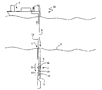
A deep-sea bore 1 in the sea bed 3 is shown in Fig. 1. The deep-sea bore 1
serves for
drilling oil or natural gas and comprises wells 5 which are set on one another
into a well, through
CA 03061168 2019-10-23
9
which the oil or natural gas was brought to the surface. If the deep-sea bore
1 is no longer to be
used for drilling for oil or natural gas, then it must be closed for the
protection of the
environment, so that oil or natural gas cannot flow through the deep-sea bore
1 into the sea. If
however, as is shown here, at well 5 has become damaged or has been pressed in
for example
due to tectonic shifts or a lowering of the seabed inherent of the drilling
for oil, then a plug must
be placed below or distally of such a damage, in order to ensure that no oil
or natural gas escapes
due to the damage. The damage here is shown in the form of a narrowing 6.
Here, it is to be
noted that with regard to the deep-sea bore 1, it does not need necessarily
need to be the case of a
vertical bore, but the deep-sea bore 1 can also be slanted, horizontal and/or
branched.
In order to now be able to place a plug below or distally of the narrowing 6,
the cross
section at the narrowing 6 must be opened to such an extent that a suitable
tool for placing a plug
passes through it. Conventional solutions with a drill cutting head however
are often deflected
laterally at such a narrowing 6 and bind. For this reason, here an abrasive
suspension eroding
system is used in combination with a drilling fluid conduit 9 of a borehole
facility 10, wherein
the drilling fluid conduit 9 is normally envisaged for efficiently conveying
drilled rock to the
surface on drilling with a drilling cutting head. The drilling fluid conduit 9
is brought into the
deep-sea bore 1 via a platform 7 of the borehole facility 10, here in the form
of a ship. An
eroding unit 11 is fluid-connected to the drilling fluid conduit 9 at the
distal end of the drilling
fluid conduit 9. The eroding unit 11 is positioned in the deep-sea bore 1
within the well 5 directly
above the narrowing 6. The eroding unit 11 is mechanically coupled to the
drilling fluid conduit
9 in a manner such that the eroding unit 11 is positionable from the platform
7 by way of rolling
in and rolling out the drilling fluid conduit 9. Herein, the intrinsic weight
of the drilling fluid
conduit 9 and of the eroding unit 11 can be used in the distal direction or an
advance device can
be provided, in particular for the advance given horizontal or relatively non-
steep sections of the
stretch.
The eroding unit 11 comprises a distal nozzle head section 13 and a proximal
anchoring
section 15. The anchoring section 15 can be anchored by way of lateral
anchoring elements 16,
here in the form of toggle levers. The nozzle head section 13 is extendable in
the distal direction
relative to the anchoring section 15. A nozzle head 17 which is rotatable
relative to a nozzle head
base 19 of the nozzle head section 17 is located at the distal end of the
nozzle head section 13.
Several outlet nozzles are arranged at a face side of the nozzle head 17. The
outlet nozzles are
arranged such that exiting erosion jets form a jet fan. On rotation of the
nozzle head 17, each
erosion jet which encloses an angle with the rotation axis R sweeps a cone-
surface-shaped
eroding surface. Concerning erosion jets which have a radially inwardly
directed component and
which intersect the rotation axis R or run skew to this, an eroding surface in
the form of an outer
surface of a rotation body of two cones or truncated cones which lie on one
another with their
tips results.
CA 03061168 2019-10-23
The borehole facility 10 further comprises a drilling fluid return 14, through
which the
drilling fluid together with the eroded material and the abrasive agent is
flushed to the surface to
the platform 7. The drilling fluid thus runs through a circuit, wherein the
drilling fluid which is
delivered to the surface is separated from the eroded material and abrasive
agent on the platform
7 and is processed for reuse.
In Figure 2, another embodiment of a nozzle head 17 is used, in order to
laterally erode
open a well 5, in order to ensure that a concrete plug which is to be poured
in at a later stage is
anchored radially in the rock and that the well cannot be pressed upwards. One
or more exit
nozzles are directed radially outwards for the lateral eroding-open, so that a
disc-like eroding
surface which severs the well 5 at the peripheral side forms on rotation of
the nozzle head 17.
In Figure 3, a fish 20 in the form of a packer is located in the well 5 and
blocks this.
Instead of applying a conventional method for fishing, the fish can be
advancingly eroded by the
eroding unit 11. The erosion jets, to which abrasive agent is added, given
exist pressures of 500
or 700 bar can also erode very hard tool materials. Here, a derrick or a
drilling rig is shown as a
platform 7, in contrast to Figures 1 and 2.
With the embodiment in Figure 4, a so-called side tracking is operated with
the eroding
unit 11. Herein, the eroding unit can be steered into a lateral branching and
can be used there for
eroding blockages or narrowings. The deflecting of the eroding unit 11 into
the branching can
hereby take place via a side-tracing guide 21. It is to be understood that the
deflection takes place
given switched-off eroding jets, so that the side tracking guide 21 is not
advancingly eroded.
In Fig. 5, the circuit of the borehole facility 10 is shown schematically in
more detail. The
components which are located on the platform 7 are represented in dashed
boxes. The eroding
unit 11 which received into the existing borehole facility 1 is connected to
the platform 7 via a
drilling fluid conduit 9 and a signal lead 23. A drilling fluid high-pressure
pump 25 which is
arranged on the platform 7 pumps drilling fluid at a high pressure through the
drilling fluid
conduit 9 to the eroding unit 11. A control unit 27 is signal-connected to the
eroding unit 11 via
the signal lead 23 in order to switch, control, regulate, anchor and/or
advance this. Herein, the
signal lead 23 can be bidirectional, so that not only can the eroding unit 11
receive control
commands but can also send signals of sensors, operating state variables,
error notices, camera
pictures or the like, to the control unit 27. For example, position or speed
meters can measure the
position of actuators for the anchoring elements 16, 53, the speed of the
nozzle head 17 or the
feed speed, temperature sensors control the temperature, acceleration sensors
measure the spatial
orientation, structure-borne sound or infrared sensors scan the environment or
depth and
inclination meters assist in the position evaluation. The obtained information
can be displayed to
CA 03061168 2019-10-23
11
the user by way of the control unit 27 or be used directly for the regulation
and control of the
operation of the eroding unit 11.
Abrasive agent is added to the drilling fluid, so as to be able to use the
drilling fluid
which is available to the eroding unit 11 at a high pressure of 500 - 700 bar
via the drilling fluid
= conduit 9 for abrasive eroding. In the embodiment which is shown in
Figure 5, this takes place
upstream which is to say at the suction side of the drilling fluid high-
pressure pump 25. For this
an abrasive agent supply unit 29 is arranged upstream of the drilling fluid
high-pressure pump 25
between a supply pump 31 and a booster pump 33. The abrasive agent supply unit
29 comprises
a mixing chamber 35 and a refilling funnel 37, wherein abrasive agent can be
filled into the
refilling funnel 37 in a manual or automatic manner and can run into the
mixing chamber 35
which is arranged therebelow. This can take its course in a manner exclusively
on account of
gravity or only assisted by gravity. Alternatively or additionally, a
conveying screw or the like
can be used for leading abrasive agent in a defmed abrasive agent flow into
the mixing chamber
35 in a controlled manner. Alternatively or additionally, the drilling fluid
flow which is produced
by the supply pump 31 and the booster pump 33 can also be used for sucking the
abrasive agent
by way of the Venturi effect in the context of a mixing chamber 35 which
functions as a jet
pump. The abrasive agent is mixed with the drilling fluid within the mixing
chamber 35 and
downstream of the mixing chamber 35 forms a drilling fluid - abrasive agent
suspension which is
suitable for abrasive eroding. Here for example granite sand is a possible
abrasive agent. The
mixing ratio between the abrasive agent and the drilling fluid in the drilling
fluid - abrasive agent
suspension which is suitable for abrasive eroding can lie at about 1:9 and can
be adjustable
depending on the cutting performance requirements or can be set for a certain
application
purpose. At the suction side, the supply pump 31 is connected to a drilling
fluid tank 39, from
which the supply pump 31 obtains the drilling fluid. The drilling fluid tank
39 in turn is filled by
way of already used and recovered drilling fluid.
For this, the drilling fluid - abrasive agent suspension together with eroded
material such
as eroded rock or the material of a fish or of a well wall can brought to the
surface by way of a
suction pump 41 via the drilling fluid return 14 which is received in the
borehole 1. The suction
pump 41 can possibly also only assist an already existing pressure difference
and/or one which is
produced by the drilling fluid high-pressure pump 25, said pressure difference
pressing the
drilling sludge upwards. The drilling fluid which is brought to the surface is
led into a processing
module 43. The processing module 43 comprises a shaker or shale shaker which
separates the
drilling fluid from rock, so that the drilling fluid can be recycled and can
be led from the
processing module 43 into the drilling fluid tank 39. Here, the processing
module 43 also
comprises an abrasive agent separator 44, so that the abrasive agent can also
be reused and
possibly in a direct manner can be fed again in wet or moist form or after a
drying, to the circuit
via the refilling funnel 37. Additionally to the abrasive agent, an additive
such as long-chained
CA 03061168 2019-10-23
12
polymers can also be admixed via the mixing chamber. Such long-chained
polymers can be
water-soluble and can serve for improving the focussing of the erosion jets or
of the abrasive
agent which is contained therein, for increasing the exit speed and for
reducing the wearing in
high-pressure components.
In the embodiment according to Figure 6, the mixing chamber 35 of the abrasive
agent
supply unit 29 is arranged in the circuit downstream of the drilling fluid
high-pressure pump 25.
The abrasive agent supply unit 29 hereby comprises a pressure tank 45 and a
high-pressure pump
47. The pressure tank 45 comprises an abrasive agent - water suspension or
drilling fluid -
abrasive agent suspension which by way of the high-pressure pump 25 is put
under a pressure
which is similar to that produced by the drilling fluid high-pressure pump 25.
The abrasive agent
as described beforehand is led and/or delivered into the mixing chamber 35,
but now under high
pressure. The pressure tank 45 can be designed such that a loading for the
eroding is sufficient,
so that the pressure tank 45 must firstly be relieved of pressure for a
further eroding step, in order
to fill it again for a new eroding step. Alternatively or additionally, the
pressure tank 45 can also
be filled cyclically and in an automatic manner via a lock system, so that a
continuous operation
without pressure relief is possible. Even if this embodiment is more complex
than that which is
shown in Figure 5, here it is advantageous that the drilling fluid high-
pressure pump 25 is not
subjected to an increased wearing due to abrasive agent.
Figures 7a) -f) show an eroding unit 11 in a more detailed manner in different
stages on
eroding a fish 20. Firstly, in a), the eroding unit 11 is positioned in front
of the fish 20, so that the
erosion jets can advancingly erode the fish. 20. For this, the anchoring
section 15, given a
suitable axial position, is anchored laterally with first anchoring elements
16 in the form of
toggle levers. The nozzle head 17 is rotated and the erosion jets of drilling
fluid - abrasive agent
suspension which exit out of the exit nozzles form cone-surface-shaped eroding
surfaces which
advancingly erode the material of the fish 20. For this, the nozzle head 17 at
its distal face side
comprises at least two nozzles with different alignments. A first nozzle 49 is
herein aligned such
that an erosion jet which is directly obliquely radially outwards is produced,
and a second nozzle
51 is herein aligned such that an obliquely radially inwardly directed erosion
jet is produced. The
first nozzle 49 as well as the second nozzle 51 has a distance to the rotation
axis R of the nozzle
head 17. The cone-surface-shaped eroding surface which is produced by the
first nozzle 49 has a
proximal-side cone tip, whereas the cone-surface-shaped eroding surface which
is produced by
the second nozzle 51 has a distal-side cone tip. By way of this, given a
distal advance of the first
nozzle 49 and of the second nozzle 51, the erosion jets can erode once
radially from the inside to
the outside and once radially from the outside to the inside in a
complementary manner and thus
efficiently advancingly erode a volume.
CA 03061168 2019-10-23
13
On eroding, the nozzle head section 13 is extended distally relative to the
anchored
anchoring section 15 so that the cone-surface-shaped eroding surfaces sweep a
volume of the fish
20, in order to hence advancingly erode this. In b), a maximal distal position
of the nozzle head
section 13 relative to the anchoring section 15 is reached, so that the rest
of the fish 20 cannot be
advancingly eroded if the eroding unit 11 is not advancingly driven. This can
be effected via an
advance device or, as is shown in c) and d), via second anchoring elements 53
which in the form
of toggle levers are extended laterally out of the nozzle head section 13 and
anchor the nozzle
head section 13 in the well 5. The first anchoring elements 16 of the
anchoring section 15 are
retracted again. From c) to d), by way of retracting the anchored nozzle head
section 13 into the
anchoring section 15, one succeeds in the no longer anchored anchoring section
15 not pulling
distally to the nozzle head section 13. The control unit 27 which controls all
of this ensures a
corresponding necessary feed of the drilling fluid conduit 9 and of the signal
lead 23. In d), the
nozzle head section 13 is then maximally retracted into the anchoring section
15, so that the
second anchoring elements 53 can be retracted whist the first anchoring
elements 16 can be
extended again (see e)). In e), a further eroding step begins as in a) now for
the remainder of the
fish 20 at a deeper or more distal position. In f), the fish 20 has been
completely advancingly
eroded and the well section can be reached for placing the plug which lies
below the (no longer
existing) fish 20.
Figures 8, 9 and 10 show the nozzle head 17 in more detail. At the proximal
side, the
nozzle head 17 is connectable to the nozzle head base 19 via a pipe connection
55. The pipe
connection 55 is arranged concentrically to the rotation axis R and forms the
feed of drilling fluid
- abrasive agent suspension out of the drilling fluid conduit 9 into the
nozzle head 17. The nozzle
head 17 is itself rotatable with respect to the pipe connection 55, wherein
the longitudinal axis L
of the nozzle head 17 is eccentrically offset with respect to the rotation
axis R. The cylinder-
shaped envelope which with respect to the radius of the nozzle head 17 is
radially enlarged by
this offset and which is swept by the nozzle head 17 on rotation about the
rotation axis R is
represented in a dashed manner. The nozzle head 17 comprises three sections. A
proximal entry
section 57, a distal head section 59 and a middle section 61 which connects
the entry section 57
to the head section 59. The pipe connection 55 leads into a proximal face side
of the entry section
57. A flow guidance element with a spiral-shaped flow channel which brings the
drilling fluid -
abrasive agent suspension into rotation is seated within the middle section
61. The nozzles 49, 51
are arranged at a distal, face side of the head section 59 which here is
preferably provided with at
least one concave deepening 63. In this embodiment, there are two inner
(first) nozzles 49a, 49b
which are aligned inwards, wherein the erosion jet from an inner nozzle 49b
intersects the
rotation axis and the erosion jet from the other inner nozzle 49a runs skew to
the rotation axis R.
Optionally or additionally, the erosion jets here run at a different angle
with respect to the
rotation axis R. Optionally or additionally, there are two outer (second)
nozzles 51a, 51b which
are aligned outwards and whose erosion jets likewise run at a different angle
with respect to the
CA 03061168 2019-10-23
14
rotation axis R. Optionally or additionally, a virtual connection line between
the first inner
nozzles 49a, 49b here does not run perpendicularly to a virtual connection
line between the
second outer nozzles 5a, 51 b (see Fig. 10). Optionally or additionally, the
virtual connection line
between the first inner nozzles 49a, 49b here does not run through the
longitudinal axis L of the
nozzle head 17 and/or not through the rotation axis R. Optionally or
additionally, the distances of
the first inner nozzles 49a, 49b to the longitudinal axis L and/or to the
rotation axis R are
different in each case. In Figure 10, it is illustrated by way of the dashed
cycles with a different
radius that different cone-surface-shaped eroding surfaces are swept by the
respective erosions
jets due to the specific alignment of the second outer nozzles 51a, 5 lb. In
each case the erosion
jets of the first two inner nozzles 51a, 51b sweep different cone-surface-
shaped eroding surfaces.
Figure 11 schematically shows method steps as a flow diagram. Before, after or
during a
letting-down 1101 of an eroding unit into the existing borehole, abrasive
agent is fed 1103 into
the drilling fluid conduit by way of the abrasive agent supply unit,
preferably upstream of the
drilling fluid high-pressure pump 25. The drilling fluid - abrasive agent
suspension which hence
arises is pumped 1105 through the drilling fluid conduit to the eroding unit
and a high-pressure
erosion jet of the drilling fluid - abrasive agent suspension is produced
1107. Material in the
existing borehole is then eroded 1109 by the thus produced high-pressure
erosion jet. All method
steps are preferably carried out in parallel. A distal moving 1111 of the
nozzle head section 13
relative to the anchoring section 15, an anchoring 1113 of the anchoring
section 15 and/or of the
nozzle head section 13 and an eccentric rotating 1115 of the nozzle head 17 is
preferably carried
out parallel to the other method steps.
The numbered indications of the components or movement directions as "first",
"second",
"third" etc. have herein been selected purely randomly so as to differentiate
the components or
the movement directions amongst one another, and can also be selected in an
arbitrarily different
manner. Hence these entail no hierarchy of significance.
Equivalent embodiments of the parameters, components or functions which are
described herein and which appear to be evident to a person skilled in the art
in light of this
description are encompassed herein as if they were explicitly described.
Accordingly, the scope
of the protection of the claims is also to include equivalent embodiments.
Features which are
indicated as optional, advantageous, preferred, desired or similarly denoted
"can"-features are to
be understood as optional and as not limiting the protective scope.
The described embodiments are to be understood as illustrative examples and no
not
represent an exhaustive list of possible alternatives. Every feature which has
been disclosed
within the framework of an embodiment can be used alone or in combination with
one or more
other features independently of the embodiment, in which the features have
been described.
CA 03061168 2019-10-23
Whilst at least one embodiment is described and shown herein, modifications
and alternative
embodiments which appear to be evident to a person skilled in the art in the
light of this
description are included by the protective scope of this disclosure.
Furthermore the term
"comprise" herein is neither to exclude additional further features or method
steps, nor does
"one" exclude a plurality.
CA 03061168 2019-10-23
16
List of reference numerals
1 earth borehole or deep-sea borehole
,
3 sea bed
well
6 narrowing
7 platform
9 drilling fluid conduit
borehole facility
11 eroding unit
13 nozzle head section
14 drilling fluid return
anchoring section
16 first anchoring elements
17 nozzle head
19 nozzle head base
fish
21 side tracking guide
23 signal lead
drilling fluid high-pressure pump
27 control unit
29 abrasive agent supply unit
31 supply pump
33 booster pump
mixing chamber
37 refilling funnel
39 drilling fluid tank
41 suction pump
43 processing module
44 abrasive agent separator
pressure tank
47 high-pressure pump
49 first nozzle
51 second nozzle
53 second anchoring elements
pipe connection
57 entry section
59 head section
CA 03061168 2019-10-23
17
,
61 middle section
63 concave deepening
1101 letting the eroding unit down into the existing borehole
1103 feeding abrasive agent
1105 pumping the drilling fluid - abrasive agent suspension
- 1107 producing a high-pressure erosion jet
1109 eroding material in the existing borehole
1111 distally moving a distal nozzle head section
1113 anchoring a proximal anchoring section
1115 anchoring a distal nozzle head section