Note: Descriptions are shown in the official language in which they were submitted.
- 1 -
DEVICE AND METHOD FOR FIXATING A SUTURE ANCHOR IN HARD
TISSUE
This application is a division of Canadian Patent Application Serial No.
2,811,343
filed September 21, 2011.
FIELD OF THE INVENTION
The invention is in the field of medical technology and concerns a device and
a
method for fixating a suture anchor and therewith a suture in hard tissue in
particular
for attaching, with the aid of the suture, soft tissue to the hard tissue,
wherein the
hard tissue is in particular bone tissue of a human or animal patient. The
invention
also concerns an anchor applicable in the method according to the invention.
BACKGROUND
The publication WO 2009/109057 (Woodwelding) discloses devices and methods for
attaching a suture to hard tissue with the aid of a suture anchor, wherein the
suture
anchor comprises a material having thermoplastic properties and is anchored in
a
hard tissue opening with the aid of vibratory energy used for in situ
liquefaction of
the material having thermoplastic properties. The liquefied material
penetrates into
pores or other suitable structures of the hard tissue in the hard tissue
opening, where
on re-solidification it constitutes a positive fit connection between the hard
tissue and
the suture anchor. The devices as disclosed in the named publication comprise
a
vibration source in a housing, a vibration tool, a guide tube, the anchor, the
suture
and possibly a pushing bush. The proximal end of the vibration tool is coupled
to the
vibration source, the proximal end of the guide tube is supported on the
housing, the
anchor is arranged at the distal end of the vibration tool. The anchor
comprises the
material having thermoplastic properties in the form of a thermoplastic
sleeve, the
anchor or the vibration tool reaching through the sleeve and the sleeve being
clamped
between a foot piece of the anchor and the vibration tool, the guide tube or
the
pushing bush. A suture loop is held in the foot piece of the anchor, two
suture end
CA 3061216 2019-11-11
- 2 -
sections extending through further parts of the anchor and through portions of
the
vibrating tool and the guide tube from where they exit to possibly be kept
straightened or tensioned by being attached to the guide tube or the housing.
For implantation, an opening is provided in the hard tissue and the distal end
of the
device or the suture anchor respectively is introduced into the opening, such
that at
least part of the thermoplastic sleeve is located in the opening, wherein a
cross
section of the opening is slightly larger than the cross section of the
thermoplastic
sleeve such that the material having thermoplastic properties is located near
the hard
tissue of the wall of the opening, but such that, on introducing the anchor
into the
opening, there is no friction between the sleeve and the wall of the opening.
The
vibration source is then activated and the material having thermoplastic
properties of
the thermoplastic sleeve being clamped between a vibrating element (vibration
tool
or anchor foot being coupled to the vibration tool) and a counter element
(anchor
foot not being coupled to the vibration tool, guide tube or pushing bush) is
liquefied
starting from its proximal and/or distal face and flows into the hard tissue,
whereby
the thermoplastic sleeve gets shorter. For maintaining the clamping force on
the
thermoplastic sleeve while the latter is getting shorter, device elements are
moved
relative to each other in an axial direction which is preferably effected by a
pre-
tensioned spring arranged together with at least the thermoplastic sleeve and
the
elements between which the thermoplastic sleeve is clamped in a closed load
frame.
This measure allows automatic anchoring of the suture anchor, the surgeon only
having to position the device with the distal end of the guide tube on the
surface of
the hard tissue and to activate the vibration source. However, special
measures are
needed for allowing checking and tuning of the device before the anchoring
process,
without liquefaction of the material of the thermoplastic sleeve.
The publication US 2009/131947 (Woodwelding) also discloses a method for
attaching a suture to hard tissue with the aid of a suture anchor comprising a
thermoplastic material which is liquefied in situ with the aid of vibratory
energy. The
disclosed method is based on the same principle as the method which is briefly
CA 3061216 2019-11-11
- 3 -
described above, wherein the suture is threaded through a distal end portion
of the
anchor, wherein a proximal end portion of the anchor comprises the
thermoplastic
material, and wherein a proximal face of the anchor is held against a distal
face of a
vibrating tool by pulling suture end portions in a proximal direction.
Further methods and devices for attaching sutures to hard tissue with the aid
of
suture anchors are disclosed in the publications US-7678134, US-7695495, US-
2006/161159, US-2009/192546, US-2009/187216 (all to Arthrex), US-5733307
(Dinsdale), or US-6508830 (Steiner), wherein the disclosed anchors comprise an
interference screw to be screwed into a bone opening provided for the purpose
or a
plug preferably made of bone material and to be press-fitted into a bone
opening
provided for the purpose, wherein the suture is either held by the screw or
plug or by
an additional element being retained in the opening with the aid of the screw
or plug.
Methods of anchoring an item in an opening provided in hard tissue, e.g. in
bone
tissue of a human or animal patient with the aid of a material having
thermoplastic
properties which is liquefied in situ and made to penetrate the hard tissue of
the wall
of the opening are disclosed in the publications US-7335205, US-7008226, US-
2006/0105295, US-2008/109080, US-2009/131947, WO-2009/109057, and WO-
2009/132472.
SUMMARY OF EMBODIMENTS OF THE INVENTION
In accordance with an aspect of at least one embodiment, there is provided a
suture
anchor suitable for being fixed in a hard tissue opening with the aid of a
material
having thermoplastic properties and energy transmitted to the suture anchor
for in
situ liquefaction of at least part of the material having thermoplastic
properties,
wherein the suture anchor comprises an anchor foot and a thermoplastic sleeve,
and
wherein the anchor foot comprises a system of channels with a mouth in a
proximal
face of the anchor foot, the system of channels being suitable for threading a
suture
in form of a loop there through, the thermoplastic sleeve being arranged or
arrangeable coaxially to said mouth, wherein the thermoplastic sleeve
comprises the
CA 3061216 2019-11-11
- 4 -
material having thermoplastic properties and is arranged or arrangable at a
proximal
face of the anchor foot, wherein the suture anchor further comprises a locking
element capable of securing the suture in a non-slideable manner relative to
the hard
tissue and being equipped to be secured relative to the anchor foot when the
anchor
foot is in a fixed state, characterized in that the locking element is a
locking plug and
is welded or weldable into a channel of the system of channels or to the
remains of
the thermoplastic sleeve with the aid of vibrational energy.
In accordance with an aspect of at least one embodiment, there is provided a
device
for fixating a suture anchor in a hard tissue opening with the aid of a
material having
thermoplastic properties and energy transmitted to the suture anchor for in
situ
liquefaction of at least part of the material having thermoplastic properties,
the
device comprising: a tool comprising a distal tool face and an axial channel
with a
distal mouth located in the distal tool face, and a substantially tube-shaped
interface
piece fitting into the axial channel of the tool, wherein the axial channel
and the
interface piece are equipped with catch elements cooperating for catching the
proximal end of the interface piece in the axial channel when the interface
piece is
moved in a proximal direction in the axial channel.
In accordance with an aspect of at least one embodiment, provided are a device
and
method for fixating a suture anchor and therewith a suture in hard tissue,
wherein the
suture fixated in the hard tissue with the aid of the suture anchor is to be
in particular
suitable for attaching soft tissue to the hard tissue, wherein the hard tissue
is in
particular bone tissue of a human or animal patient, and wherein one of the
method
steps comprises in situ liquefaction of a material having thermoplastic
properties and
bringing the liquefied material into contact with the hard tissue. The suture
anchor is
fixated in a hard tissue opening by penetration of the liquefied material into
hard
tissue walls of the opening or it is fixated beyond a hard tissue opening by
the
liquefied material expanding (flowing in radial direction) beyond the opening,
i.e. on
a non-accessible side of a hard tissue layer, possibly combined with
penetrating the
hard tissue surface on this non-accessible side of a hard tissue layer. On re-
CA 3061216 2019-11-11
- 5 -
solidification the material which penetrated into the hard tissue constitutes
a positive
fit connection between this hard tissue and the anchor and/or the material
expanded
beyond the hard tissue opening constitutes a body which cannot pass the
opening.
In accordance with an aspect of at least one embodiment, provided are a device
and a
method for fixating a suture anchor in or beyond an opening in hard tissue of
a
human or animal patient, the suture anchor and the fixation being suitable in
particular for the suture fixated with the aid of the suture anchor to be
slideable
relative to the anchor being fixated in the hard tissue. Therein fixation of
the suture
anchor in the hard tissue, in particular underneath a cortical bone layer is
to be
effected with the aid of a material having thermoplastic properties and being
liquefied in situ to be brought into contact with the hard tissue, in
particular to
penetrate into natural pores (trabecular structure) of the hard tissue or into
suitable
structures or cavities provided in the hard tissue, to preferably form, on re-
solidification, a positive fit connection between the anchor and the hard
tissue..
Device and method according to an embodiment of the invention are to be
suitable in
particular for minimally invasive surgery but are to be applicable in open
surgery
also.
The device provides stability against lateral forces acting on the anchor when
arranged on a distal tool end and does not need a guide sleeve. Furthermore,
it may
comprise means for an easy mechanical and possibly visual control of the
liquefaction of the material having thermoplastic properties. In addition, the
device
according to an embodiment of the invention may comprise a lever system which
is
operated by the surgeon and which facilitates handling of the suture, i.e.
constitutes
means for attaching, tensioning and moving the suture. The device according to
an
embodiment of the invention is easily operated by the surgeon with one hand,
wherein he is able to operate the lever system with one finger of this hand.
The lever
system simplifies not only the implantation process but also the steps for
preparing
the device for the implantation process.
CA 3061216 2019-11-11
- 6 -
The device according to an embodiment of the invention comprises a tool with a
proximal end suitable for being coupled to the energy source and a distal end
suitable
for arrangement of the suture anchor including the suture. In addition, the
device
comprises a substantially tube-shaped interface piece, which serves for
stabilizing the
anchor at the distal end of the tool, such that it can be safely positioned
relative to the
hard tissue and is kept aligned with the tool during the fixation procedure.
The
interface piece is designed to be displaceable in an axial channel of the
distal tool end
during the fixation procedure and to be removable from the fixation site
together
with the tool.
The device may further comprise the anchor including a suture, and possibly
the
energy source, the anchor being arranged at the distal end of the tool and the
energy
source being coupled to the proximal end of the tool. The energy source or a
housing
thereof may carry the above named lever system. The anchor comprises the
material
having thermoplastic properties in form of a thermoplastic sleeve which is
held
between a distal tool face and an anchor foot and which, in the fixation
process, is at
least partly liquefied preferably starting from its proximal face in contact
with the
distal tool face, whereby the liquefied material flows away in a radial
direction to
penetrate hard tissue surrounding the liquefaction location or a cavity
provided in
this hard tissue, or to expand into soft tissue or a cavity beyond the hard
tissue. For
keeping the thermoplastic sleeve in close contact with the distal tool face
during the
liquefaction process the anchor foot is pulled relative to the tool in
proximal direction
with the aid of the suture, which is effected by the surgeon advantageously
with the
aid of the above named lever system.
The interface piece is dimensioned to reach through the thermoplastic sleeve,
a distal
end of the interface piece being couplable or coupled to the anchor foot and a
proximal end reaching into an axial channel of the tool. During the
liquefaction
process the thermoplastic sleeve gets shorter and the anchor foot together
with the
interface piece are moved relative to the tool in a proximal direction. For
mechanical
control of the liquefaction process the tool may comprise a stop against which
the
CA 3061216 2019-11-11
- 7 -
proximal face of the interface piece abuts when the thermoplastic sleeve has
reached
a desired minimal axial length. For an additional visual control the tool may
comprise a lateral recess or a see-through portion adjoining the stop
distally, in
which recess or see-through portion the movement of the proximal end of the
interface piece can be visually controlled, during minimally invasive surgery
through
an arthroscope or during open surgery directly by the surgeon. For being
removable
together with the tool from the fixation site after completion of the
fixation, the
interface piece is caught in the axial channel of the tool at the latest on
completion of
the fixation process, such that it cannot be removed from the channel in a
distal
direction. The anchor foot is preferably connected with the interface piece
with the
aid of a push-on or clip-on connection which holds the two elements together
when
under no load, which stabilizes the two elements relative to each other under
a
compressive load, and which is de-connected easily under a small tensile load.
The suture runs in a loop through a system of channels and/or grooves in the
anchor
foot, the two end sections of the suture protruding from the proximal face
thereof and
running from there through the interface piece and the axial channel of the
tool from
where they exit preferably through the above named recess. The system of
channels
and/or grooves is preferably dimensioned such that the suture is easily
slideable
therethrough and such that, during implantation, the suture comes into contact
neither
with the hard tissue in the tissue opening nor with the liquefied material.
This
measure achieves that neither friction on the hard tissue nor thermal or
mechanical
influence of the liquefied or re-solidified material of the thermoplastic
sleeve will
impair the slideability of the suture through the implanted anchor. This does
not only
mean that after anchorage of the suture anchor the suture is held slideably by
the
latter but it also means that the suture may well be of a friction and/or heat
sensitive
type, consisting e.g. of a material having similar characteristics as the
material of the
thermoplastic sleeve.
For the fixation process the tool is preferably supported on the hard tissue.
For
achieving liquefaction underneath a cortical bone layer or on a non-accessible
side of
CA 3061216 2019-11-11
- 8 -
a bone plate, the tool comprises a step at a distance from the distal tool
face adapted
to the thickness of the cortical bone layer or the bone plate. Therein the
tool portion
on the distal side of the step has a cross section smaller than the cross
section of the
opening and a tool portion on the proximal side of the step has a cross
section larger
than the cross section of the opening, such that the step limits introduction
of the
distal device end into the hard tissue opening by abutting against the hard
tissue
surface, when the interface between the distal tool face and the proximal face
of the
thermoplastic sleeve and therewith the liquefaction location is situated just
below the
cortical bone layer or on the other (non-accessible) side of the bone plate.
During the
liquefaction process, the tool is kept in the same position.
The energy source is preferably a vibration source, in particular a source of
ultrasonic vibration (e.g. piezoelectric vibration generator possibly
comprising a
booster to which the tool is coupled) and the tool is suitable for
transmission of the
vibration from its proximal end to its distal face, preferably such that the
distal face
vibrates with a maximal longitudinal amplitude. For the in situ liquefaction
the
proximal face of the thermoplastic sleeve is held against the vibrating distal
tool face
such creating friction heat at the interface. It is possible also to activate
the tool to
vibrate in a radial or in a rotational direction.
Alternatively, the energy source may be a laser, preferably emitting laser
light in the
visible or infrared frequency range and the tool is equipped for transmitting
this light
to its distal end, preferably via glass fiber. For the in situ liquefaction
the laser light
is absorbed near the distal tool face or in the thermoplastic sleeve held
against the
distal tool face, wherein in the latter case the material of the thermoplastic
sleeve
may contain particles or substances effecting such absorption. Furthermore,
the
energy source may be a source of electric energy which e.g. heats an electric
resistor
in a distal tool portion or which causes eddy currents and therewith thermal
energy
near the distal tool face or in the thermoplastic sleeve.
Suitable in situ liquefaction of a material having thermoplastic properties
with the aid
of vibration energy combined with an acceptable thermal loading of the tissue
and
CA 3061216 2019-11-11
- 9 -
suitable mechanical properties of the positive fit connection to be produced
is
achievable by using materials with thermoplastic properties having an initial
modulus of elasticity of at least 0.5 GPa and a melting temperature of up to
about
350 C in combination with vibration frequencies preferably in the range of
between
2 and 200 kHz (preferably 15 to 40 kHz, or even more preferably between 20 and
30
kHz). The modulus of elasticity of at least 0.5 GPa is in particular necessary
if the
material having thermoplastic properties is to transmit the vibration or
mechanical
forces without loss of mechanical stiffness. If the material having
thermoplastic
properties is not to transmit the vibration but is to be liquefied where it is
in direct
contact with the vibrating tool or if the material having thermoplastic
properties is to
transmit the vibration or mechanical forces but is supported and guided by
device
parts of other materials, the material having thermoplastic properties may
have a
considerably smaller modulus of elasticity.
Materials having thermoplastic properties suitable for the thermoplastic
sleeve of the
device and the method according to an embodiment of the invention are
thermoplastic polymers, e.g.: resorbable or degradable polymers such as
polymers
based on lactic and/or glycolic acid (PLA, PLLA, PGA, PLGA etc.) or
polyhydroxy
alkanoates (PHA), polycaprolactone (PCL), polysaccharides, polydioxanes (PD)
polyanhydrides, polypeptides or corresponding copolymers or composite
materials
containing the named polymers as a component; or non-resorbable or non-
degradable
polymers such as polyolefines (e.g. polyethylene), polyacrylates,
polymetacrylates,
polycarbonates, polyamides, polyester, polyurethanes, polysulfones,
polyarylketones,
polyimides, polyphenylsulfides or liquid crystal polymers LCPs, polyacetales,
halogenated polymers, in particular halogenated polyolefines,
polyphenylensulfides,
polysulfones, polyethers or equivalent copolymers or composite materials
containing
the named polymers as a component.
Specific embodiments of degradable materials are Polylactides like LR706
PLDLLA
70/30, R208 PLDLA 50/50, L2 10S, and PLLA 100% L, all of Btihringer. A list of
suitable degradable polymer materials can also be found in: Erich Wintermantel
und
CA 3061216 2019-11-11
- 10 -
Suk-Woo Haa, "Medizinaltechnik mit biokompatiblen Materialien und Verfahren",
3.
Auflage, Springer, Berlin 2002 (in the following referred to as
"Wintermantel"), page
200; for information on PGA and PLA see pages 202 if., on PCL see page 207, on
PHB/PHV copolymers page 206; on polydioxanone PDS page 209. Discussion of a
further bioresorbable material can for example be found in CA Bailey et al., J
Hand
Surg [Br] 2006 Apr;31(2):208-12.
Specific embodiments of non-degradable materials are Polyetherketone (PEEK
Optima,
Grades 450 and 150, lnvibio Ltd), Polyetherimide, Polyamide 12, Polyamide 11,
Polyamide 6, Polyamide 66, Po
lycarbonate, Polymethylmethacrylate,
Polyoxymethylene, or polycarbonate-urethane (e.g. Bionate by DSM, in
particular types
65D and 75D). An overview table of polymers and applications is listed in
Wintermantel, page 150; specific examples can be found in Wintermantel page
161 if.
(PE, Hostalen Gur 812, Hochst AG), pages 164 if (PET) 169ff. (PA, namely PA 6
and
PA 66), 171 if. (PTFE), 173 ff. (PMMA), 180 (PUR, see table), 186 if. (PEEK),
189
(PSU), 191 if (POM ¨ Polyacetal, tradenarnes Delrin, Tenac, has also been used
in
endoprostheses by Protec).
The material having thermoplastic properties may further contain foreign
phases or
compounds serving further functions. In particular, the thermoplastic material
may be
strengthened by admixed fibers or whiskers (e.g. of calcium phosphate ceramics
or
glasses) and such represent a composite material. The material having
thermoplastic
properties may further contain components which expand or dissolve (create
pores) in
situ (e.g. polyesters, polysaccharides, hydrogels, sodium phosphates),
compounds
which render the implant opaque and therewith visible for X-ray, or compounds
to be
released in situ and having a therapeutic effect, e.g. promotion of healing
and
regeneration (e.g. growth factors, antibiotics, inflammation inhibitors or
buffers such as
sodium phosphate or calcium carbonate against adverse effects of acidic
decomposition). If the thermoplastic material is resorbable, release of such
compounds
is delayed. If the device is to be anchored not with the aid of vibration
energy but with
the aid of electromagnetic radiation, the liquefiable material having
thermoplastic
CA 3061216 2019-11-11
- 11 -
properties may locally contain compounds (particlulate or molecular) which are
capable
of absorbing such radiation of a specific frequency range (in particular of
the visible or
infrared frequency range), e.g. calcium phosphates, calcium carbonates, sodium
phosphates, titanium oxide, mica, saturated fatty acids, polysaccharides,
glucose or
mixtures thereof.
Fillers used may include degradable, osseostimulative fillers to be used in
degradable
polymers, including: P-Tricalciumphosphate (TCP), Hydroxyapatite (HA, <90%
crystallinity); or mixtures of TCP, HA, DHCP, Bioglasses (see Wintermantel).
Osseo-
integration stimulating fillers that are only partially or hardly degradable,
for non
degradable polymers include: Bioglasses, Hydroxyapatite (>90% cristallinity),
HAPEX , see SM Rea et al., J Mater Sci Mater Med. 2004 Sept;15(9):997-1005;
for
hydroxyapatite see also L. Fang et al., Biomaterials 2006 Jul; 27(20):3701-7,
M. Huang
et al., J Mater Sci Mater Med 2003 Jul;14(7):655-60, and W. Bonfield and E.
Tanner,
Materials World 1997 Jan; 5 no. 1:18-20. Embodiments of bioactive fillers and
their
discussion can for example be found in X. Huang and X. Miao, J Biomater App.
2007
Apr; 21(4):351-74), JA Juhasz et al. Biomaterials, 2004 Mar; 25(6):949-55.
Particulate
filler types include: coarse type: 5-2011m (contents, preferentially 10-25% by
volume),
sub-micron (nanofillers as from precipitation, preferentially plate like
aspect ratio > 10,
10-50 rim, contents 0.5 to 5% by volume). Experiments show that liquefaction
with the
aid of ultrasonic vibration energy allows filling the thermoplastic polymer to
a relatively
high degree without impairing the capability of the liquefied material to
penetrate
structures as e.g. the trabecular structure of viable cancellous bone.
Anchor portions other than the thermoplastic sleeve may consist of any
suitable
material (e.g. polymer, metal, ceramic, glass) which material may be bio-
resorbable or
not bio-resorbable and liquefiable or not liquefiable. Non-bioresorbable or
non-
biodegradable such materials may comprise surfaces equipped for furthering
osseointegration (e.g. per se known surface structures or coatings) where in
contact
with the bone tissue, in particular if the material of the thermoplastic
sleeve is bio-
resorbable or bio-degradable and therefore the anchoring function needs to be
CA 3061216 2019-11-11
- 12 -
gradually taken over by osseointegration. Good results have e.g. been achieved
with
anchor feet of polylactic acid (PLA) filled with Hydroxyapatite or
calciumphosphates, in particular of PLLA filled with 60% tricalciumphosphate
or
PDLLA 70%/30% (70%L and 30%D/L) filled with 30% biphasic calciumphosphate,
combined with thermoplastic sleeves of PLDLLA 70%/30% (70%L and 30% D/L),
as available from Bohringer as LR706. The PDLLA 70%/30% filled with 30% of
biphasic calciumphosphate and similar materials prove to be suitable also for
the
thermoplastic sleeve and therefore suitable for manufacturing bio-resorbable,
one-
piece anchors being made of one material only.
As the tool can be designed very slim and with an axial length of 200 mm or
even
longer, device and method according to an embodiment of the invention are in
particular suitable for minimally invasive surgery but are also applicable in
open
surgery. If the tool is a vibration tool it preferably has a length
corresponding to half
of the vibration wavelength in the tool material (or a multiple thereof). This
half of
the vibration wavelength is e.g. in titanium grade 5 and at a vibration
frequency of 20
kHz 126.5 mm.
Device and method according to an embodiment of the invention as far as above
described are applicable for all surgical procedures in a human or animal
patient, in
which surgical procedure a suture needs to be attached to hard tissue, in
particular
attached to be at least primarily slideable relative to the implanted anchor,
and in
particular to bone tissue with a cortical bone layer wherein the fixation of
the anchor
is preferably achieved underneath the cortical bone layer (so called sub-
cortical
fixation) in cancellous bone situated underneath the cortical bone layer, on
the inner
side of the cortical bone layer, or in a cavity or soft tissue adjoining the
cortical bone
layer on its inner side. In the same manner, device and the method according
to an
embodiment of the invention are applicable for attaching a suture to a
replacement
material having features comparable to the features of hard tissue, or to part
hard
tissue part replacement material, or to a further implant (e.g.
endoprosthesis) wherein
the implant needs to be suitably equipped, e.g. with undercut openings. An
example
CA 3061216 2019-11-11
- 13 -
of such an application is the fixation of a soft tissue end to a bone, e.g.
fixation of a
rotator cuff to underlying bone tissue (or a corresponding endoprosthesis),
Achilles
tendon repair, or fixation of another ligament or tendon end to bone tissue
using the
technique of the so called double row procedure. For this procedure sutures
are
slideably attached to the bone by a row of medial anchors, are passed through
the
soft tissue, tensioned and, crossing each other, are non-slideably fixed
(locked) with
the aid of a row of lateral anchors, this second row running substantially
parallel to
the row of medial anchors.
When using the above discussed device and method according to an embodiment of
the invention for the slideable attachment of the sutures, i.e. for anchoring
the medial
anchors, with the aid of the material having thermoplastic properties and
preferably
vibration energy it is advantageous to use a similar technique for the non-
slideable
attachment or locking of the sutures, i.e. for anchoring the lateral anchors,
also.
As described further below, it is possible also to use the device and the
method
according to an embodiment of the invention not only for sideable fixation of
a
suture relative to a hard tissue but also for non-slideable such fixation or
locking of
the suture relative to the hard tissue respectively.
According to an embodiment there is provided a device for fixating a suture
anchor
in a hard tissue opening with the aid of a material having thermoplastic
properties
and energy transmitted to the suture anchor for in situ liquefaction of at
least part of
the material having thermoplastic properties, the device comprising: a tool
comprising a distal tool face and an axial channel with a distal mouth located
in the
distal tool face, and a substantially tube-shaped interface piece fitting into
the axial
channel of the tool, wherein the axial channel and the interface piece are
equipped
with catch elements cooperating for catching the proximal end of the interface
piece
in the axial channel when the interface piece is moved in a proximal direction
in the
axial channel. In an embodiment the catch element is arranged at a proximal
end of
the interface piece. In an embodiment the tool further comprises a stop in the
axial
channel capable of limiting proximal movement of the interface piece, and,
adjoining
CA 3061216 2019-11-11
- 14 -
the stop distally, an inspection portion allowing visual inspection of the
axial channel
in a radial direction. In an embodiment the inspection portion comprises a
lateral
recess of a depth reaching into the axial channel. In an embodiment a tool
portion
adjoining the recess proximally comprises an axially extending groove being
aligned
with the recess. In an embodiment the tool is a sonotrode coupled or couplable
to a
source of vibration energy, in particular to a generator of ultrasonic
vibration. In an
embodiment the tool comprises a rod portion and a coupling portion, a proximal
end
of the rod portion being fixed in an axial bore of the coupling portion and
the
coupling portion comprising a bolt for being capable to be coupled to the
source of
vibration energy. In an embodiment the device further comprising the suture
anchor
and a suture, wherein the suture anchor comprises an anchor foot and a
thermoplastic
sleeve, wherein the anchor foot comprises a system of channels and/or grooves,
the
suture extending in the form of a loop through the system, wherein the
thermoplastic
sleeve comprises the material having thermoplastic properties and is situated
between the distal face of the tool and a proximal face of the anchor foot,
wherein the
interface piece extends from the anchor foot through the thermoplastic sleeve
and
into the axial channel and end portions of the suture extend from the anchor
foot
through the interface piece, and wherein the anchor foot, the thermoplastic
sleeve
and the interface piece are held relative to the distal end of the tool by the
end
portions of the suture being held in a more proximal position and/or by the
interface
piece being caught in the axial channel of the tool. In an embodiment the
suture
anchor is a one-piece item made of one only material. In an embodiment the
suture
is slideably held in the system of channels and/or grooves. In an embodiment
the
catch elements are arranged to be able to catch the interface piece in the
axial
channel when the thermoplastic sleeve has an initial axial length, or only
when the
thermoplastic sleeve is shortened through liquefaction of the material having
thermoplastic properties. In an embodiment the device further comprising the
energy
source and means for fixing end sections of a suture, for straightening or
tensioning
the suture, and for moving the anchor foot with the aid of the suture. In an
embodiment said means for fixing, straightening or tensioning and moving
comprise
CA 3061216 2019-11-11
- 15 -
a lever system with a clamping arm and a tensioning arm, the clamping arm
being
attached to the housing, the energy source, or the tool in a pivoting manner,
the
tensioning arm being connected to a free end of the clamping arm in an
articulating
manner, and further comprising means for fastening the end sections of the
suture
relative to the lever system and locking means for locking the clamping arm
and the
tensioning arm in a clamping position.
According to an embodiment there is provided a method for fixating a suture
anchor
in a hard tissue opening with the aid of a material having thermoplastic
properties
and energy transmitted to the suture anchor for in situ liquefaction of at
least part of
the material having thermoplastic properties using a device according to an
embodiment described above, the method comprising the steps of: providing a
hard
tissue opening having a cross section slightly larger than a cross section of
the suture
anchor, coupling a proximal end of the tool to an energy source; straightening
or
tensioning the suture by pulling end sections thereof in a proximal direction,
positioning a distal portion of the device in the hard tissue opening such
that the
distal face of the tool is positioned in the hard tissue opening, activating
the energy
source, thereby starting liquefaction of the material having thermoplastic
properties,
keeping the energy source active and moving the anchor foot relative to the
tool in
proximal direction with the aid of the suture being kept straightened or
tensioned, as
the thermoplastic sleeve gets shorter through further liquefaction, for a time
sufficient to liquefy at least part of the thermoplastic sleeve, and de-
activating the
energy source and releasing the end sections of the suture, and removing the
distal
end of the tool together with the interface piece being caught in the axial
channel of
the tool from the hard tissue opening. In an embodiment, in the step of
positioning, a
distal face of the tool is positioned within the hard tissue opening, and
wherein the
distal face of the tool and/or the thermoplastic sleeve are designed for
starting
liquefaction at the proximal face of the thermoplastic sleeve. In an
embodiment,
during the step of keeping and moving, the tension of the suture is kept
constant. In
an embodiment the step of keeping and moving is ended, when the proximal end
of
the interface piece abuts against a stop arranged in the axial channel or
reaches a
CA 3061216 2019-11-11
- 16 -
predetermined location in the axial channel, or when the thermoplastic sleeve
is fully
liquefied, or when the suture tension reaches a predefined upper limit. In an
embodiment, in the step of providing the hard tissue opening, the anchor foot
is
forced into the hard tissue. In an embodiment, in the step of positioning, the
distal
face of the tool is positioned in a depth corresponding approximately to the
thickness
of a cortical bone layer or beyond a bone plate and is kept in this position
during the
step of keeping and moving, such that the material having thermoplastic
properties
after liquefaction and re-solidification forms an anchorage in cancellous bone
tissue
underneath the cortical bone layer or a button in a cavity underneath the
cortical bone
layer or beyond the bone plate, the button having a cross section larger than
the cross
section of the opening. In an embodiment the method further comprising a step
of
locking the suture relative to the suture anchor fixated in the hard tissue by
fixing a
locking element to the anchor foot or to remains of the thermoplastic sleeve.
In an
embodiment the locking element is a locking plug being welded with the aid of
vibrational energy into a channel of the system of channels and/or grooves or
to the
remains of the thermoplastic sleeve. In an embodiment the suture is an
auxiliary
suture used for fixation of the suture anchor and wherein a further suture is
threaded
through the anchor foot with the aid of the auxiliary suture and tensioned
before the
step of locking. In an embodiment the method further comprising a step of
securing
an edge of a mouth of the hard tissue opening by fixing a securing sleeve to
remains
of the thermoplastic sleeve. In an embodiment the method constituting fixation
of at
least one of a row of medial anchors in a double row procedure.
According to an embodiment there is provided a suture anchor suitable for use
with
the device and method described above, comprising an anchor foot and a
thermoplastic sleeve, the anchor foot comprising a system of channels and/or
grooves with a mouth in a proximal face of the anchor foot, the system being
suitable
for threading a suture in form of a loop therethrough, the thermoplastic
sleeve being
arranged or arrangeable coaxially to said mouth. In an embodiment the suture
anchor consisting fully of one material having thermoplastic properties and
being
suitable for in situ liquefaction with the aid of vibratory energy, in
particular with
CA 3061216 2019-11-11
- 17 -
ultrasonic vibratory energy. In an embodiment the suture anchor according
constituting one piece being made of PLDLLA 70%/30% filled with up to 30% of
biphasic calciumphosphate.
BRIEF DESCRIPTION OF THE DRAWINGS
Device and method according to embodiments of the invention are described in
further detail in connection with the appended Figs., wherein:
Fig. 1 illustrates an exemplary embodiment of the
device
according to the invention by showing a distal portion of
the device before the anchoring procedure and after the
anchoring procedure, this distal device portion comprising
a distal portion of the tool, the interface piece, the suture
anchor and the suture running through the anchor;
Fig. 2 shows the suture anchor as shown in Fig. 1 being
fixated
in the hard tissue opening;
Fig. 3 shows a further exemplary embodiment of the
distal tool
portion and the interface piece of a device according to the
invention;
Figs. 4 and 5 further illustrate an exemplary embodiment of the device
according to the invention by showing an exemplary
embodiment of the proximal portion of the device
comprising a proximal portion of the tool, the energy
source with the housing and, attached to the housing, the
lever system for fastening and tensioning the suture and
for moving the anchor foot with the aid of the suture;
CA 3061216 2019-11-11
- 18 -
Fig. 6
illustrates a further exemplary embodiment of the method
according to the invention and of the anchor being fixated
with the aid of the methods;
Fig. 7
illustrates four successive phases of the per se known
double row procedure using the example of a rotator cuff
repair;
Fig. 8 shows
the fixated anchor as shown in Fig. 2 and further
equipped with a locking plug for locking the suture
relative to the anchor;
Fig. 9 illustrates a further
exemplary embodiment of the method
according to the invention wherein the suture is locked
relative to the anchor with the aid of a locking plug;
Fig. 10 shows
the fixated anchor as shown in Fig. 2 and further
equipped with a securing sleeve preventing damage of the
edge of the mouth of the hard tissue opening by the suture
or of the suture by this edge;
Fig. 11 shows
a preferred embodiment of a suture anchor
applicable in the device and method according to the
invention;
Figs. 12 to 15 show the proximal end portion of a vibration tool which is
e.g. applicable in the device and method according to an
embodiment of the invention.
DESCRIPTION OF THE PREFERRED EMBODIMENTS
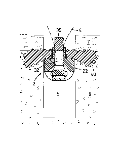
Figure 1 shows a distal portion of an exemplary embodiment of the device
according
to the invention and illustrates in section the distal end of a tool 1, the
suture anchor
2 and the interface piece 3. Also illustrated is the suture 4 (shown as dash-
dotted
CA 3061216 2019-11-11
- 19 -
line), which runs in a loop through the anchor 2, suture end sections
extending
through the interface piece 3 and through parts of the tool 1. The distal
device
portion is shown positioned relative to the hard tissue opening 5 before the
liquefaction and anchoring process (left hand side of Fig. 1) and after this
process
(right hand side of Fig. 1), wherein the hard tissue opening 5 is e.g. an
opening in
bone tissue and reaches from a bone surface 6 through a cortical bone layer 7
into
cancellous bone tissue 8.
The tool 1 comprises at its distal end a distal tool face 10 and extending
axially from
the distal tool face an axial channel 11. The axial channel 11 comprises a
first catch
element 12, e.g. a wedge-shaped protrusion and in proximal direction following
the
first catch element 12 a stop 13 which ends the axial channel 11 or closes it
at least
partially. The stop 13 is constituted in the illustrated case by the proximal
wall of a
lateral recess 14, the recess opening the axial channel 11 laterally for
visual
inspection. The tool portion adjoining the lateral recess 14 in proximal
direction
comprises a groove 15 aligned with the lateral recess 14 for accommodation of
the
suture 4. The tool 1 preferably further comprises an outer step 16, separating
a distal
end portion 17 of the tool 1 having a smaller cross section from a proximally
adjoining portion having a larger cross section. As illustrated in Fig. 1, it
is sufficient
for the step 16 to extend only around part of the tool circumference. However
it may
also run around the whole tool circumference.
The suture anchor 2 comprises the anchor foot 22 and the thermoplastic sleeve
23,
wherein the anchor foot 22 and the thermoplastic sleeve 23 may be separate
items or
wherein anchor foot 22 and thermoplastic sleeve 23 may constitute one piece.
The
anchor foot 22 comprises a system of channels and/or grooves 25 through which
the
suture 4 runs in a preferably slideable loop entering and exiting through the
proximal
face of the anchor foot 22. As illustrated in Fig. 1, the system of channels
and/or
grooves comprises e.g. a transversal first channel 30 extending substantially
perpendicular to the anchor foot axis, and in the region of both mouths of
this first
channel 30 recesses 31 or grooves, as well as an axial second channel 32
extending
CA 3061216 2019-11-11
- 20 -
to the proximal face of the anchor foot 22 and being connected to the recesses
31 or
grooves through angled third channels 33.
For accommodation of more than one suture 4 the system of channels and/or
grooves
25 may comprise more than one transversal first channels 30 being arranged
axially
spaced from each other and either parallel to each other or angled.
The interface piece 3 is substantially tube shaped and designed to extend
loosely
through the thermoplastic sleeve 23. The interface piece is coupled (or
couplable) at
a distal end to the anchor foot 22 and reaches beyond the proximal sleeve face
when
the distal sleeve face sits on the proximal face of the anchor foot 22.
Coupling of the
anchor foot 22 and the interface piece 3 is effected e.g. as illustrated
between a tube-
shaped anchor foot protrusion into which a distal end portion of the interface
piece 3
is e.g. press-fitted. Instead of such press-fit coupling any per se known clip-
on
connection is applicable for which e.g. the distal end of the interface piece
3
comprises a ring-shaped ridge and the tube-shaped anchor foot protrusion
comprises
a ring-shaped groove adapted to the ridge. At its proximal end, the interface
piece 3
comprises a second catch element 12', e.g. a depression, adapted to the first
catch
element 12 in the axial channel 11 of the tool 1 and cooperating with this
first catch
element 12 in a manner as described further below.
The suture anchor 2 is arranged at the distal end of the tool 1 with the
proximal end
of the interface piece 3 extending into the axial channel 11 of the tool 1 and
the
suture 4 extending from the proximal face of the anchor foot 22 through the
interface
piece 3 into the recess 14 of the tool 1 and from there into the groove 15.
The
thermoplastic sleeve 23 is kept between the distal face 10 of the tool 1 and
the anchor
foot 22 by the end sections or the suture 4 being held at a proximal end of
the tool
(see e.g. Fig. 4). The axial lengths of the interface piece 3, the
thermoplastic sleeve
23 and the tool section adjoining the recess 14 in a distal direction are
adapted to
each other such that the proximal face of the interface piece 3 is just about
visible in
the recess 14, when the thermoplastic sleeve 23 has an initial maximum length.
The
stop 13 is distanced from the named position of the proximal face of the
interface
CA 3061216 2019-11-11
- 21 -
piece 3 by the length of the thermoplastic sleeve 23 which is to be liquefied.
The
catch elements 12 and 12' are arranged such that they catch each other before
the
proximal face of the interface piece 3 abuts the stop 13, the cooperating
catch
elements limiting distal movement of the interface piece 3 relative to the
tool such
that the interface piece cannot be removed from the channel 11, but possibly
allowing further proximal movement.
In the case of the use of vibrational energy for the liquefaction process, it
is
advantageous to equip the distal face 10 of the tool 1 (or the proximal face
of the
thermoplastic sleeve 23) with energy directors, e.g. with an edge which limits
contact
with the thermoplastic sleeve to a line, and/or to rigidly attach the distal
face of the
thermoplastic sleeve 23 to the anchor foot 22, which is easily possible if the
anchor
foot 22 is made of a thermoplastic material, e.g. of PEEK to which the
thermoplastic
sleeve 23 can be welded. It is also possible to produce anchor foot and
thermoplastic
sleeve as one piece consisting of the material having thermoplastic properties
only
(see also Fig. 11), e.g. of a polylactide polymer, e.g. PDLLA, preferably
PDLLA
70%/30% filled with up to 30% of biphasic calciumphosphate. All the named
measures help to ensure limitation of the liquefaction of the thermoplastic
sleeve 23
to its proximal face. In an anchor foot made of a polymer prone to creep it
may be
advantageous to strengthen the area most loaded by the suture tension, e.g. by
lining
the transverse suture channel 30 with a tube of a more resistant material such
as e.g.
a polylactide of a higher cristallinity or PEEK or by positioning a portion of
such a
material proximal to the transverse suture channel 30.
As it is most convenient to provide the hard tissue opening 5 for anchoring
the suture
anchor 2 by drilling, the anchor and at least the distal end portion 16 of the
tool
which is to be positioned in the opening 5 have advantageously a circular
cross
section. The same applies to the anchor foot 22, the interface piece 3 and the
axial
channel therethrough, as well as to the thermoplastic sleeve 23 and the axial
channel
11 of the tool 1. However this is not a condition for the invention, according
to which
any one of the named items may have a non-circular cross section. The only
CA 3061216 2019-11-11
- 22 -
condition regarding cross sections is the condition for the thermoplastic
sleeve 23
which is to fit into the opening 5 such that a sufficient part of the material
to be
liquefied is situated close to the wall of the opening 5. The cross section of
the distal
end portion 17 of the tool 1 and the cross section of the anchor foot 22 are
preferably
the same as the cross section of the thermoplastic sleeve 23 or they are
slightly
smaller than the latter.
For fixating the suture anchor 2 in the hard tissue opening 5 and therewith
attaching
the suture 4 relative to the hard tissue surface 6, the device according to an
embodiment of the invention is positioned relative to the bone opening 5 as
illustrated on the left hand side of Fig. 1. The energy source is coupled to
the
proximal end of the tool 1 (not shown), the interface piece 3 and the anchor 2
are
arranged at the distal tool end with the suture 4 extending through the anchor
foot 22,
the interface piece 3, the axial channel 11 of the tool 1 and the recess 14
and is held
further proximally to be at least straightened or slightly tensioned, such
that the
thermoplastic sleeve 23 is held between the proximal face 10 of the tool 1 and
the
anchor foot 22, and the tool 1 is positioned such that step 16 abuts against
the bone
surface 6. For starting liquefaction of the thermoplastic sleeve 23 the energy
source
is activated and possibly the suture tension increased. The liquefied material
flows
radially away from anchor 2 and tool 1 and the thermoplastic sleeve 23 gets
shorter
and is kept in contact with the distal face 10 of the tool 1 by pulling the
suture 4 in a
proximal direction and therewith pulling the anchor foot 22 nearer to the
distal tool
face 10, while the step 16 remains in contact with the bone surface 6.
The principle of the anchoring process is described (for different
applications) e.g. in
the publication US-2009/131947.
When working with a vibration tool and with a friction and/or heat sensitive
suture it
is particularly important not to tension the suture on activation of the
energy source,
but only when the proximal face of the thermoplastic sleeve is at least warmed
such
that it cannot transmit the vibration further distally or at least not fully.
If the suture
is tensioned at the moment of starting the vibration, it may happen that the
vibrations
CA 3061216 2019-11-11
- 23 -
are transmitted through the thermoplastic sleeve into the anchor foot which
then
vibrates relative to the suture. This may damage a sensitive suture before
liquefaction
of the thermoplastic sleeve starts. Further measures for preventing vibration
transmission to the anchor foot are energy directors at the interface between
the tool
1 and the thermoplastic sleeve as described further above and/or start of the
vibration
with a smaller starting amplitude which is increased after a starting interval
in which
the proximal end of the thermoplastic sleeve is warmed up.
With the liquefaction process advancing and the thermoplastic sleeve 23
getting
shorter and the anchor foot 22 being pulled in a proximal direction, the
interface
piece 3 advances in the axial channel 11 of the recess 14 respectively, until
the catch
elements 12 and 12' come into catching interaction with each other and the
proximal
face of the interface piece abuts against the stop 13, which signifies the end
of the
liquefaction process as shown on the right hand side of Fig. 1. The
advancement of
the proximal end of the interface piece 3 and therewith the liquefaction
process can
be visually controlled in the recess 14.
At the end of the liquefaction process, the thermoplastic sleeve 23 has a
minimal
axial length and the liquefied and re-solidified material 40 of the
thermoplastic
sleeve 23 extends radially into the cancellous bone 8 and/or anchors the
suture
anchor 2 securely on the inside of the cortical bone layer 7. Furthermore, the
interface piece 3 is caught in the axial channel 11 of the tool 1, which means
on
removing the tool 1 from the anchored suture anchor, the interface piece 3 is
removed together with the tool 1.
For making sure that the suture 4 is not clamped between the proximal end of
the
interface piece 3 and the stop 13, when the proximal face of the interface
piece abuts
the stop 13, it is advantageous to design this proximal face and/or the stop
13
sloping, such that abutment of the interface piece 3 on the stop occurs only
at the
bottom of the recess 14, while the suture 4 is pulled away from this bottom,
i.e.
towards the opening of the recess 14. The named form of the proximal face of
the
interface piece 3 also results in an easier resiliency of the abutting portion
of the
CA 3061216 2019-11-11
- 24 -
proximal face of the interface piece 3 which can be made use of for the design
of the
second catch element 12'.
After completion of the liquefaction process, the suture 4 is released from
being
tensioned and held, and the tool 1 together with the interface piece 3 is
removed from
the opening 5 in which the suture anchor 2 is now safely anchored, and the
suture is
slideably attached to the bone tissue.
Figure 2 shows the result of the method as illustrated in Fig. 1, i.e. the
suture 4 being
attached to the hard tissue with the aid of the suture anchor 2 being anchored
in the
hard tissue opening 5 by the re-solidified material 40 situated in the hard
tissue or
bone tissue surrounding the opening, in particular in the cancellous bone
tissue 8 just
underneath the cortical bone layer 7 (subcortical fixation), the re-solidified
material
40 being connected to remains of the thermoplastic sleeve 23. Obviously, the
fixation
process according to an embodiment of the invention is not dependent on the
quality
of the cancellous bone 8, which may even be completely absent. In the latter
case the
liquefied material may or may not penetrate the inner surface of the cortical
bone
layer and be held in the hard tissue opening mainly by the fact of
constituting after
re-solidification a body which cannot pass through the opening any more. This
means that the fixation according to an embodiment of the invention is
suitable not
only for a subcortical fixation in cancellous bone of a reduced mechanical
stability
but also in absence of cancellous bone e.g. in the medullary cavity of long
bones or
on a non-accessible side of a bone plate.
Figure 3 shows an alternative embodiment of the catch mechanism and the stop
mechanism between the tool 1 and the interface piece 3 of a device according
to the
invention. The tool again comprises an axial channel 11 which extends at least
through a distal tool portion and in which the substantially tubular interface
piece 3
extends, and it comprises a recess 14 in which the proximal end of the
interface piece
3 moves in proximal direction during the liquefaction process. The first catch
element 12 is constituted by the tool face at the distal side of the recess
14, the
second catch element 12' is arranged on a proximal protrusion of the interface
piece
CA 3061216 2019-11-11
-25-
3. The two catch elements keep the interface piece 3 caught in the axial
channel 11 of
the tool 1 even when the thermoplastic sleeve still has its original (maximum)
length.
This means that the interface piece which is removed from the tool for
attaching the
thermoplastic sleeve and the anchor foot to it, is caught in the axial tool
channel 11
already on introducing the proximal end of the interface piece into the axial
channel
for preparing the device for the fixation procedure. During liquefaction of
the
material of the thermoplastic sleeve the second catch element 12' is distanced
in a
proximal direction from the first catch element 12 and on removing tool 1 and
interface piece 3 from the fixation site, the interface piece 3 is displaced
into its most
distal position, in which the two catch elements are in contact with each
other.
The stop 13 of the tool according to Fig. 3 is arranged as step in the recess
14 and
interacts with a portion of the proximal face of the interface piece 3 which
portion is
approximately opposite to the protrusion with the second catch element 12'. It
is
quite possible to not provide a stop 13 for the interface piece 3. In such a
case
proximal movement of the interface piece 3 and the anchor foot will be ended
at the
last, when the thermoplastic sleeve 23 is fully liquefied and the anchor foot
abuts
against the distal tool face. It is further possible to limit the liquefaction
process via
the suture tension which can be effected e.g. with the aid of the lever system
to be
discussed in connection with Fig. 4.
Method and device according to an embodiment of the invention are suitable
e.g. for
establishing the medial anchors in the per se known double row procedure which
is
described further below in connection with Fig. 7 and which is used e.g. for
rotator
cuff repairs or Achilles tendon repairs. For this application, the suture is
to be kept
slideable relative to the anchor. Other exemplary applications of method and
device
according to embodiments of the invention are e.g. regarding the human
shoulder
joint: the Bankart repair or the repair of SLAP-lesions (superior labrum
anterior to
posterior), regarding the human hand: the UCL-repair (ulnar collateral
ligament), the
SL-repair (scaphalunate ligament), the collateral ligaments repair, the flexor
tendon
reattachment, or the capsular reattachment of the metacarpophalangeal joint,
and
CA 3061216 2019-11-11
- 26 -
regarding the human foot: the Bromstrom ligament repair, treatment of the
medial
capsulorrhaphy hallus valgus, or the peroneal retinacular repair.
The distal end of the device according to an embodiment of the invention,
which is
shown in Figs. 1 to 3 and the fixation method carried out which the aid of
such a
device may be varied e.g. in the following manner without departing from the
scope
of the invention:
= Instead of the illustrated catch elements 12 and 12', any per se known
pair of
catch elements may be used, wherein it is advantageous to design the catch
elements such that, at least during the fixation process, friction between the
tool 1 and the interface piece 3 is kept as low as possible and/or is
occurring
only during a last portion of the advancement of the interface piece 3 in the
axial channel 11 of the tool 1.
= Instead of the lateral recess 14, the tool 1 may comprise a see-through
portion
which allows visual inspection of the movement of the proximal end of the
interface piece 3 in the axial channel 11 of the tool 1 and the suture 4
extends
to the outside of the tool through a separate opening or through a slot
extending from the distal tool face at least to the stop 13.
=
= The tool comprises no means for visual inspection.
= The recess 14 is narrow but extending right to the distal tool face, the
interface piece 3 comprising for visual control of the fixation process a flag
extending into the recess and possibly protruding from the recess and being
visible from the outside of the tool 1.
= The axial position of the stop 13 is selectable by designing the stop as
separate stop element which can be fixed in the recess 14 in varying axial
positions, or as a selection of separate stop elements of varying axial
lengths
which can be fixed in the recess 14.
CA 3061216 2019-11-11
- 27 -
= Instead of the system 25 of channels and/or grooves which holds the
suture 4
in a distal region of the anchor foot 22, the anchor foot comprises an eyelet
protruding from its proximal face or other suitable proximal means for
holding the suture 4 in a slideable manner.
= The suture 4 is
held in the anchor foot 22 in a non-slideable manner, e.g. with
the aid of a knot or suture retainer being retained in a distal recess having
a
larger cross section than a proximally adjoining channel in which the suture
extends in proximal direction, or by a suture end or loop being molded into
the anchor foot.
= The tool 1 does not comprise a step 16 limiting the axial length of the
distal
tool portion 17 having a cross section adapted to fit into the hard tissue
opening 5 or the step 16 has a further proximal position. This means that the
distal tool end can be introduced into the hard tissue opening 5 to a depth
which can be chosen by the surgeon, or the distal tool end can be introduced
into the hard tissue opening to reach the bottom face of this opening when the
fixation process is started. During the fixation process, the distal tool end
can
then be moved deeper and deeper into the hard tissue opening while the
thermoplastic sleeve 23 gets shorter through liquefaction, the anchor foot 22
remaining positioned against the bottom face of the hard tissue opening 5.
Other than above described in connection with Fig. 1, in such a case, during
the liquefaction step it is not the tensioned suture which holds the
thermoplastic sleeve 23 against the vibrating tool and it is not the bone
surface 6 which supports the tool, but both these functions are taken over by
the bottom face of the hard tissue opening. This means that the bone tissue of
this bottom face needs to have a corresponding mechanical strength while the
necessary mechanical strength of the suture needs to be adapted solely to the
tissue attaching function of this suture.
CA 3061216 2019-11-11
- 28 -
= The anchor foot 22 is adapted, by e.g. having a tapering or sharpened
distal
end, for being able to be forced at least into cancellous bone without the
necessity of providing an opening therein beforehand or of providing such
opening only through the cortical bone. The forcing of the anchor foot 22 into
the bone tissue is effected by positioning the anchor foot 22 arranged at the
distal tool end as shown in Fig. 1 and by applying a corresponding force to
the tool 1, the force being transmitted to the anchor foot 22 via the
thermoplastic sleeve 23. The liquefaction process is started by activation of
the energy source (e.g. vibration source), only when the anchor foot 22 has
reached a desired depth in the bone tissue. If the forcing of the anchor foot
22
into the bone tissue is to be supported with vibrational energy, transmission
of the pressing force and the vibration from the tool 1 to the anchor foot 22
via the thermoplastic sleeve 23 is to be prevented for preventing undesired
liquefaction of the thermoplastic sleeve 23 during the forcing step. This can
be effected by transmitting force and vibration to the anchor foot via the
interface piece 3 and by making sure that the thermoplastic sleeve 23 sits
only
loosely between the distal tool face and the anchor foot, e.g. by introducing
into the recess 14 a block element which prevents proximal movement of the
interface piece and is able to transmit vibration and force from the tool 1 to
the interface piece. The block element is to be removed for the anchoring
step.
= The anchor foot 22 is equipped for being forced into the hard tissue (at
least
cancellous bone tissue) without providing an opening beforehand, e.g. by
comprising a pointed or otherwise sharp distal end and it is forced into the
hard tissue e.g. assisted by ultrasonic vibration, wherein for transmitting
the
necessary pushing force and the vibration to the anchor foot 22 the interface
piece 3 or an other suitable pushing tool is used. The thermoplastic sleeve is
either fixed to the anchor foot or not. When the anchor foot has reached the
desired depth and, if applicable, after removal of the pushing tool and
mounting of the interface piece 3 on the anchor foot 22, and, if applicable
CA 3061216 2019-11-11
- 29 -
after mounting the thermoplastic sleeve 23, the distal end of the tool 1 is
positioned on the proximal face of the thermoplastic sleeve and the fixation
step is carried out as described above in connection with Fig. 1. Instead of
forcing the anchor foot into the hard tissue, it is possible also to screw it
into
the hard tissue, wherein the interface piece 3 or any other suitable tool can
be
used for transmitting the rotation to the screw-shaped anchor foot.
Figure 4 shows a proximal end portion of an exemplary embodiment of the device
having a distal end as e.g. described above in connection with Figs. 1 to 3.
This
proximal end portion is shown in axial section and comprises the proximal end
of the
tool 1 which is coupled to the energy source 50 (preferably ultrasonic
vibration
generator) arranged in a housing 51, and the two end sections of the suture 4
(dash
dotted line). The proximal end portion of the device further comprises a lever
system
52 serving as means for fastening and straightening and/or tensioning the
suture 4
and for moving the anchor foot in a proximal direction relative to the tool 1
with the
aid of the suture 4 extending through the anchor foot (as shown in Fig. 1).
The lever
system 52 is arranged preferably on the housing 51 of the energy source 50 but
may
possibly also be arranged on the energy source or on a proximal portion of the
tool I.
The lever system 52 is designed for being operated by the surgeon.
In Fig 4. the proximal device portion and in particular the named lever system
52 is
illustrated in three configurations (a), (b) and (c) into which it is brought
in
succession for one anchoring process. Configuration (a) serves for introducing
the
end sections of the suture 4 into the lever system. In configuration (b) the
end
sections of the suture are fastened by being clamped or braked (through
bending
around at least one small radius) in the lever system and in configuration (c)
the
fastened end portions of the suture 4 are moved away in radial and proximal
direction from the tool 1 and the housing 51 thereby straightening or
tensioning the
suture and moving the anchor foot (see Fig. 1) relative to the tool as soon as
liquefaction of the thermoplastic sleeve has started.
CA 3061216 2019-11-11
- 30 -
The exemplary embodiment of the lever system 52 as illustrated in Fig. 4
comprises
a clamping arm 53 and a tensioning arm 54, the clamping arm 53 being arranged
on
the housing 51 in a pivoting manner, the tensioning arm 54 being connected in
an
articulating manner to the free end of the clamping arm 53, and the tensioning
arm
54 being longer than the clamping arm 53 and advantageously equipped with an
end
section suitable for activating the system by hand (not shown). Each one of
the arms
53 and 54 of the lever system 52 comprises means for fastening the suture
between
the two arms, e.g. a pair of clamping jaw 55 arranged for clamping the suture
end
sections between each other when the arms 53 and 54 are pivoted relative to
each
other to extend away from their articulating connection in substantially the
same
direction. The arms are further equipped for being locked to each other (e.g.
snap
connection) in this fastening position, wherein the connector function may be
integrated in the clamping jaws 55.
Fig. 4 also shows the groove 15 which has already been discussed in connection
with
Fig. 1 and which preferably reaches right up to the proximal tool end and
serves for
accommodating the suture 4, wherein the groove 15 and the lever system 52 are
aligned to each other. Fig. 4 further shows a suture guide 56 arranged between
the
groove 15 and the lever system 52.
Fastening the end sections of the suture 4 to the lever system, straightening
or
tensioning of the suture 4 and moving the anchor foot with the aid of the
suture are
achieved in the following manner: For threading the end sections of the suture
4
through the lever system 52, the two arms are brought into a substantially
stretched-
out position, advantageously stretched out in a distal direction
(configuration (a)).
The end sections of the suture 4 running along the groove 15 or, if no groove
is
provided, just along the tool 1 towards the proximal tool end are threaded
through the
suture guide 56 and an eyelet 57 reaching through one of the arms 53 and 54 to
the
one (outer) side of the arms, which, in this arm configuration, faces away
from the
tool 1. The suture ends are then threaded through a further eyelet 58 on this
outer
side of the tensioning arm 54 to extend, guided by the two eyelets 57 and 58,
past the
CA 3061216 2019-11-11
-31 -
clamping jaw 55 of the tensioning arm 54. The end sections of the suture 4 are
then
held at the free end of the tensioning arm 54 to extend straightened-out but
hardly
tensioned along the described path (arrow T, configuration (a)). The
tensioning arm
54 is then pivoted against the clamping arm 53 while the end sections of the
suture 4
are still held at the free end of the tensioning arm 54 until the suture 4 is
clamped
between the clamping jaws 55 and the arms 53 and 54 are locked relative to
each
other in the clamping position (configuration (b)). In this configuration the
device is
checked and possibly tuned by shortly activating the energy source. After such
checking and possible tuning, the device is ready for the implantation of the
suture
anchor.
During such implantation, the suture 4 is tensioned by pulling the free end of
the
tensioning arm 54 against the housing 51 thereby moving its other end, to
which the
suture end sections are fastened, away from the housing 51 and in proximal
direction,
and the energy source 50 is activated to start liquefaction. During the
liquefaction
process, the pressure on the tensioning arm 54 (arrow P in configuration (c))
is
maintained and the free end of the tensioning arm 54 such moved closer to the
housing 51 or its other end further away from the housing 51 and more
proximally
thereby moving the anchor foot in a proximal direction (configuration (c)).
The lever system 52 as shown in Fig. 4 may further comprise means for
controlling
the suture tension and the liquefaction process or the proximal movement of
the
anchor foot respectively. For guaranteeing a minimal suture tension or a
straight
suture extension when the suture is initially threaded and fastened in the
lever
system, a roller 59 may be attached to the housing 51 in a resilient manner
(e.g. via a
spring) to be positioned between the eyelets 56 and 57. If the suture is
passed around
the roller 59, the roller takes up slack in the suture by being driven away
from the
eyelets by the spring. On activation of the lever system for tensioning the
suture, the
roller 59 is moved into its most extended position aligned with the two
eyelets. The
resiliency of the fixation of the roller 59 can be achieved as illustrated
with the aid of
a tension spring but also with the aid of a pressure spring or any other per
se known
CA 3061216 2019-11-11
- 32 -
means (e.g. mechanical, pneumatic or hydraulic) for not only taking up suture
slack
and keeping suture tension approximately constant but also for absorbing
vibration or
shock which may damage the suture.
The lever system 52 can also take over the function of the stop as discussed
in
connection with Figs. 1 and 3, in the simplest case by abutting the housing,
when the
anchor foot has reached its desired most proximal position. The liquefaction
process
and its desired end can also be controlled via the suture tension by designing
a distal
portion of the tensioning arm to be resilient and therefore to be capable of
tensioning
the suture with a desired maximum force only and on application of more force
to
just bend. This measure for controlling the liquefaction process not only
allows to
stop the process when the thermoplastic sleeve is exhausted but also when the
capacity of the hard tissue to be penetrated by the liquefied material is
exhausted and
only a force of an undesired size could press more material into the tissue.
This
means that in the latter case the liquefaction process is controlled
independent of the
extension of the suture under tension, and in dependence of the hard tissue in
which
the anchor is to be fixated. Furthermore, limitation of the suture tension
e.g. in the
named way makes sure that the suture is not damaged during the fixation
process.
Figure 5 illustrates a further exemplary embodiment of the means for fastening
the
suture in the lever system and the means for locking the clamping arm 53 and
the
tensioning arm 54 in the clamping position. Similar items are designated with
same
reference numerals as in Fig. 4. Instead of the clamping jaws 55 as shown in
Fig. 4,
the two arms comprise cooperating curved profiles 55.1 which loosely mesh when
the two arms 53 and 54 are in the clamping position, wherein the curves of the
curved profiles have a number large enough and/or a radius small enough for
sufficiently braking a suture running between the two profiles for preventing
suture
movement through the gap between the profiles. The advantage of the fastening
means according to Fig. 5 is the fact that the suture does not need to be
clamped and
therewith to be deformed regarding cross section, which may damage a sensitive
type
of suture.
CA 3061216 2019-11-11
- 33 -
The means for locking the clamping arm 53 and the tensioning arm 54 in the
clamping position as shown in Fig. 5 is a snap connection 55.2 comprising a
protrusion on the tensioning arm 54 and a corresponding depression on the
clamping
arm 53, wherein the protrusion is resilient enough for being snapped into the
depression.
Instead of the above described lever system 52, the device may comprise a
ratchet
mechanism or just a pawl being biased against a surface of e.g. the housing 51
to
clamp the suture end sections against this surface and being designed for
allowing
suture movement in only one direction, or it may comprise any other per se
known
mechanism which allows fastening and straightening or tensioning of the suture
4
and movement of the anchor foot with the aid of the suture while maintaining
the
suture tension, wherein the surgeon either operates the mechanism by pulling
on the
suture ends or the mechanism comprises a member to be handled by the surgeon.
In a
very simple embodiment of the device there may be no such means for attaching,
tensioning and moving, wherein it is left to the surgeon to hold on to the
suture and
tension it and to therewith move the anchor foot.
Figure 6 illustrates the method as mentioned already further above which
method
serves for fixation of a suture anchor beyond a hard tissue opening, i.e. in a
cavity or
soft tissue on a non-accessible side of a hard tissue layer (e.g. in the
medullary cavity
of a long bone, in a location underneath a cortical bone layer where there is
no
cancellous bone tissue, or on the non-accessible side of a bone plate or a
prosthesis
replacing a bone plate). The device shown in Fig. 6 is a simplified version of
the
device as shown in Figs 1 and 3.
The opening provided for the fixation of the suture anchor 2 is a so called
supra-
cortical fixation in which the hard tissue opening provided for the fixation
of the
suture anchor does not reach into hard tissue (e.g. into cancellous bone
tissue below a
cortical bone layer) but reaches through a bone 41 from an accessible side 42
to a
non-accessible side 43 thereof and wherein instead of a subcortical anchorage
a
supra-cortical button 44 is formed. This supra-cortical button 44 may or may
not be
CA 3061216 2019-11-11
- 34 -
anchored in the bone surface of the non-accessible bone side. The method
according
to which the fixation is established is quite similar to the one as described
in
connection with Figs 1 to 5.
In the simplified embodiment of the device, the suture anchor 2 again
comprises an
anchor foot 22 and a thermoplastic sleeve 23, a loop of the suture 4 being
held
preferably slideably in the anchor foot (system 25 of channels and/or grooves)
and
end sections of the suture reaching through the thermoplastic sleeve 23 and a
distal
portion 17 of the tool 1, which distal tool portion 17 again comprises an
axial
channel 11 and whose axial length is determined to be approximately equal to
the
thickness of the bone 41 by a corresponding position of a step 16. In
particular when
using a relatively short thermoplastic sleeve 23 it is possible to not use the
interface
piece as shown in Figs. 1 and 3. By either fixing the distal face of the
thermoplastic
sleeve 23 to the anchor foot 22 or by providing energy directors at the distal
face 10
of the tool 1 or at the proximal face of the thermoplastic sleeve 23,
preferable
liquefaction of the thermoplastic sleeve at its proximal end is provoked.
If the suture 4 is to still be slideably held by the anchor foot 22 and the
supra-cortical
button 44 after the fixation process, it is preferable to equip the anchor
foot 22 with a
tube-shaped proximal protrusion (not shown) reaching into the cannulation of
the
thermoplastic sleeve 23 and having an axial length at least as great as the
final
thickness of the supra-cortical button 44 and/or to use an interface piece as
shown in
Figs. 1 and 3. If slideability of the suture is not important the anchor foot
22 can be
flat as illustrated, and the interface piece can be omitted. Therewith the
suture may or
may not be locked by the liquefied material of the thermoplastic sleeve 23.
Obviously, for the method as shown in Fig. 6, there is no need for the cross
section
of the thermoplastic sleeve 23 to be adapted to the cross section of the hard
tissue
opening 5 such that the sleeve material is situated in close proximity to the
wall of
the opening as discussed in connection with Figs 1 and 2. It is required that
anchor
foot 22, thermoplastic sleeve 23 and preferably the distal end of the tool 1
fit into and
CA 3061216 2019-11-11
- 35 -
trough the opening 5 and that there is enough sleeve material for producing a
body
44 which cannot pass through the opening 5
Exemplary applications of supra-cortical buttons 44 established as above
described
are e.g. regarding the human shoulder: acute acromioclavicular joint
stabilization;
and regarding the human foot: fixation of syndesmosis disruptions. In the
named
applications, the suture 4 fixated by the supra-cortical button may be a
suture bundle
which is used to directly replace a tendon or ligament.
Figure 7 illustrates the per se known double row procedure for suturing a soft
tissue
to a hard tissue, using the example of reattaching a torn rotator cuff tendon
60 to
humeral bone tissue 61 (or a corresponding endoprosthesis) in four successive
phases
(a), (b), (c) and (d). Phase (a) is before the repair operation and shows the
location 62
in which reattachment is necessary. In phase (b) two medial anchors 63 are
fixated in
the bone tissue, in locations to eventually be located underneath the tendon
60, each
one of the medial anchors 63 attaching at least one suture 4 to the bone
tissue in a
slideable manner. In phase (c) the end sections of each suture attached to one
of the
medial anchors is passed through the torn tendon 60 and by tensioning the
sutures
away from the tendon end (not shown), the latter is pulled over the medial
anchors
63. In phase (d) two lateral anchors 64 are anchored in the bone tissue just
beyond
the edge of the tear, the row of lateral anchors 64 running about parallel to
the row of
medial anchors 63, the end sections of the sutures 4 being tensioned and
locked with
the aid of the lateral anchors 64 in a cross-wise manner, such that the two
suture end
sections held by one medial anchor 63 are locked by two different lateral
anchors 64
such forming crossed suture bridges 65 between the row of medial anchors 63
and
the row of lateral anchors 64.
If in a double row procedure in which for establishing the medial anchors 63
methods and devices according to an embodiment of the invention are used it is
advantageous to establish the lateral anchor row using also a fastening
technique
based on in situ liquefaction of a material having thermoplastic properties or
even
similar anchors as described above and being further equipped for suture
locking (see
CA 3061216 2019-11-11
- 36 -
Figs. 8 and 9), wherein each row of anchors may comprise two or more than two
anchors and wherein each medial anchor 63 is used for attaching at least one
suture 4
(two suture end portions) and each lateral anchor 64 is used for locking at
least two
suture end portions originating from two different medial anchors 63.
Figures 8 and 9 illustrate device and method used e.g. for fixating lateral
anchors in
the above briefly described double row procedure wherein the suture anchor
holding
the suture in a slideable manner is first fixated in the bone tissue according
to the
above described method, and then the suture is locked relative to the suture
anchor in
an additional step, thus eliminating the need for knot-tying. Of course, the
embodiments shown in Figs 8 and 9 are also applicable in other applications in
which such suture locking is required.
Figure 8 shows the same fixated anchor as Fig. 2, wherein the suture which
after the
fixation process carried out as illustrated in Fig. 1 is slideable relative to
the anchor
and is then locked in the anchor in a locking step following the fixation
step, which
two step procedure allows tensioning of the suture after termination of the
fixation
step. In the locking step, a plug 35 is forced and preferably welded into the
proximal
mouth of the axial channel 32 of the anchor foot 22, wherein the suture may be
primarily locked by being clamped between plug 35 and anchor foot 22, or
primarily
by the welding procedure, or by a combination of the two. The plug 35 is
positioned
and secured as soon as the suture needs to be finally locked relative to the
bone
tissue. For being able to be welded to the anchor foot, the plug 35 and the
anchor foot
22 comprise each a thermoplastic material, the two thermoplastic materials
being
weldable to each other preferably using ultrasonic vibration energy which is
coupled
into the plug 35 by application of a suitable vibration tool (not shown) to
the
proximal face of the plug 35. It is possible also to fix the plug 35 in the
anchor foot
22 by pairing a thermoplastic plug 35 with a rough or otherwise suitably
structured
inner surface of channel 32 or a thermoplastic anchor foot 22 with a rough or
otherwise suitably structured circumferential plug surface and by applying
e.g.
ultrasonic vibration energy to the plug and simultaneously forcing the plug
into the
CA 3061216 2019-11-11
- 37 -
channel 32. Other per se known methods for attaching the plug 35 on the anchor
foot
22 and therewith locking the suture relative to the anchor foot are possible
also.
Figure 9 shows in four successive phases (a) to (d) a further exemplary
embodiment
of a suture fixation for which a suture anchor 2 comprising an anchor foot 22
and a
thermoplastic sleeve 23 (e.g. one-piece anchor consisting of one only material
having
thermoplastic properties) with =a loop of an auxiliary (or substitute) suture
4'
threaded through its foot 22 is fixated in a hard tissue opening 5 using the
device and
method as e.g. described in connection with Fig. 1, wherein the auxiliary
suture loop
4' takes over the suture function during the fixation according to an
embodiment of
the invention and is to be slideable relative to the fixated anchor 2. In
phase (a) the
anchor 2, the auxiliary suture 4', the tool 1 and the interface piece 3 are
positioned
for the anchoring process in a similar manner as shown on the left hand side
of Fig.
1. In phase (b) the anchor 2 is shown after termination of the anchoring
process and
after removal of the tool 1 and the interface piece 3, in a similar manner as
in Fig. 2.
Phase (b) also shows the suture 4 having a surgical function (e.g. suture pair
extending from medial anchors being anchored in a double row procedure) and
needing locking relative to the bone tissue. Suture 4 is threaded through the
loop of
auxiliary suture 4' and then threaded through the anchor foot 22 by the suture
loop 4'
being pulled out of the anchor foot. In phase (c) the suture 4 extends through
the
anchor foot 22 and a locking plug 35 to be fixed (e.g. welded, preferably
using
ultrasonic vibration energy) to the proximal face of the anchor, i.e. to the
remains of
the thermoplastic sleeve 23. The locking plug 35 advantageously reaches into
the
axial channel of the thermoplastic sleeve 23 and is fixed in the latter also
such
securely locking the suture 4 relative to the anchor 2. Phase (c) also shows a
locking
tool 1', the locking plug 35 being attached to its distal end e.g. with the
aid of a
protrusion on the tool and a depression in the proximal face of the plug 35.
In phase
(d) the procedure is terminated, i.e. the suture 4 is securely locked relative
to the
anchor 2 or the bone tissue respectively. As discussed further above inn
connection
with Fig. 8 effective locking of the suture may be effected by mechanical
clamping
CA 3061216 2019-11-11
- 38 -
of the suture between the plug 35 and the suture anchor 2, by the welding
together of
the two or by a combination of both.
As shown in Fig. 9 it is advantageous (but not necessary) to dimension anchor
2 and
plug 35 such that the plug, when fixed to the anchor, is flush with the bone
surface 6.
For achieving an additional fixation in the bone opening it is further
advantageous
but not necessary to dimension the distal end portion 17 of the tool 1 such
that it does
not fit exactly into the bone opening 5 but such that there is a small gap
between the
wall of this bone opening and the distal tool end 17. During the liquefaction
of the
material of the thermoplastic sleeve 23, liquefied material will be pressed
into this
gap an, in the locking step, will be welded to the locking plug.
As already described in connection with Fig. 8 the locking plug according to
Fig. 9 is
preferably made of a thermoplastic material which is weldable to the remains
of the
thermoplastic sleeve 23 by ultrasonic welding or comprises a non-liquefiable
material and a surface structure (roughness or undercut structure, e.g.
thread) which
is suitable for forming a positive-fit connection with the remains of the
thermoplastic
sleeve when forced into the latter under the influence of a pressing force and
ultrasonic vibration. Of course, it is also possible to use other, per se
known fixation
methods for fixing the locking plug 35 to the anchor 2 such as e.g.
application of an
adhesive, thermal welding, a snap connection resulting in a positive-fit
connection,
or a thread or a combination of a plurality of such fixation methods.
The advantage of using the suture anchor and the fixation and locking method
as
illustrated in Figs 8 and 9 for establishing the lateral row of anchors in a
double row
procedure has the advantage that the medial and the lateral anchors can be
fixated
using substantially the same method and the same tools.
Figure 10 illustrates a further additional step for the method according to an
embodiment of the invention, the additional step serving for securing the
suture 4
when tensioned from being damaged by the hard tissue edge around the mouth of
the
bone opening 5 and/or for securing the named edge from being damaged by the
CA 3061216 2019-11-11
- 39 -
suture. The fixated anchor 2 shown in Fig. 10 is the same as the fixated
anchor
shown in Fig. 2. In the securing step .a securing sleeve 36 is fixated to the
remains of
the thermoplastic sleeve 23 in substantially the same manner as described in
connection with Fig. 9 for the locking plug 35, wherein the suture 4 extends
loosely
through the securing sleeve 36 and wherein the securing sleeve 36 is again
advantageously dimensioned to be substantially flush with the bone surface 6
when
fixed to the anchor 2 or to slightly protrude from the bone surface 6.
Figure 11 is an axial section through a suture anchor 2 which comprises an
anchor
foot 22 and a thermoplastic sleeve 23 and which is suitable for the device and
method according to An embodiment of the invention. The suture anchor 2 as
shown
in Fig. 11 is preferably a one-piece item and preferably consists of one only
material
having thermoplastic properties and being suitable for the in situ
liquefaction
constituting one feature of the method according to an embodiment of the
invention.
The anchor is preferably bio-resorbable. Such a one-piece anchor is mentioned
as
one exemplary anchor embodiment already further above (e.g. in connection with
Fig. 9) and consists e.g. of PDLLA 70%/30% filled with up to 30% of biphasic
calciumphosphate, wherein it may be advantageous to fill the material of the
anchor
foot 22 more than the material of the thermoplastic sleeve 23 or to strengthen
the
material of the anchor foot by integrating into it, as mentioned further
above, a suture
sleeve or a strengthening element e.g. of a polylactide of a higher
cristallinity or of
hydroxyapatite.
The suture anchor shown in Fig. 11 is e.g. about 15 mm long and has a circular
cross
section of a diameter of about 3 to 4 mm, the diameter of the axial channel of
the
thermoplastic sleeve 23 amounting to about 2 to 3 mm. The system of channels
and/or grooves 25 corresponds approximately to the one described in connection
with Fig. 1 and comprises a transversal channel 30, lateral recesses 31, an
axial
second channel 32 which is coaxial with the axial channel of the thermoplastic
sleeve
23 and angled third channels 33 connecting the recesses 31 with the second
channel
32. Therein it is possible to equip the anchor with two (or possibly more than
two)
CA 3061216 2019-11-11
- 40 -
parallel transversal channels 30 for accommodation of two sutures, the
channels
either radially or axially spaced from each other.
At least some embodiments of invention also concerns a vibration tool
(sonotrode)
which is in particular suitable for the device and method according to an
embodiment
of the invention but which is applicable in other fields in which vibration
energy, in
particular ultrasonic vibration energy is to be used for fixating an implant
to hard
tissue, in particular in the field of minimally invasive surgery. The
vibration tool is
characterized by a rod portion and a coupling portion being attached to the
proximal
end of the rod portion, wherein the proximal end of the rod portion is fixed
in an
axial bore of the coupling portion, preferably by a press-fit connection.
Figures 12 to 15 show exemplary embodiments of proximal ends of vibration
tools
70 showing a proximal end of the rod portion 71 being fixed in an axial bore
of the
coupling portion 72. Fig. 12 is a lateral view and Figs 13 to 15 are possible
axial
sections. The coupling portion 72 comprises coupling means, preferably a
threaded
bolt 73 designed to cooperate with a coupling means arranged on a vibration
source
(not shown). Such cooperating coupling means may also be designed for a
bayonet
coupling or similar coupling capable of transmitting mechanical vibration from
the
vibration source to the tool with as little energy loss as possible. The
coupling
portion further comprises the axial bore 74 into which the rod portion reaches
and in
which the rod portion is fixed, preferably by a press-fit connection or other
possible
fixations such as e.g. a thread or bayonet coupling, if applicable, having a
screw
rotation opposite the screw direction of a thread for coupling the coupling
portion to
the vibration source.
In comparison with a vibration tool made as one piece the vibration tool
according to
Figs. 12 to 15 has several advantages: it makes rod portions of a very small
cross
section possible; manufacturing the two tool portions separately and then
combining
them is simpler than manufacturing of the tool as one piece; and rod portion
and
coupling portion can be made of different materials, the rod portion of a
material
advantageous for the vibration transfer and the coupling portion of a material
CA 3061216 2019-11-11
=
- 41 -
advantageous for the coupling function. The rod portion is preferably a drawn
wire,
preferably an aluminum wire which has a limited bendability and good vibration
characteristics, the coupling portion is preferably made of stainless steel,
e.g. implant
steel 1.4441 (X2CrNiMo 18-15-3), a coupling thread of which is less prone to
get
damaged in particular if the tool is to be used not only once and for each use
is to be
de-coupled from the vibration source. However, either rod portion or coupling
portion may also be made of titanium (preferably grade 5), aluminum or
stainless
steel.
As illustrated in Figs. 13 to 15, the axial bore of the coupling portion 72 in
which the
rod portion 71 is fixed, preferably press-fitted, may be a blind bore (Figs.
13 and 14)
or a through bore (Fig. 15) into which the rod portion is pushed to any
suitable depth.
The vibration tool is preferably adapted to the vibration it is to transfer to
an implant
such as e.g. a suture anchor and therefore has an axial length which is
approximately
the same as a half of the wavelength (possibly multiplied with an integer
factor) of
the named vibration in the rod portion material. This half wavelength and
therewith
the shortest theoretical tool length is for vibration of 20 KHz frequency:
126.5 mm
(titanium grade 5) and 127.5 mm (aluminum); for vibration of 25 KHz frequency:
101.2 (titanium grade 5) and 102 mm (aluminum), the numbers being applicable
for
coupling of the tool to the vibration source at a location of maximum
vibration
amplitude. Optimal tool length in particular for non-constant tool cross
sections are
best determined experimentally.
The above described method for fixation a suture in hard tissue (e.g. bone
tissue)
concerns in particular suture anchors suitable for soft tissue attachment to
hard tissue.
In all the described embodiments of methods for fixating such suture anchors
in hard
tissue the sutures may be safeguarded against damage by heat dissipating from
the
material having thermoplastic properties when liquefied, by being soaked with
liquid
(water or saline solution) preferably before being threaded through the suture
anchor
or a part thereof or before being positioned in the hard tissue opening and
necessarily
before liquefaction of the material having thermoplastic properties.
CA 3061216 2019-11-11
- 42 -
In most parts of the above description the suture being fixated relative to
hard tissue
is supposed to take over a surgical function when fixated, but also has a
specific
function in the fixation method, namely the function of holding the anchor or
the
thermoplastic sleeve respectively against the tool und moving the anchor foot
against
the tool when the thermoplastic sleeve gets shorter. If the method according
to an
embodiment of the invention is to be used in applications other than suture
fixation
or in combination with sutures which are not suitable for the named fixation
functions (e.g. not easily available as shown in Fig. 9 or too weak), it is
possible to
carry out the method with an auxiliary suture or suture substitute, which is
used
instead of or in addition to the suture taking over the surgical function and
which is
after the fixation removed or clipped, because it has no function any more.
Such
suture substitute may be any flexible and elongated item such as e.g. a wire,
a ribbon
or a suture of suitable characteristics. In the present description the term
suture is to
stand not only for sutures to take over a surgical function when fixated but
also for
the above described auxiliary suture or suture substitute having a function
only in the
method of fixating the suture anchor.
In most above described methods for fixating a suture anchor in hard tissue a
material having thermoplastic properties is liquefied to preferably penetrate
hard
tissue or cavities provided in the hard tissue to constitute when re-
solidified a
positive-fit connection between the anchor or part thereof and the hard tissue
of the
wall of the opening. Such positive fit connections can in all described cases
be
achieved also in a two-step procedure, wherein the walls of the hard tissue
opening
are pre-treated according to a method as described in the publications WO-
2010/045751 or WO-2009/141252 (Nexilis). Therein a material having
thermoplastic
properties is forced in a liquefied state into the hard tissue of the wall of
the opening
to form together with this tissue a sort of composite material substantially
without
coating this wall with the material having thermoplastic properties. In a
second step
the anchoring process being part of the method according to an embodiment of
the
invention is then carried out as described in the present description and in
the cited
publications, wherein the liquefied material is not able to penetrate the
composite
CA 3061216 2019-11-11
- 43 -
material of the wall of the opening established in the pre-treatment step, but
instead
is welded to the composite material of this wall. For such welding it is a
condition
that the material having thermoplastic properties used in the second or
fixation step is
weldable to the material having thermoplastic properties used in the first or
pre-
treatment step. Preferably the two materials having thermoplastic properties
comprise the same thermoplastic polymer.
If the named pre-treatment step is carried out in a manner to form the
composite
material comprising the hard tissue and the material having thermoplastic
material
right to the mouth of the hard tissue opening, this mouth is strengthened and
therewith has an enhanced capacity to resist being cut by the suture fixated
in the
hard tissue opening by the anchor fixated therein, when this suture is
tensioned,
which means that a similar effect as described in connection with Fig. 10 is
achieved.
If the named pre-treatment step is carried out only in an outer region of the
hard
tissue (e.g. for strengthening a damaged or very thin cortical bone layer),
the
composite material comprising the hard tissue and the material having
thermoplastic
material will for a ring at the mouth of the hard tissue opening serving as a
quasi
cortical layer underneath which the suture anchor is then anchored as shown in
Fig.
2.
CA 3061216 2019-11-11