Note: Descriptions are shown in the official language in which they were submitted.
CA 03061416 2019-10-24
WO 2018/202545 1
PCT/EP2018/060754
COMMUNICATIONS DEVICE, INFRASTRUCTURE EQUIPMENT, WIRELESS
COMMUNICATIONS NETWORK AND METHODS
BACKGROUND
Field of Disclosure
The present disclosure relates to wireless communications devices and
infrastructure equipment
configured to perform a handover of a wireless communications device in a
wireless communications
network, and methods of performing a handover.
Description of Related Art
The "background" description provided herein is for the purpose of generally
presenting the context of
the disclosure. Work of the presently named inventors, to the extent it is
described in this background
section, as well as aspects of the description which may not otherwise qualify
as prior art at the time of
filing, are neither expressly or impliedly admitted as prior art against the
present technique.
Fourth generation mobile communication networks are able to support
sophisticated services that demand
high bandwidth and low latency data transmission. Efforts are now being
targeted at a new technology
that will further increase the range of services that can be delivered to
wireless communication devices. It
is expected that this new technology will be based on a new core network
architecture. Radio access
equipment that operates according to a fourth generation radio technology
(LTE) may be able to connect
to a core network operating according to the new architecture.
However, given the wide spread deployment of fourth generation networks and
their associated enhanced
packet core, EPC, core networks, there is a desire that wireless
communications devices are able to obtain
service from both types of networks; furthermore it is desirable that seamless
mobility (i.e. handover) is
possible between the types of network.
SUMMARY OF THE DISCLOSURE
According to one example embodiment of the present technique, there is
provided a method performed in
a first infrastructure equipment for a handover of a wireless communications
device from the first
infrastructure equipment as a source to a second infrastructure equipment as a
target. The method
comprises maintaining a mapping between a plurality of packet bearers and a
data radio bearer for the
wireless communications device, each of the plurality of packet bearers being
configured to provide a
specified quality of service, determining that the wireless communications
device should handover from
the first infrastructure equipment to the second infrastructure equipment,
determining that the second
infrastructure equipment does not support the mapping of the plurality of
packet bearers to the data radio
bearer, and providing an indication of a mapping of the plurality of
packet bearers for the second
infrastructure equipment after handover to one of a core network equipment and
the second infrastructure
equipment for configuration of at least one of the radio bearer and the
plurality of packet bearers at the
second infrastructure equipment after the handover. As a result handover can
be performed when the
second infrastructure equipment does not support the mapping of a plurality of
packet bearers to a data
radio bearer. Further respective aspects and features are defined by the
appended claims.
The foregoing paragraphs have been provided by way of general introduction,
and are not intended to
limit the scope of the following claims. The described embodiments, together
with further advantages,
will be best understood by reference to the following detailed description
taken in conjunction with the
accompanying drawings.
CA 03061416 2019-10-24
WO 2018/202545 2
PCT/EP2018/060754
BRIEF DESCRIPTION OF THE DRAWINGS
A more complete appreciation of the disclosure and many of the attendant
advantages thereof will be
readily obtained as the same becomes better understood by reference to the
following detailed description
when considered in connection with the accompanying drawings wherein like
reference numerals
designate identical or corresponding parts throughout the several views, and
wherein:
Figure 1 is a schematic block diagram illustrating an example of a mobile
telecommunication system
including eNBs connected to a 5G core network and/or an enhanced packet core
network;
Figures 2A and 2B illustrate an example of logical channels which are used for
transmissions between a
core networks, eNBs and UE of Figure 1;
Figures 3A and 3B illustrate example protocols and protocol data units used
for transmissions over the
logical channels illustrated in Figures 2A and 2B respectively;
Figure 4 is an example message sequence diagram corresponding to an inter-
system handover for a UE
between an eNB connected to a 5G core network and an eNB connected to a EPC
core network;
Figure 5 is an example message sequence diagram illustrating a technique for a
handover preparation
phase in accordance with an embodiment of the present technique;
Figure 6 is an example message sequence diagram illustrating a further
technique for a handover
preparation phase in accordance with an embodiment of the present technique;
Figure 7 is an example message sequence diagram illustrating yet a further
technique for a handover
preparation phase in accordance with an embodiment of the present technique;
Figure 8 is an example message sequence diagram illustrating a technique for
the forwarding of data as
part of a handover procedure between eNBs connected to different core
networks;
Figure 9 is an example message sequence diagram illustrating a further
technique for the forwarding of
data as part of a handover procedure between eNBs connected to different core
networks; and
Figure 10 is an example message sequence diagram illustrating yet a further
technique for the forwarding
of data as part of a handover procedure between eNBs connected to different
core networks.
DETAILED DESCRIPTION OF THE EMBODIMENTS
Conventional Communications System
Figure 1 provides a schematic diagram illustrating some basic functionality of
a mobile
telecommunications network / system which may be adapted to implement
embodiments of the disclosure
as described further below. Various elements of Figure 1 and their respective
modes of operation are
well-known and defined in the relevant standards administered by the 3GPP
(RTM) body, and also
described in many books on the subject, for example, Holma H. and Toskala A
[1]. It will be appreciated
that operational aspects of the telecommunications network which are not
specifically described below
may be implemented in accordance with any known techniques, for example
according to the relevant
standards.
The network includes a plurality of base stations 101, 102, 103 connected to
two core networks 105 and
106. Each of the base stations provides one or more coverage areas (i.e.
cells) within which data can be
communicated to and from a communications device 104. Data is transmitted from
the base stations 101,
102, 103 to communications devices such as the communications device 104
within their respective
coverage areas via a radio downlink. Data is transmitted from communications
device such as the device
104 to the base stations via a radio interface which provides a radio uplink
and a radio downlink. The
uplink and downlink communications may be made using radio resources that are
licenced for exclusive
CA 03061416 2019-10-24
WO 2018/202545 3
PCT/EP2018/060754
use by an operator of the network. The core networks 105 and 106 route data to
and from the
communications device 104 via the respective base stations and provides
functions such as authentication,
mobility management, charging and so on. Communications devices may also be
referred to as mobile
stations, user equipment (UE), user device, mobile radio, and so forth. Base
stations may also be referred
.. to as transceiver stations / NodeBs / eNodeBs (eNB for short), and so
forth.
The base stations or eNodeBs and UE described herein may comprise a
transmitter (or transmitter
circuitry), a receiver (or receiver circuitry), and a controller (or
controller circuitry). A controller may be,
for example, a microprocessor, a CPU, or a dedicated chipset, etc., configured
to carry out instructions
which are stored on a computer readable medium, such as a non-volatile memory.
The processing steps
described herein may be carried out by, for example, a microprocessor in
conjunction with a random
access memory, operating according to instructions stored on a computer
readable medium. The base
stations or eNodeBs may comprise more than one communications interface (and
associated transmitter
and receiver circuitry), such as a wireless communications interface for
communication with one or more
UEs and a communications interface (which may be wired or wireless) for
communication with one or
more core network equipment.
Wireless communications systems such as those arranged in accordance with the
3GPP defined Long
Term Evolution (LTE) architecture use an orthogonal frequency division
modulation (OFDM) based
interface for the radio downlink (so-called OFDMA) and a single carrier
frequency division multiple
access scheme (SC-FDMA) on the radio uplink. Other examples of wireless
communications systems
include those operating in accordance with 5G in which a radio network is
formed by infrastructure
equipment referred to as wireless transceiver units.
In a conventional fourth generation mobile network, service to user equipment
such as the user equipment
104 is provided by a combination of a radio access network comprising one or
more eNodeBs, such as the
eNodeB 102, connected to an enhanced packet core (EPC) network such as EPC
network 106 which may
comprise core network equipment (not shown in detail).
The eNodeBs 101 and 103 are examples of base stations according to a possible
future network
architecture (which may be referred to as '5G') in which the radio access
network is connected to a new
core network such as 5G core network 105 which may comprise core network
equipment (not shown in
detail). It may be that an eNodeB such as the eNodeB 103 is simultaneously
connected to two core
networks such as the core network 106 and the core network 105.
The 5G core network 105 may comprise one or more Access and Mobility
Management Functions (AMF)
(not shown in Figure 1). The eNodeBs 101 and 103 may be connected to an AMF
within the 5G core
network 105.
The eNodeBs 101, 102 and 103 may operate substantially in accordance with an
LTE specification (or
variants and updates thereof) at least in respect of the radio interface
between the eNodeB and the UE
104.
However in light of the use of different core networks there can be expected
to be differences between the
operation of interfaces between the core network and the eNodeBs i.e. between
the eNodeBs 102 and 103
and the EPC core network 106 and between the eNodeB's 103 and 101 and the 5G
core network 105.
These differences may support, for example, different types of end to end
flows.
An example of these differences is shown in Figures 2A and 2B which illustrate
possible logical
connections between the respective core networks and UE 104. Data received by
the core networks 105,
106 for transmission to the UE 104 is typically formed of packets which are
formatted according to a
CA 03061416 2019-10-24
WO 2018/202545 4
PCT/EP2018/060754
specified protocol. In the following description, it is assumed that these
packets are formed in accordance
with an internet protocol (IP). However, it will be appreciated that any other
appropriate packet format
may be used instead.
Figure 2A shows the logical connections between the 5G core network 105, the
eNodeB 101 and the UE
104. An IP packet received in the 5G core network 105 is assigned to a
particular quality of service
(QoS) flow such as QoS flows 201, 202 and 203. Each of the QoS flows may be
characterised by a QoS
flow ID and may be associated with a quality of service requirement (such as
one or more of a guaranteed
bit rate, a maximum bit rate, a maximum latency, a permitted packet loss ratio
and the like). Although
not shown in Figure 2A, the QoS flows 201, 202 and 203 are end to end between
the 5G core network
105 and the UE 104. That is to say the UE knows the parameters associated with
each of the QoS flows
201, 202, 203.
An eNodeB connected to the 5G core network such as the eNodeB 101 is also
aware of the QoS flows.
The eNodeB 101 establishes logical connections with the UE which may be data
radio bearers (DRB) 204
and 205. These may operate substantially in accordance with the specifications
for LTE radio bearers.
Each of the DRBs 204 and 205 may be associated with a pair of corresponding
packet data convergence
protocol (PDCP) entities described below.
In accordance with a 5G system architecture as shown in Figure 2A, one DRB
(such as the DRB 204)
may be used to transport packet data associated with two QoS flows (such as
the QoS flows 201 and 202).
In order to accommodate this flexibility, the eNodeB 101 may maintain a
mapping table such as table 206
or equivalent in order to store a mapping between each of the QoS flows and
the respective DRB. Using
the table, the eNodeB 101 is able to assign packets received from the 5G core
network 105 over the QoS
flows 201, 202, 203 to the appropriate data radio bearers 204 and 205 for
transmission to the UE 104.
The architecture according to conventional LTE and EPC specifications is shown
in Figure 2B. An IP
packet received in the enhanced packet core network 106 is associated with an
evolved packet system
(EPS) bearer such as an EPS bearer 207. The EPS bearers are transported by
means of an Si bearer (such
as Si bearer 208) between the EPC and the eNodeB and by means of a radio
bearer (such as radio bearer
209) to the UE 104.
Unlike the architecture of Figure 2A, the EPC architecture as illustrated in
Figure 2B is based on a one-to-
one mapping between EPS bearers and radio bearers. The eNodeB (such as the
eNodeB 102 of Figure
2B) maintains a table (such as table 210) which maps one Si bearer to one
radio bearer and thus provides
end-to-end EPS bearer connectivity between the EPC core network and the UE.
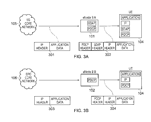
Figures 3A and 3B show protocols and corresponding PDU formats used in the
architectures shown in
Figures 2A and 2B respectively. It will be appreciated that the embodiments
described herein may apply
in scenarios where additional protocols, which are not shown in Figures 3A and
3B, are used; for
example, radio interface protocols such as a radio link control (RLC)
protocol, a medium access control
(MAC) protocol and physical layer protocols may be used to provide the radio
interface between the
eNodeB and the UE. Protocols that operate above the IP protocol layer, such as
a user datagram protocol
(UDP), a transmission control protocol (TCP) and a hypertext transfer protocol
(HTTP), may also be
used. Transport protocols such as those that operate between the core network
and the eNodeB may also
be used.
Figure 3A shows an IP packet 301 which is received from the 5G core network
105 by the eNodeB 101.
The IP packet 301 is associated with a protocol data unit (PDU) session (not
shown), and a QoS flow,
such as one of the QoS flows 201, 202, 203 of Figure 2A. The PDU session may
comprise multiple QoS
flows and, in the example of Figure 3A, the QoS flows 201, 202, 203 may all be
associated with (that is,
CA 03061416 2019-10-24
WO 2018/202545 5
PCT/EP2018/060754
form a part of) the same PDU session. In order to provide the mapping between
multiple QoS flows and a
single radio bearer as described above, a service data adaptation protocol
(SDAP) protocol is used by the
eNodeB 101 and UE 104. Packets, such as packet 302, transmitted by the eNodeB
to the UE include a
corresponding header generated according to the SDAP protocol. In addition,
the packet 302 is generated
in accordance with the PDCP protocol, and includes a header generated by the
PDCP protocol. Although
Figure 3A shows only a single SDAP entity and a single PDCP entity at each of
the UE and the eNodeB,
there may be multiple SDAP entities and/or multiple PDCP entities. In
particular, there may be one pair
of SDAP entities (a pair comprising an entity at the UE and a peer entity at
the eNodeB) associated with a
PDU session and one pair of PDCP entities for each radio bearer. For example,
referring to Figure 2A,
DRB 204 may have an associated PDCP entity and an associated SDAP entity at
the eNodeB and an
associated PDCP entity and an associated SDAP entity at the UE. In some
instances, SDAP is used only
where multiple QoS flows are mapped to a single radio bearer.
In contrast, as shown in Figure 3B, an IP packet 303 received by the eNodeB
from the EPC core network
106 is processed according to a PDCP protocol and accordingly, a packet 304
transmitted by the eNodeB
to the UE includes a PDCP header. Since SDAP is not used for IP packets
received from the EPC core
network, there is no SDAP header included in the packet 304. Although Figure
3B shows only a single
PDCP entity at each of the UE and the eNodeB, there may be multiple PDCP
entities ¨ in particular, there
may be one pair of PDCP entities for each radio bearer.
The term 'protocol entity' as used herein is used to illustrate the various
processing steps carried out by
an eNodeB or a UE. That is, the existence of an entity of a protocol implies
that processing is carried out
on certain data either to be transmitted or received, in accordance with the
specifications of that protocol.
The protocol may, for example, specify the addition or removal of header
information, data compression
or decompression, the maintenance of state information based on the
transmission or reception of data or
other functions as will be known to the skilled person. Protocol entities may
be logically arranged within
an entity such as the UE 104 or the eNodeBs 101,102 to process the data
sequentially according to a
defined sequence, for example in accordance with a layered protocol model such
as the well-known OSI
protocol model.
Example Embodiments
The problems that are addressed by the embodiments of the present technique
relate to the different
architectures used and different set of protocols used by the eNodeB's 101,
102 and their respective core
networks 105, 106. Embodiments of the present technique address technical
problems in the handover
preparation phase which arise as a result of the possibility of mapping
multiple QoS flows to a single data
radio bearer according to a 5G network architecture, while no corresponding
mapping is possible in the
EPC architecture. As shown in Figures 3B and Figure 2B, the mapping between
EPS bearer and radio
bearer is on a one-to-one basis. Further embodiments of the present technique
address the data
forwarding step shown in 403 and 404 of Figure 4 (described below) in light of
the architectural
differences described above.
Figure 4 illustrates a handover procedure in which embodiments of the present
technique may be
applicable. The UE 104 is initially served by a cell controlled by the eNodeB
101 which is connected to
the 5G core network 105. As such, the UE 104 has established one or more QoS
flows, which it receives
over one or more radio bearers from the eNodeB 101. After the handover, the UE
104 is served by a cell
controlled by the eNodeB 102 which is connected to the EPC core network 106.
At some point (not shown in Figure 4), the eNodeB 101 determines that it is
appropriate for the UE to be
transferred to the control of the eNodeB 102. This may be based on handover
criteria being met. This
determination may be based on measurement reports received from the UE or on
signal strength
CA 03061416 2019-10-24
WO 2018/202545 6
PCT/EP2018/060754
measurements or signal quality measurements made by the eNodeB in respect of
signals received from
the UE or based on a current load of the eNodeB 101 or on any other
appropriate factors.
In some embodiments, the source eNodeB 101 and the target eNodeB 102 may be
the same eNodeB (e.g.
they may be eNodeB 103), having connections to both the 5G core network 105
and the EPC network
106. In some such embodiments, the eNodeB may control multiple cells, and the
handover may be
between different cells which are controlled by the same eNodeB; in other such
embodiments, the
handover may be an intra-cell handover; that is, the source and target cells
may be the same.
In response to the determining that the handover criteria are met, a handover
preparation phase 401 is
initiated by the eNodeB 101. As part of the handover preparation phase, the
eNodeB 101 may determine
capabilities of the target eNodeB 102, such as whether it is connected to an
EPC network or a 5G core
network (or both). The eNodeB 101 may also determine (for example, based on
the determined
connectivity of eNodeB 102) whether the handover must be initiated via the 5G
core network, by means
of signalling between the eNodeB 101 and the 5G core network 105, or whether
the handover may be
initiated directly with the eNodeB 102, such as by means of an interface
connecting the two eNodeBs
directly.
The eNodeB 101 transmits a request (either directly, or via the 5G core
network 105) to the eNodeB 102
informing the eNodeB 102 that it considers handover criteria to have been met
in respect of the UE 104,
and in respect of a target cell which is under the control of the eNodeB 102.
In some embodiments, the source eNodeB does not determine an identity of the
target eNodeB, but may
rely on a routing functionality within the 5G core network and/or the EPC
network to route messages
appropriately based on, for example, a globally unique cell identifier
associated with the target cell.
The eNodeB 102 reserves radio resources for the use of the UE 104 in the
target cell and confirms to the
eNodeB 101 that it is able to accept the handover of UE 104. A description of
the reserved radio
resources may be included in a signalling message sent from the eNodeB 102 to
the eNodeB 101, for
onward transmission to the UE 104. In some embodiments of the present
technique, the description of the
reserved radio resources includes a mapping of radio bearers to EPS bearers.
In some embodiments it may
indicate (explicitly or implicitly) that packets that would have been
associated with the QoS flows that are
active in the source cell (such as the flows 201, 202 and 203 of Figure 2A)
will all be carried over a single
EPS bearer, such as the EPS bearer 207 in Figure 2B. Alternatively, a
different mapping may be
indicated explicitly.
As will be appreciated, the handover preparation phase 401 may include other
steps and other signalling.
Subsequent to the handover preparation phase, handover execution then occurs
at step 402. In this step
the UE 104 is commanded to change its serving cell and to connect to the
target eNodeB 102. As a result,
it obtains service (i.e. data connectivity) via the EPC 106 and eNodeB 102 in
the target cell. At this point
in some embodiments, the UE 104 uses one or more of the EPS bearers configured
for the use of the UE
104 in the target cell, and uses an EPS bearer to DRB (one-to-one) mapping, in
place of the QoS flow to
DRB mapping that was in use in the source cell.
It is desirable that no packets are lost as a result of this handover
procedure; that is, that all IP packets
destined for the UE, whether received at the 5G core network 105 or at the EPC
network 106, are
ultimately delivered to the UE. It may be the case that IP packets are
received by the eNodeB 101 from
the 5G core network 105 but are never transmitted to the UE 104 by eNodeB 101
because, for example,
the eNodeB 101 does not have an opportunity to transmit these IP packets
before the UE changes its
serving cell as part of the handover execution phase 402. Alternatively it may
be that an IP packet
CA 03061416 2019-10-24
WO 2018/202545 7
PCT/EP2018/060754
received from the 5G core network by eNodeB 101 was transmitted to the UE 104
but was not
successfully received by the UE. The eNodeB 101 may identify this situation by
the lack of receipt of a
positive acknowledgement of the IP packet from the UE 104.
To mitigate these scenarios, packets may be transmitted by the source eNodeB
101 to the target eNodeB
102 as shown in step 403 for onward transmission in step 404 to the UE 104. In
some embodiments, the
data forwarding steps 403 and 404 form a part of the handover execution phase
402. For clarity in the
following descriptions, they are described as being separate from the handover
execution phase 402;
however, this is not intended to limit the scope of the techniques described
herein to exclude
embodiments in which data forwarding (such as data forwarding steps 403 and
404) is considered part of
the handover execution phase (such as the execution phase 402).
Preparation Phase
Figure 5 illustrates an example embodiment of the present technique, in which
the UE 104 is connected to
the source eNodeB 101 which is an eNodeB controlling an LTE cell and which is
connected to the 5G
core network 105.
In step 501 the eNodeB which is controlling the UE determines that handover
criteria are met in respect
of a target cell controlled by eNodeB 102.
In response to determining that the handover criteria are met, the eNodeB 101
determines that it is
appropriate to notify the 5G core network that the handover has been triggered
by means of a signalling
message such as message 502. According to embodiments of the present
technique, the eNodeB 101
determines that the target cell is controlled by an eNodeB (such as the eNodeB
104) which is connected
to an EPC network such as EPC network 106. Responsive to this determination,
the notification 502 to
the 5G core network 105 may include a handover type indication of "5GC to
EPC". More generally, the
notification 502 may include a handover type information element indicative
that, although the source and
target radio technologies may be both the same (e.g. both based on LTE), the
core networks by which the
connectivity for the UE 104 is to be achieved after handover is different from
the core network by which
connectivity is to be achieved prior to the handover. For example, the
notification 502 may indicate that
the current core network is the 5G core network 105, and that the second core
network will be the EPC
network 106.
In other embodiments not shown in the figures, a notification from an eNodeB
which is connected to an
EPC network may indicate to the EPC network that the handover corresponds to a
type whereby the first
(current) core network is an EPC core network, and the second (target) will be
an 5G core network.
Notifying the 5G core network that the target cell is EPC connected may ensure
that the 5G core network
is able to direct further signaling in respect of the handover preparation
phase towards the appropriate
EPC core network and may be used by the 5G core network to perform any
necessary mapping between
QoS flows in the 5G core network and EPS bearers in the EPC core network.
According to other example embodiments, the eNodeB 101 also transmits to the
5G core network
equipment a representation of its mapping table 206 which indicates the
correspondence between data
radio bearers, such as DRBs 204 and 205, by which the source eNodeB 101
communicates with the UE
104, and end-to-end QoS flows, such as QoS flows 201, 202, 203, by which IP
packets are transferred
from the 5G core network 105 to the UE 104. This is indicated in step 503.
Steps 503 and 502 may
comprise the transmission of two separate messages or may be combined in a
single message.
CA 03061416 2019-10-24
WO 2018/202545 8
PCT/EP2018/060754
In addition, the source eNodeB 101 may include in a message containing
indications 502 and/or 503 a
transparent container which is an information element constructed by the
eNodeB 101 to be passed to the
target eNodeB 102 having been transmitted transparently via the core networks
105, 106.
A benefit of this example embodiment is that a source eNodeB (such as eNodeB
101) does not need to be
aware of a QoS flow to EPS bearer mapping that will be used when the handover
is carried out. In such
an embodiment the necessary mapping between the QoS flows and EPS bearer is
performed after the
handover by the 5G core network.
Figure 6 shows an alternative embodiment of the present technique. In step
601, the eNodeB 101
receives from the 5G core network 105 an indication of a mapping that will be
used between EPS bearers
and QoS flows should a handover occur. This may occur as part of an
establishment procedure for the
QoS flows. The process then proceeds with step 501 and step 502 as already
described above.
The eNodeB 101 constructs an EPS configuration indication 603 by combining the
EPS bearer to QoS
flow mapping received in step 601 with the QoS flow to DRB mapping table 206.
In some embodiments,
the resulting indication comprises an EPS bearer to DRB mapping. In some
embodiments this may result
in an EPS configuration indication 603 which can be understood by the target
eNodeB 102 even if the
eNodeB 102 is not a 5G-aware eNodeB - that is to say, has not been upgraded to
support functionality
associated with interworking with 5G core networks. In some embodiments, the
EPS configuration
indication 603 comprises a QoS flow to EPS bearer mapping associated with a
DRB configuration that is
in use by the source eNodeB 101
In step 602, the eNodeB 101 transmits to the 5G core network 105 a transparent
container for onward
transmission to the target eNodeB 102 containing the EPS configuration
indication 603.
eNodeB 102 may receive the transparent container in message 604, which may be
a Handover Request
message.
A benefit of this embodiment is that it may be used in the case of an X2 based
handover in which the
transparent container containing the EPS configuration indication 603 may be
sent directly from source
eNodeB 101 to target eNodeB 102 without passing through the core networks 105,
106.
Figure 7 shows an alternative embodiment of the present technique. In the
embodiment of Figure 7, the
process starts as in Figure 5 with steps 501 and 502. In step 704, the eNodeB
101 sends a message to the
5G core network including a transparent container which includes a data radio
bearer (DRB) to QoS
mapping indication 701. This may be a representation of table 206. The target
eNodeB 102 may receive
the transparent container in a message 705, which may be a Handover Request
message. Based on the
indication 701, eNodeB 102 maps QoS flows used in the 5G core network 105
(such as the QoS flows
201, 202, 203) to EPS bearers (such as the EPS bearer 207) used in the EPC
network 106, and hence
determines an appropriate data radio bearers for each of the IP packets which
are associated with the
respective QoS flows.
In some embodiments, 5G core network 105 provides a QoS flow to EPS bearer
mapping (which may be
substantially the same as the information described above in step 601 of
Figure 6) to the EPC network
106. In some embodiments, the EPC network 106 provides the QoS flow to EPS
bearer mapping to the
target eNodeB 102, and the target eNodeB 102 performs the mapping of the QoS
flows and radio bearers
indicated in indication 701 to the corresponding EPS bearers based on the QoS
flow to EPS bearer
mapping received from EPC core network 106.
In some embodiments, the target eNodeB 102 determines that a full
configuration handover is required.
This determination may be based on the determination that the target eNodeB
102 is unable to parse the
CA 03061416 2019-10-24
WO 2018/202545 9
PCT/EP2018/060754
transparent container received from the eNodeB 101. For example (as shown in
step 702) it may
determine that that critical information which it expects to receive in a
transparent container (e.g. in
accordance with a specification) is missing. In one example, it may determine
a full configuration
handover is to be performed based on an absence of an identifier of an EPS
bearer in a transparent
.. container (such as the transparent container containing indication 701)
received from the source eNodeB
101. In a further example, the target eNodeB 102 determines that a full
configuration is required if a
security algorithm in use in the source cell is not supported in the target
cell (e.g. because it is not
supported by the EPC core network 106).
The determination to perform a full configuration handover may be based on
predetermined conditions
comprising one or more of the above.
In some embodiments a determination to perform a full configuration handover
by the eNodeB 102
precludes a determination that the handover is considered to have failed, as
may be done in a
conventional approach.
Responsive to this determination, initiates a full configuration handover in
which resources in a target
cell are reserved and associated with an EPS bearer, without reference to, for
example, data radio bearers
used for corresponding EPS bearers or QoS flows in a previous cell. According
to some embodiments in
which a full configuration handover is performed, after the handover execution
phase the UE 104
discards, or operates without reference to, any PDCP protocol state
information stored while operating in
the source cell, regardless of whether a radio bearer corresponding to the
respective PDCP protocol entity
.. is operating in an acknowledged mode or in an unacknowledged mode.
According to some embodiments in which a full configuration handover is
performed, the target eNodeB
102 constructs a handover command message which is transmitted in a
transparent container, such as the
transparent container 708 indicated by a dashed line in Figure 7, to the UE
104 which includes a
description of the radio resources reserved in the target cell without
reference to the configuration of the
radio resources which are assigned to the UE 104 by the source eNodeB 101 for
use by the UE 104 in the
source cell. In some embodiments in which a full configuration handover is
performed, the description of
the radio resources includes an indication of the correspondence between
reserved radio resources and
one or more EPS bearers.
The transparent container 708 containing the handover command is transported
from the target eNodeB
102 to the UE 104 by means of messages 703, 706, 707 sent via the core
networks 105, 106 and the
source eNodeB 101. (Messages carrying the transparent container within or
between the core networks
105, 106 are not shown).
After receiving the transparent container 708, in some embodiments the UE 104
may determine that an
identity of a core network bearer (such as an identity of the QoS flows 201,
202, 203) which is active in
the source cell is not present in the handover command. Responsive to this
determination, the UE 104
nevertheless proceeds with the handover. In particular, the UE 104 does not
determine that the handover
message is erroneous. In some embodiments, the UE 104 further determines that
the handover message is
not erroneous, based on a presence of the identity of a bearer (such as the
identity of the EPS bearer 207)
of the type corresponding to the core network technology (e.g. 5G, EPC)
associated with the target cell.
According to some embodiments in which a full configuration handover is
performed, the handover
command message describes radio resources which are associated with one or
more EPS bearers for use
in the target cell. However, the UE 104, when operating in the source cell and
connected to the source
eNodeB 101, associated IP packets with one or more QoS flows. Therefore, in
some embodiments, the
UE 104, based on a combination of a QoS flow to EPS bearer mapping and the
previous QoS flow
CA 03061416 2019-10-24
WO 2018/202545 10
PCT/EP2018/060754
description, determines which EPS bearer (and therefore which radio bearer and
corresponding radio
resources) in the target cell to associate with an IP packet which is to be
transmitted in the target cell to
the target eNodeB 102. The UE 104 transmits the IP packet to the target eNodeB
102 in accordance with
this determination. In some embodiments, the UE receives a representation of
the QoS flow to EPS
bearer mapping either prior to or during a handover preparation phase (such as
the handover preparation
phase 401).
The embodiment shown in Figure 7 has the benefit that it does not require the
eNodeB 101 to have
received the EPS bearer to QoS flow mapping and it further simplifies the
operation of the eNodeB 101
because the indication 701 sent in the transparent container is information
that it has readily available
without requiring any further mapping.
In the embodiments described above, one or more of the indications transmitted
from the source eNodeB
to the 5G core network (such as messages 502, 503, 602, 704) may be
transmitted in a Handover
Required message.
The transparent containers 603, 701 may be forwarded from the source eNodeB
101 to the target eNodeB
104 via the 5G core network 105 and the EPC network 106. The transparent
container may contain an
RRC Handover preparation information element, which may be in conformance with
an RRC
HandoverPreparationInformation information element defined in 3GPP TS 36.331.
The transparent containers 603, 701 may be transmitted directly from the
source eNodeB 101 to the target
eNodeB 104 via an interface (such as an X2 interface) between the eNodeBs
which does not require the
transparent container to traverse a core network. The transparent container in
this case may be sent in a
Handover Request message.
Data Forwarding
Figure 8 is a message flow diagram illustrating aspects of an embodiment of
the technique which
addresses the problem of forwarding data from the source eNodeB 101 to the
target eNodeB 102 to
ensure reliable delivery of all IP data packets.
The process starts with IP packets such as IP packet 301 being transmitted
from the 5G core network to
the eNodeB 101, where they are associated ¨ as illustrated in Figure 2A ¨ with
a QoS flow such as QoS
flow 201. These messages are then processed according to the SDAP protocol and
PDCP protocol in the
eNodeB 101 as illustrated in Figure 3A and are transmitted to UE 104 as data
packets such as the data
packet 302 which includes the IP packet together with an SDAP header and a
PDCP header.
The details of the handover preparation phase and the handover execution phase
have broadly been
described above and are omitted here for conciseness.
Once the handover execution phase is complete, the UE 104 is no longer served
by the source eNodeB
101 and any IP packets which remain stored at the eNodeB 101, which have not
been positively
acknowledged as having been received by UE 104, must be forwarded to eNodeB
102. As described
above, in accordance with embodiments described herein, the forwarding of IP
packets may be carried out
after the handover execution phase (as illustrated in Figures 8, 9, and 10) or
as part of the handover
execution phase.
In the embodiment illustrated in Figure 8, the eNodeB 101 may have already
associated a PDCP sequence
number with an IP packet received from the 5G core network 105. The eNodeB 101
may, in addition,
have already constructed a data packet for transmission to the UE 104 which
includes both an SDAP
header and a PDCP header. In the embodiment of Figure 8, the PDCP header and
the SDAP header are
CA 03061416 2019-10-24
WO 2018/202545 11
PCT/EP2018/060754
removed, if they have been already constructed, and the IP packet is forwarded
together with the PDCP
sequence number in message 803 from the source eNodeB 101 to the target eNodeB
102.
The message 803 may be transmitted directly from the eNodeB 101 to the eNodeB
102, for example, by
means of an X2 interface, or it may be transmitted indirectly via the
respective core networks 105, 106.
The eNodeB 102 processes the forwarded IP packet according to the PDCP
protocol, based on the PDCP
sequence number received from the source eNodeB 101. It then forwards the IP
packet complete with a
PDCP header to the UE in message 804.
As will be appreciated, this corresponds to the format used for transmission
of IP packet 304 in Figure
3B; that is to say, the format of the data transmitted from eNodeB 102 to the
UE complies with the format
that would be expected for packets received directly from the EPC network,
such as IP packet 805 which
is transmitted to the UE in transmission 806.
The embodiment shown in Figure 8 therefore has the advantage that no
additional functionality is
required in target eNodeB 102 above and beyond that which is already required
in respect of handovers
from other EPC-connected eNodeBs.
In some embodiments, the UE 104 releases its SDAP entity at the point at which
handover execution
occurs; in other words, at the point at which it expects to no longer receive
packets which have been
processed by the SDAP entity of the source eNodeB 101. In some further
embodiments, the inclusion of
the PDCP sequence number in message 803 is optional. In further embodiments
the PDCP sequence
number is omitted for all transmissions 803.
In some embodiments, the source eNodeB 101 determines whether a full
configuration handover has been
performed. In some embodiments the source eNodeB 101 may determine whether the
number of PDCP
entities associated with the UE 104 will be the same in the target eNodeB 102
after the handover
execution as it is in the source eNodeB 101.
If the source eNodeB 101 determines that full configuration handover has been
performed, or if the
.. source eNodeB 101 determines that the number of PDCP entities associated
with the UE 104 will not be
the same in the target eNodeB 102 as it is in the source eNodeB 101, the
source eNodeB forwards IP
packets to the target eNodeB, with no associated PDCP sequence number and
without any SDAP or
PDCP headers.
In some embodiments, the source eNodeB 101 determines on a packet-by-packet
basis whether or not a
PDCP sequence number has been assigned to a particular packet such as the
packet 301. If no sequence
number has been assigned, the source eNodeB forwards the IP packet to the
target eNodeB 102, with no
associated PDCP sequence number or SDAP or PDCP headers.
In some embodiments, if the source eNodeB determines that a full configuration
handover has not been
performed, and that the number of PDCP entities associated with the UE 104
will be the same in the
target eNodeB 102 as it is in the source eNodeB 101, and that a PDCP sequence
number has been
assigned to a particular packet, then the packet is forwarded, together with
the PDCP sequence number
and, in some embodiments, together with an SDAP header.
Figure 9 illustrates a further embodiment of the present technique. In Figure
9, the messages 301 and 302
are as already described above. In the embodiment shown in Figure 9, once the
eNodeB 101 identifies
that it has a packet to be forwarded to the target eNodeB 102 the packet is
forwarded as shown at step
901, formatted to include the IP packet and an SDAP header and sent together
with a PDCP sequence
number. No PDCP header is included in the transmission 901. In this
embodiment, a representation of
the mapping between the QoS flows and the EPS bearers is received by the
target eNodeB 102 (not
CA 03061416 2019-10-24
WO 2018/202545 12
PCT/EP2018/060754
shown in Figure 9), and this information is used to map each packet received
from source eNodeB 101 to
an appropriate radio bearer (such as the radio bearer 209) that has been
established between the target
eNodeB 102 and the UE 104. Based on the mapping, and taking into account the
SDAP header
associated with the transmission 901, the target eNodeB 102 associates the IP
packet and the PDCP
sequence number with an appropriate PDCP entity which is currently in
operation and which has a peer
corresponding entity at the UE 104.
The eNodeB 102 removes the SDAP header from the packet received in
transmission 901 and attaches an
appropriate PDCP header in a transmission 902 to the UE 104.
In the example shown in Figure 9 the processing, whereby the QoS flow to EPS
bearer mapping is made
use of to process forwarded packets (such as the packet in 901), is shown as
being co-located with the
target eNodeB 102. However, this functionality may exist elsewhere in the
network as a separate entity.
As with the embodiment illustrated in Figure 8, this approach has the benefit
that a packet received by the
UE 104 once it is in the target cell conforms to the protocols used in an EPC-
connected cell as illustrated
in Figure 3B. This approach also has the advantage that packets which are
created in eNodeB 101 for
transmission to the UE can be forwarded with minimal further processing to
eNodeB 102 thereby
simplifying the implementation of eNodeB 101.
Figure 10 illustrates yet a further embodiment of the present technique. In
Figure 10, an IP packet such as
IP packet 301 is forwarded to UE in a message 302 which includes an SDAP
header and a PDCP header.
After handover execution, the eNodeB 101, determining that it has a packet
which may not have been
correctly received by the UE either because it was never transmitted to the UE
or because it was
transmitted to the UE but not acknowledged, forwards the packet to eNodeB 102.
In the embodiment illustrated in Figure 10, the packet is formatted so as to
be understood by the target
eNodeB 102 as comprising a PDCP service data unit (SDU) together with a PDCP
sequence number. As
such, the message 1001 as received by the eNodeB 102 appears to the eNodeB 102
as a message
compliant with conventional data forwarding messages used between LTE eNodeBs.
However, in this case the PDCP SDU portion includes, as well an IP packet, an
SDAP header which has
been added by an SDAP protocol entity of the source eNodeB 101. The forwarded
packet does not
include a PDCP header.
The eNodeB 102 processes the received message 1001 as if it were a forwarded
LTE message comprising
a PDCP SDU and an associated sequence number and constructs a PDCP header
based on the PDCP
sequence number. The PDCP header is attached to the PDCP SDU and forwarded to
the UE 104 in step
1002.
Not shown in Figure 10, the UE 104 receiving the message 1002 processes the
received message
according to the PDCP protocol and determines that the PDCP SDU contained in
the message 1002
includes an SDAP header which was generated by the source eNodeB 101. Having
determined that the
PDCP SDU includes an SDAP header, the UE 104 processes the message in
accordance with the SDAP
protocol. In the embodiment illustrated in Figure 10, the UE 104 therefore
maintains its SDAP entity
(which was established in the source cell prior to handover) after the UE 104
has changed its serving cell.
In some embodiments, the UE 104 removes its SDAP entity based on a
determination that no further
packets are likely to be received which include an SDAP header. This
determination may be based on
signalling, such as radio resource control (RRC) signalling, received from
target eNodeB 102.
Alternatively, the determination may be made responsive to the expiry of a
timer which is started during
the handover execution step. The duration of the timer may be according to a
specification, or may be
CA 03061416 2019-10-24
WO 2018/202545 13
PCT/EP2018/060754
configured by the network, for example in an RRC reconfiguration message
transmitted by either the
source eNodeB 101 or the target eNodeB 102.
The eNodeB 102 may receive a packet directly from the EPC such as the IP
packet 1003. This is
processed in the conventional manner by generating a PDCP header in accordance
with the PDCP
protocol, and is forwarded as shown in step 1004 to the UE 104, compliant with
the format illustrated in
304 of Figure 3B.
As an alternative to the sequence shown in Figure 10, the eNodeB A 101 may
have an IP packet for
which no PDCP sequence number has yet been determined. In some embodiments,
this may be
forwarded directly to the target eNodeB 102 without a PDCP sequence number and
without an SDAP
header. The target eNodeB 102 assigns a PDCP sequence number and constructs
the PDCP header and
forwards the resulting message to UE 104.
This approach, as illustrated in Figure 10, has the benefit that the target
eNodeB 102 does not need to be
upgraded to be able to process forwarded messages which include an SDAP
header. Even though such
messages are received by the target eNodeB 102 (such as message 1001), the
target eNodeB 102
processes these in accordance with conventional procedures for the receipt of
forwarded packets which
comprise a PDCP SDU and are associated with a PDCP sequence number.
In some embodiments the UE 104 may, on receipt of a message transmitted from
the target eNodeB 102
following a handover, make a determination as to whether or not the received
message includes an SDAP
header and, responsive to that determination, process the received message
accordingly. In the case where
it determines that the SDAP header is included, it removes the SDAP header
before passing the IP packet
to higher protocol layers. In the case where the message is determined not to
include an SDAP header, the
UE 104 processes that in accordance the conventional approach for packets
received from the target
eNodeB 102 which have been transmitted to the eNodeB 102 by the EPC core
network 106 such as
packets 1003 and 1004.
In another example embodiment, the source eNodeB 101 determines that a packet
has not been
successfully transmitted to the UE 104 and determines a corresponding sequence
number according to a
transport protocol used between the eNodeB 101 and 5G core network. The
transport protocol may be a
General Packet Radio Service (GPRS) Tunnelling Protocol (GTP) protocol and the
sequence number may
be a GTP sequence number. The source eNodeB 101 then indicates to the 5G core
network 105 one of i)
the sequence number(s) of packet(s) which have not been transmitted to the UE
and ii) the sequence
number of the last GTP packet (that is, the GTP packet with the highest
sequence number) that has been
transmitted to the UE 104. This indication may be communicated to the 5G core
network 105 by means
of a signalling message (which may be a GTP control protocol data unit or an
51 message sent on an 51
control plane) or by means of a last transmitted sequence number header field
in a GTP packet which is
transmitted from the source eNodeB 101 to the 5G core network 105.
Based on this message, the 5G core network 105 forwards the relevant packets
to the EPC for onward
forwarding to the target eNodeB 102 and the UE 104 in the target cell.
In addition, in some embodiments a control plane entity in one of the core
networks 105, 106 (which may
be a mobility management entity, MME, or an AMF) transmits an indication of
the sequence number(s)
of GTP packets for which data forwarding is required to a serving gateway (S-
GW) or entity performing
similar functionality.
As will be appreciated by the skilled person, various combinations of the
embodiments described above
are possible. For example, with reference to Figure 4, embodiments described
above which relate to the
CA 03061416 2019-10-24
WO 2018/202545 14
PCT/EP2018/060754
handover preparation phase 401 may be combined with embodiments described
above which relate to
data forwarding steps 403 and 404 and the corresponding processing of data.
Various aspects and features of the present technique are defined in the
appended claims. Various
modifications may be made to the example embodiments as disclosed above as
appreciated by the skilled
person within the scope of the appended claims. Various further example
embodiments and features are
defined in the following numbered paragraphs:
Paragraph 1. A method performed in a first infrastructure equipment for a
handover of a wireless
communications device from the first infrastructure equipment as a source to a
second infrastructure
equipment as a target, the method comprising
maintaining a mapping between a plurality of packet bearers and a data radio
bearer for the
wireless communications device, each of the plurality of packet bearers being
configured to provide a
specified quality of service,
determining that the wireless communications device should handover from the
first
infrastructure equipment to the second infrastructure equipment,
determining that the second infrastructure equipment does not support the
mapping of the
plurality of packet bearers to the data radio bearer, and
providing an indication of a mapping of the plurality of packet bearers for
the second
infrastructure equipment after handover to one of a core network equipment and
the second infrastructure
equipment for configuration of at least one of the radio bearer and the
plurality of packet bearers at the
second infrastructure equipment after the handover.
Paragraph 2. A method according to paragraph 1, wherein the providing an
indication of a mapping of
the plurality of packet bearers for the second infrastructure equipment after
handover includes
providing an indication of the mapping between the plurality of packet bearers
and the data radio
bearer for the wireless communications device maintained by the first
infrastructure device.
Paragraph 3. A method according to paragraph 1, the method comprising:
receiving from the core network equipment an indication of a mapping of the
plurality of packet
bearers to one or more packet bearers for the second infrastructure equipment
after handover, and
wherein the providing an indication of a mapping of the plurality of packet
bearers for the second
infrastructure equipment after handover includes
providing an indication of the mapping from the plurality of packet bearers to
the one or more
packet bearers for the second infrastructure equipment after handover.
Paragraph 4. A method according to any of paragraphs 1 to 3, wherein the
providing the indication of
the required mapping of the plurality of packet bearers to a corresponding
plurality of data radio bearers
for the second infrastructure equipment after handover includes
generating a signalling message for transmission to the core network equipment
to which the first
infrastructure equipment is connected, the signalling message indicating that
the second infrastructure
equipment does not support the mapping of the plurality of packet bearers to
the data radio bearer, and
sending the signalling message to the core network equipment in preparation
for the handover.
Paragraph 5. A method according to paragraph 4 wherein the signalling message
provides an
indication of the mapping of a plurality of radio bearers to the plurality of
packet bearers for configuring
the second infrastructure equipment via an interface between the second
infrastructure equipment and a
second core network to which the second infrastructure equipment is connected.
Paragraph 6. A method according to paragraphs 1 or 2, wherein the providing
the indication of the
mapping of the plurality of packet bearers for the second infrastructure
equipment after handover includes
generating a transparent container for transmission to the second
infrastructure equipment, the
transparent container including a representation of the mapping, and
transmitting the transparent container to the second infrastructure equipment.
CA 03061416 2019-10-24
WO 2018/202545 15
PCT/EP2018/060754
Paragraph 7. A method according to paragraph 4, wherein the transparent
container is transmitted to
the second infrastructure equipment from the first infrastructure equipment
via an interface between the
first infrastructure equipment and the second infrastructure equipment.
Paragraph 8. A method performed in a first infrastructure equipment not
supporting a mapping of a
plurality of packet bearers to a data radio bearer for a handover of a
wireless communications device from
a second infrastructure equipment as a source to the first infrastructure
equipment as a target, the method
comprising
receiving a request for the handover of the wireless communication device,
receiving an indication of a mapping of a plurality of packet bearers for
configuration of at least
one of a radio bearer and a plurality of packet bearers after the handover,
configuring a radio bearer for the wireless communications device based on the
indication of the
mapping of the plurality of packet bearers,
generating a message indicating the configuration of the reserved radio bearer
for transmission to
the wireless communication device.
Paragraph 9. A method of paragraph 8, wherein the message indicating the
configuration of the
reserved radio bearer for transmission to the wireless communication device
includes a mapping between
the radio bearer and a packet bearer.
Paragraph 10. A method of paragraph 8 or paragraph 9, wherein the message
indicating the
configuration of the reserved radio bearer for transmission to the wireless
communication device includes
a mapping between the radio bearer and at least one of the plurality of packet
bearers.
Paragraph 11. A method of paragraph 9, wherein the mapping between the radio
bearer and at least one
of the plurality of packet bearers is a mapping of all of the plurality of
packet bearers to the radio bearer.
Paragraph 12. A method of any of paragraphs 8 to 11 wherein the indication of
a mapping of a plurality
of packet bearers for configuration of at least one of a radio bearer and a
plurality of packet bearers after
the handover is received in a transparent container generated by the second
infrastructure equipment.
Paragraph 13. A method of paragraph 12, comprising
determining that the transparent container does not comply with one or more
predetermined
requirements, and
responsive to the determination, configuring the radio bearer without regards
to a configuration of
a radio bearer by the second infrastructure equipment.
Paragraph 14. An infrastructure equipment forming a radio network part of a
wireless communications
network, configured to transmit data to and/or receive data from a wireless
communications device, and
to transmit the data to or receive the data from a core network part of the
wireless communications
network, the infrastructure equipment comprising
receiver circuitry configured to receive radio signals transmitted by the
wireless communications
device via a wireless access interface,
transmitter circuitry configured to transmit radio signals to the wireless
communications device
via the wireless access interface, and
controller circuitry configured to control the transmitter circuitry and the
receiver circuitry to
transmit data to or receive data from the wireless communications device and
to transmit the data to or
receive the data from the core network via an interface with the core network,
wherein the controller
circuitry is configured to
to maintain a mapping between a plurality of packet bearers and a data radio
bearer for the
wireless communications device, each of the plurality of packet bearers being
configured to provide a
specified quality of service,
to determine that the wireless communications device should handover from the
first
infrastructure equipment to a second infrastructure equipment,
CA 03061416 2019-10-24
WO 2018/202545 16
PCT/EP2018/060754
to determine that the second infrastructure equipment does not support the
mapping of the
plurality of packet bearers to the data radio bearer, and the controller is
configured in combination with
the transmitter circuitry
to transmit an indication of a mapping of the plurality of packet bearers for
the second
infrastructure equipment after handover to the core network equipment for
configuration of at least one of
the radio bearer and the plurality of packet bearers at the second
infrastructure equipment after the
handover.
Paragraph 15. An infrastructure equipment forming a radio network part of a
wireless communications
network, configured to transmit data to and/or receive data from a wireless
communications device, and
to transmit the data to or receive the data from a core network part of the
wireless communications
network, the infrastructure equipment comprising
receiver circuitry configured to receive radio signals transmitted by the
wireless communications
device via a wireless access interface,
transmitter circuitry configured to transmit radio signals to the wireless
communications device
via the wireless access interface, and
controller circuitry configured to control the transmitter circuitry and the
receiver circuitry to
transmit data to or receive data from the wireless communications device and
to transmit the data to or
receive the data from the core network via an interface with the core network,
wherein the controller
circuitry is configured
to receive a request for a handover of the wireless communication device,
to receive an indication of a mapping of a plurality of packet bearers for
configuration of at least
one of a radio bearer and a plurality of packet bearers after the handover,
to configure a radio bearer for the wireless communications device based on
the indication of the
mapping of the plurality of packet bearers and
to generate a message indicating the configuration of the reserved radio
bearer for transmission to
the wireless communication device,
wherein the infrastructure equipment does not support a mapping of a plurality
of packet bearers
to a data radio bearer.
Paragraph 16. A method for forwarding data received by a first infrastructure
equipment acting as a
source to a second infrastructure equipment acting as a target for a wireless
communications device
during handover, the method comprising:
receiving first data for transmission to the wireless communications device
from a core network
to which the first infrastructure equipment is connected,
generating a first protocol data unit according to a first protocol, the
protocol data unit including
the received first data and a first protocol header,
determining that the wireless communications device has performed the
handover,
in response to determining that the wireless device has performed the
handover, transmitting the
received first data to a second infrastructure equipment for transmission to
the wireless communications
device
wherein the first protocol provides a mapping of a plurality of packet
bearers, configured to
provide a specified quality of service, to a data radio bearer.
Paragraph 17. A method according to paragraph 16, further comprising
determining a sequence number in accordance with a second protocol,
generating a second protocol data unit in accordance with the second protocol,
the second
protocol data unit including the first protocol data unit and the sequence
number,
transmitting the second protocol data unit to the wireless communications
device.
Paragraph 18. A method according to paragraph 16, comprising
determining a sequence number in accordance with a second protocol,
transmitting the sequence number to the second infrastructure equipment.
CA 03061416 2019-10-24
WO 2018/202545 17
PCT/EP2018/060754
Paragraph 19. A method according to paragraph 16, comprising
determining a sequence number in accordance with a second protocol,
wherein transmitting the received data to a second infrastructure equipment
for transmission to
the wireless device comprises transmitting the first protocol data unit
together with the sequence number
to the second infrastructure equipment.
Paragraph 20. A method according to any of paragraphs 16 to 19, comprising
receiving second data for transmission to a wireless communications device
from a core network,
generating a third protocol data unit according to the first protocol, the
third protocol data unit
including the received second data and a header in accordance with the first
protocol,
generating a fourth protocol data unit in accordance with the second protocol,
the fourth protocol
data unit including the third protocol data unit and a sequence number in
accordance with the second
protocol,
before determining that the wireless communications device has performed a
handover,
transmitting the second protocol data unit to the wireless communications
device.
Paragraph 21. An infrastructure equipment forming a radio network part of a
wireless communications
network, configured to transmit data to and/or receive data from a wireless
communications device, and
to transmit the data to or receive the data from a core network part of the
wireless communications
network, the infrastructure equipment comprising
receiver circuitry configured to receive radio signals transmitted by the
wireless communications
device via a wireless access interface,
transmitter circuitry configured to transmit radio signals to the wireless
communications device
via the wireless access interface, and
controller circuitry configured to control the transmitter circuitry and the
receiver circuitry to
transmit data to or receive data from the wireless communications device and
to transmit the data to or
receive the data from the core network via an interface with the core network,
wherein the controller
circuitry is configured
to receive first data for transmission to the wireless communications device
from the core
network equipment,
to generate a first protocol data unit according to a first protocol, the
protocol data unit including
the received first data and a first protocol header,
to determine that the wireless communications device has performed the
handover, and
in response to determining that the wireless device has performed the
handover, to transmit the
received first data to a second infrastructure equipment for transmission to
the wireless communications
device,
and the first protocol provides a mapping of a plurality of packet bearers,
configured to provide a
specified quality of service, to a data radio bearer.
Paragraph 22. A method for transmitting data to a wireless device by a second
infrastructure equipment
acting as a target after handover from a first infrastructure equipment acting
as a source, the method
comprising
receiving data for transmission to the wireless communications device, the
data including a first
portion comprising a header according to a first protocol, a second portion
comprising a header according
to a second protocol, and a third portion,
receiving a sequence number associated with the data according to the second
protocol,
transmitting the third portion to the wireless communications device,
wherein the data is received from the first infrastructure device.
Paragraph 23 An infrastructure equipment forming a radio network part of a
wireless communications
network, configured to transmit data to and/or receive data from a wireless
communications device, and
to transmit the data to or receive the data from a core network part of the
wireless communications
network, the infrastructure equipment comprising
CA 03061416 2019-10-24
WO 2018/202545 18
PCT/EP2018/060754
receiver circuitry configured to receive radio signals transmitted by the
wireless communications
device via a wireless access interface,
transmitter circuitry configured to transmit radio signals to the wireless
communications device
via the wireless access interface, and
controller circuitry configured to control the transmitter circuitry and the
receiver circuitry to
transmit data to or receive data from the wireless communications device and
to transmit the data to or
receive the data from the core network via an interface with the core network,
wherein the controller
circuitry is configured
to receive data for transmission to the wireless communications device, the
data including a first
portion comprising a header according to a first protocol, a second portion
comprising a header according
to a second protocol, and a third portion,
to receive a sequence number associated with the data according to the second
protocol, and the
controller is configured to transmit the third portion to the wireless
communications device, and the data
is received from source infrastructure equipment of the radio network part of
the wireless
communications network.
Paragraph 24. A method of receiving data by a wireless communications device
in a wireless network
during handover from a first infrastructure equipment acting as a source to a
second infrastructure
equipment acting as a target, the method comprising:
receiving by the wireless communications device first data in a first network
cell from a first
infrastructure equipment, the first data comprising a first data portion
received by the first infrastructure
equipment from a first core network and a first protocol header in accordance
with a first protocol and a
second protocol header in accordance with a second protocol, the second
protocol header including a
sequence number, the first and second protocol headers being generated by the
first infrastructure
equipment,
performing a handover to a second cell associated with a second infrastructure
equipment, the
second infrastructure equipment connected to a second core network different
from the first core network,
receiving a second data in the second network cell, the second data comprising
a second data
portion,
determining whether the second data includes a third protocol header in
accordance with the first
protocol;
if the second data includes the third protocol header in accordance with the
first protocol,
removing the third protocol header before processing the second data in
accordance with the second
protocol;
receiving third data in the second network cell, the third data comprising a
third data portion
received by the second infrastructure equipment from the second core network
and a header in accordance
with the second protocol, the second protocol header including a sequence
number generated by the
second infrastructure equipment.
25. A method according to paragraph 24, wherein the second
infrastructure equipment is an eNodeB
connected to an enhanced packet core, EPC, network and the receiving the
second data includes receiving
the second data from the second infrastructure equipment, which has been
received from a 5G core
network.
Paragraph 26. A method according to paragraph 24 or 25, wherein the second
protocol is associated
with a radio bearer and provides one or more of header compression, security,
and retransmission of the
second data.
Paragraph 27. A method according to paragraph 26, wherein the second protocol
is a packet data
convergence protocol (PDCP).
Paragraph 28. A method according to paragraph 24, wherein the receiving the
second data includes
receiving the second data from the second infrastructure equipment, which has
been received by the
CA 03061416 2019-10-24
WO 2018/202545 19
PCT/EP2018/060754
second infrastructure equipment via an interface between the first
infrastructure equipment and the second
infrastructure equipment.
Paragraph 29. A method according to paragraph 24, wherein the receiving by the
wireless
communications device the first data in the first network cell from a first
infrastructure equipment
includes receiving the first data from the first core network using an
internet protocol, IP, packet.
Paragraph 30. A method according to any of paragraphs 24 to 29, wherein the
first protocol provides a
mapping of a plurality of packet bearers, configured to provide a specified
quality of service, to a data
radio bearer.
Paragraph 31. A communications device configured to transmit radio signals to
and/or receive radio
signals from a first infrastructure equipment and a second infrastructure
equipment of a wireless
communications network, the communications device comprising
a receiver circuit configured to receive radio signals transmitted by the
first and second
infrastructure equipment via a wireless access interface,
a transmitter circuit configured to transmit radio signals to the first and
second infrastructure
equipment via the wireless access interface, and
a controller circuit configured to control the transmitter circuit and the
receiver circuit to transmit
data to or receive data from the wireless communications network via the first
and second infrastructure
equipment, wherein the controller circuit is configured to control the
receiver circuit
to receive first data in a first network cell from the first infrastructure
equipment, the first data
comprising a first data portion received by the first infrastructure equipment
from a first core network and
a first protocol header in accordance with a first protocol and a second
protocol header in accordance with
a second protocol, the second protocol header including a sequence number, the
first and second protocol
headers being generated by the first infrastructure equipment,
to perform a handover to a second cell associated with the second
infrastructure equipment, the
second infrastructure equipment connected to a second core network different
from the first core network,
to receive a second data in the second network cell, the second data
comprising a second data
portion, the controller configured
to determine whether the second data includes a third protocol header in
accordance with the first
protocol, and,
if the second data includes the third protocol header in accordance with the
first protocol, to
remove the third protocol header before processing the second data in
accordance with the second
protocol; and the controller circuit is configured to control the receiver
circuit
to receive third data in the second network cell, the third data comprising a
third data portion
received by the second infrastructure equipment from the second core network
and a header in accordance
with the second protocol, the second protocol header including a sequence
number generated by the
second infrastructure equipment.
Paragraph 32. A communications device according to paragraph 31, wherein the
second infrastructure
equipment is an eNodeB connected to an enhanced packet core, EPC, network and
the second data has
been received by the second infrastructure equipment from a 5G core network.
Paragraph 33. A communications device according to paragraph 31 or 32, wherein
the second protocol
is associated with a radio bearer and provides one or more of header
compression, security, and
retransmission of the second data.
Paragraph 34. A communications device according to paragraph 33, wherein the
second protocol is a
packet data convergence protocol (PDCP).
Paragraph 35. A communications device according to paragraph 31, wherein the
second data has been
received by the second infrastructure equipment via an interface between the
first infrastructure
equipment and the second infrastructure equipment.
Paragraph 36. A communications device according to paragraph 31, wherein the
first data comprises an
internet protocol, IP, packet.
CA 03061416 2019-10-24
WO 2018/202545 20
PCT/EP2018/060754
Paragraph 37. A communications device according to any of paragraphs 31 to 36,
wherein the first
protocol provides a mapping of a plurality of packet bearers, configured to
provide a specified quality of
service, to a data radio bearer.
References
[1] LTE for UMTS: OFDMA and SC-FDMA Based Radio Access, Harris Holma and
Antti Toskala,
Wiley 2009, ISBN 978-0-470-99401-6.
[2] 3GPP TS 36.331
[3] 3GPP TS 38.300