Note: Descriptions are shown in the official language in which they were submitted.
FRICTION STIR WELDING FLASH REMOVAL COMPONENT
TECHNICAL FIELD
[0001] The present disclosure is directed towards a component for a friction
stir welding (FSW)
head that facilitates flash removal.
BACKGROUND
[0002] Friction stir welding (FSW) is a welding process that uses heat
generated from high-
pressure friction to form a joint between two workpieces and/or to fix cracks
in a workpiece.
That is, during FSW operations, an FSW tool traverses a joint or seam disposed
between the
workpieces (or a crack in a workpiece) and the one or more workpieces are
plasticized by
frictional heat generated by rotation of the FSW tool. As the FSW tool
traverses the seam, the
FSW tool is also pressed against the one or more workpieces. More
specifically, during a
welding operation, a shoulder is pressed against the workpiece(s) and a pin
rotates in the seam
between the workpieces (or in a crack in a workpiece). In some FSW heads, the
shoulder rotates
with or relative to the pin, but in other FSW heads, the shoulder may be
stationary. Rotation of
the pin (and the shoulder in some instances), softens and mixes the materials
forming the
workpieces. Then, the mixed materials consolidate to form a solid-state weld.
[0003] An FSW tool (which may include the pin and the shoulder) can traverse a
seam (or crack)
when its FSW head moves relative to the workpiece(s) and/or when the
workpiece(s) are moved
relative to the welding tool (e.g., the welding tool may be stationary).
Regardless, as a FSW tool
welds a seam, the friction between the FSW tool and the workpiece(s), the
softening of the
workpieces(s) causes at least some material to be extruded away from the
workpieces as "flash."
1
CA 3061550 2019-11-13
,
s_.
For example, often, a circumferential collar of extruded material rolls back
from the FSW tool to
form a configuration resembling a ram's horn, which is commonly referred to as
a bifurcated
flash formation. Consequently, to finish a FSW weld, the flash must be removed
from the
workpiece(s).
[0004] Often, the flash is removed with milling or grinding processes that
traverse the seam after
the FSW tool. For example, after welding a seam, a FSW tool can be removed
from a rotary
machine and replaced with a milling tool so that the rotary machine can remove
the flash during
a second pass over the weld. Alternatively, a user can mill the flash with a
milling tool that is
separate and distinct from the FSW machine. However, each of these options
lengthens the takt
time (e.g., the rate of production) for a particular job. Still further, some
FSW welding heads
have incorporated blades that can remove (e.g., cut) flash from a weld seam as
the FSW welding
head traverses the seam; however, often these blades scatter chips (i.e.,
pieces of flash)
throughout the workplace. Not only does this scattering of chips create a
mess, but also in some
instances, the chips may enter the FSW machine and force an end-user to clean
the machine.
Alternatively, the chips might adhere to a part of the weld seam that has yet
to full coalesce,
negating the blade's attempt to remove the flash from the seam.
SUMMARY
[0005] The present disclosure is directed towards a friction stir welding
(FSW) flash removal
unit and FSW heads including the same. According to one embodiment, the FSW
flash removal
unit includes a blade and an annular body. The blade removes flash created by
a FSW tool
during FSW operations. The annular body defines a flash capture area around
the blade and is
configured to at least temporarily retain the flash removed by the blade
within the flash capture
2
CA 3061550 2019-11-13
,
area. Advantageously, since the annular body retains the flash in the flash
capture area, removed
flash is not scattered across workpiece, workshop, and/or back into a weld
seam from which it
was removed.
[0006] In at least some of these embodiments, the annular body is an annular
brushing unit and
the flash removal unit includes an annular cutting unit that includes the
blade. In these
embodiments, the annular brushing unit is disposed radially exterior of the
annular cutting unit.
In at least some of these embodiments, the blade extends along at least a
portion of an inner edge
of the annular cutting unit so that the blade is at least partially annular.
For example, the portion
of the inner edge may be a portion aligned with a trailing edge of the FSW
operations. This may
ensure that the blade extends across or spans a plasticized region created
during FSW operations
and, thus, may ensure that the blade removes flash generated at any location
of the plasticized
region. In some embodiments, the blade is stationary with respect to the FSW
head and is
positioned to shave a top of a plasticized region created during the FSW
operations.
Advantageously, a stationary blade will not scatter flash as it detaches the
flash from a welding
seam (i.e., a plasticized region), especially as compared to blades that
rotate with an FSW tool.
[0007] In some embodiments of the FSW flash removal unit, the flash removal
unit includes a
brush that is longitudinally aligned with the blade and configured to at least
temporarily retain
the flash removed by the blade within the flash capture area. The brush may be
compressible
against a workpiece and, thus, may act to form a seal or seal-type enclosure
with the workpiece
that encloses the flash capture area. However, the brush may also be air
permeable so that the
flash removal unit can be operatively coupled to a vacuum unit that can remove
detached flash
from the flash removal unit with suction. In fact, in some embodiments, the
flash removal unit
includes a flow path that extends through the annular body and guides the
flash removed by the
3
CA 3061550 2019-11-13
s,
blade away from the flash capture area. In some instances, a vacuum unit may
be attached to the
flow path to provide the aforementioned suction. In at least some embodiments,
the blade is
included in a cutting unit that defines one or more first openings and the
annular body defines
one or more second openings. The one or more first openings and the one or
more second
openings define the flow path.
[0008] According to another embodiment, a cutting unit suitable for a FSW head
is presented
herein. The cutting unit includes an annular body and a partially annular
blade. The annular
body has a top and a bottom. The bottom has an inner edge and an outer edge.
The partially
annular blade extends around at least a portion of the inner edge of the
bottom of the annular
body and the annular body is fixed to the FSW head so that the partially
annular blade is
stationary with respect to the FSW head during FSW operations of the FSW head.
Additionally,
the annular body is fixed to the FSW head so that the blade is positioned to
trail a FSW tool
included in the FSW head and cut flash created by the FSW tool during FSW
operations off of a
weld seam. As mentioned, a stationary blade offers advantages over rotating
blades at least
because it does not create a mess of scattered chips that need to be cleaned
from the workshop,
the machine, and potentially the weld seam.
[0009] In at least some of these embodiments, the annular body includes one or
more openings
configured to guide the flash cut off of the weld seam away from the weld
seam. Due to these
openings, the cutting unit may direct removed flash to a specific location so
that, for example,
the flash may be collected by a vacuum unit. Consequently, the openings may
further ease
cleanup after FSW operations. Additionally or alternatively, the partially
annular blade may
extends around the entire inner edge. If the blade extends around the entire
inner edge, a FSW
4
CA 3061550 2019-11-13
machine may continue FSW operations in any direction without rearranging or
reorienting the
cutting unit. The cutting unit will cut flash no matter the direction of the
FSW operations.
100101 According to yet another embodiment, a FSW head is provided herein. The
FSW head
includes a head housing, an axle, and an annular flash removal unit. The head
housing extends
from a top end to a bottom end. The axle is coaxial with and rotatable within
the head housing.
The axle also includes an end portion that extends beyond the head housing and
supports an
FSW tool. The annular flash removal unit removes flash created by the FSW tool
during FSW
operations of the FSW head. Additionally, the annular flash removal unit
defines a flash capture
area around the FSW tool and at least temporarily retains removed flash within
the flash capture
area. Thus, the FSW head advantageously removes flash during FSW operations
while
preventing or reducing the amount of flash scattered across workpiece,
workshop, and/or weld
seam. Moreover, and also advantageously, the FSW head may be a stationary
shoulder FSW
head or a rotating shoulder FSW head.
BRIEF DESCRIPTION OF THE DRAWINGS
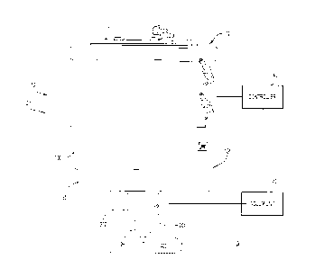
[0011] FIG. IA is a side view of a friction stir welding (FSW) head with a
representation of a
flash removal unit according to an example embodiment of the present
disclosure, the FSW head
being disposed in a first configuration.
[0012] FIG. 1B is a bottom perspective view of the FSW head of FIG. 1A while
disposed in a
second configuration and including a representation of a flash removal unit
formed in accordance
with another example embodiment of the present disclosure included thereon.
[0013] FIG. 2 is a sectional view of the FSW head of FIG. I B.
CA 3061550 2019-11-13
1 =
[0014] FIG. 3A is a bottom perspective view of a flash removal unit installed
on an engagement
end of the FSW head of FIG. 1B, the flash removal unit being formed in
accordance with an
example embodiment of the present disclosure.
[0015] FIG. 3B is a front perspective view of the flash removal unit of FIG.
3A, but with a brush
unit included in the flash removal unit removed.
[0016] FIG. 4 is a front sectional view of a portion of the flash removal unit
of FIG. 3A installed
on the engagement end of the FSW head of FIG. 1B.
[0017] FIGs. 5A-5E provide a perspective view, a side view, a bottom view, a
front sectional
view, and a back view, respectively, of a cutting unit included in the flash
removal unit of FIG.
3A.
[0018] FIGs. 6A and 6B provide a top perspective view and a sectional view,
respectively, of
another example embodiment of a cutting unit suitable for the flash removal
unit of FIG. 3A.
[0019] FIGs. 7A and 7B provide a bottom perspective view and a top perspective
view,
respectively, of a brush unit included in the flash removal unit of FIG. 3A.
[0020] FIG. 8 is a sectional view of a portion of the flash removal unit of
FIG. 3A while installed
on the FSW head of FIG. 1B during FSW operations.
[0021] Like numerals identify like components throughout the figures.
6
CA 3061550 2019-11-13
,
DETAILED DESCRIPTION
[0022] A friction stir welding (FSW) component that can be included in or
coupled to a FSW
head and facilitates flash removal is presented herein. Generally, the FSW
component is a flash
removal unit and includes a cutting unit and a brush unit. The cutting unit
includes a blade that
is configured to remove or detach flash from a welding seam and/or workpiece
and the brushing
unit is configured to retain the detached flash within a boundary defined by a
perimeter of the
flash removal unit. That is, the cutting unit and the brushing unit are each
annular components
and are configured to remove and retain flash within a central opening defined
by their annuli.
Moreover, the cutting unit and the brushing unit collectively define a
passageway that can be
operatively coupled to a vacuum unit so that any detached flash removed and
retained by the
flash removal unit can be neatly removed from the FSW head and the workpiece
with suction.
[0023] Thus, advantageously, the flash removal unit presented herein removes
flash without
creating a mess of chips scattered over/in the workpiece, the FSW seam, and/or
the FSW
machine. By comparison, a single blade that rotates around a FSW head to
remove flash may
scatter chips of flash (also referred to herein simply as chips, detached
flash, removed flash, or
variations thereof) around a workspace, along a workpiece, and into a machine.
This scattering
of chips may negate any efficiencies allegedly created by the blade (e.g.,
efficiencies associated
with removing flash while welding) since a user will be required to perform
extensive cleanup of
the FSW machine, the workpiece, and/or the workspace after completing FSW
operations with a
rotating blade. Alternatively, if an end user eschews does not use a rotating
blade, the end user
will be required to perform additional machining after completing FSW
operations to finish the
FSW seam. For example, the end user may need to grind or mill the FSW seam to
remove flash.
7
CA 3061550 2019-11-13
i
Not only is the additional machining timely and inefficient, but it may also
be more difficult to
remove flash after a FSW seam has cooled and hardened, which may cause a user
to exert more
force on, and possibly damage, the seam during the additional machining.
[0024] FIGs. IA and 1B illustrate an example FSW head 10 that can accommodate
the flash
removal unit 400 presented herein while in a rotating shoulder configuration
Cl (see FIG. 1A) or
a stationary shoulder configuration C2 (see FIG. 1B). In order to clearly show
the FSW head 10,
FIGs. 1A and 1B illustrate the FSW head 10 with a representation of a flash
removal unit 400
installed thereon and the flash removal unit is shown in further detail in the
subsequent figures.
Notably, the welding head 100 can be transitioned between the rotating
shoulder configuration
Cl and the stationary shoulder configuration C2 by adding or removing a bell
housing 300 to a
bottom of the FSW welding head 100. Otherwise, the FSW head 10 is largely the
same in both
configuration Cl and configuration C2.
100251 Although the FSW head 10 shown in FIGs. 1 A in 1B is shown primarily to
illustrate an
example FSW head that can support the flash removal unit 400 (also referred to
as a flash
removal accessory 400 or flash removal component 400) presented herein, the
FSW head 10 is
now described in at least some detail in order to provide a full understanding
of the flash removal
component 400. However, the description of FSW head 10 is in no way intended
to limit the
scope of the flash removal component 400 presented herein and it is to be
understood that the
flash removal component 400 can be installed on any FSW head now known or
developed
hereafter. Moreover, the description included below of FSW head 10 is
relatively brief and
focused on operations of FSW head 10 that are relevant to the flash removal
component 400 at
least because the FSW head 10 depicted in the Figures is described in detail
(without the flash
removal accessory 400) in U.S. Patent Application No. 15/941.092, filed on
March 30, 2018, and
8
CA 3061550 2019-11-13
entitled "Welding Head for Friction Stir Welding," which is hereby
incorporated by reference in
its entirety.
100261 That all being said, the FSW head 10 illustrated in FIGs. IA and 1B
includes a head
housing 100 and an axle 202. The head housing 100 extends from a first or top
end 102 to a
second or bottom end 104. The top end 102 can be attached to a robot, gantry,
or other such
holding structure. Meanwhile, the bottom end 104 provides an opening that can
receive an axle
202. The axle 202 is coaxial with a central axis of the housing 100 and
extends through a bore
defined by the housing 100 in an axial or longitudinal direction so that a
portion 204 of the axle
202 extends beneath the bottom end 104 of the housing 100. An FSW tool 280
that defines a
shoulder and pin/probe during FSW is coupled to portion 204 of the axle 202
(which may also be
referred to as bottom end 204, welding end 204, or engagement end 204).
10027] In this application, portion 204 of axle 202, the tool 280 installed
therein, and the bell
housing 300 may be collectively referred to as the engagement or welding
portion 30 of the FSW
head 10. The welding portion 30 is described in further detail below; however,
generally, the
flash removal accessory 400 presented herein is installed or included on/over
the welding portion
30 of the FSW head 10. For example, when the FSW head 10 is in the rotating
shoulder
configuration Cl, the flash removal unit 400 is installed onto and over the
FSW tool 280 and the
portion 204 of axle 202 that protrudes below the bottom end 104 of housing (as
illustrated at a
high-level in FIG. 1A). Meanwhile, when the FSW head 10 is in the stationary
shoulder
configuration C2, the flash removal unit 400 is installed or included
onto/over the FSW tool 280,
the portion 204 of axle 202 that protrudes below the bottom end 104, and the
bell housing 300
(as is illustrated at a high-level in FIGs. 1B and 2). In at least some
embodiments, the FSW head
9
CA 3061550 2019-11-13
may include a mount 290 (see FIGs. 1B and 3A) that helps to align the welding
portion 30
with a central, longitudinal axis of the head housing 100.
[0028] Before or subsequent to installing the flash removal unit 400 on the
FSW head 10, the
flash removal unit 400 can be connected to a vacuum unit 42 that can provide
suction for the
flash removal unit 400. The vacuum unit may also include or define a bag,
canister, dust bag,
cyclone, and/or any such receptacle that can capture chips of detached flash
that are suctioned
out of the flash removal unit 400 (similar to a household vacuum).
Alternatively, the flash
removal unit might include an on-board vacuum unit that can provide suction
and capture chips
of detached flash. As is described in further detail below, suction, whether
from an external
vacuum unit, like vacuum unit 42, or an on-board vacuum unit, allows the flash
removal unit 400
to capture and remove flash that it detaches from a weld seam the FSW head 10
creates. In some
embodiments, the vacuum unit 42 may be controlled by a controller 40 that is
controlling
operations of the FSW head (as is described below) so that, for example, the
vacuum unit 42 is
powered on when the FSW head 10 is powered on.
[0029] Still referring to FIGs. 1A and 1B, but now with reference to FIG. 2 as
well, in the
depicted embodiments, an annular load cell 250 is also positioned beneath the
bottom end 104,
so that the load cell 250 is adjacent or proximate the engagement end 204 of
the axle (and the
tool 280). Generally, the load cell 250 generates load signals as a function
of forces exerted on
the engagement end 204 of the axle 202 (by way of the tool 280). In other
words, and as is
explained in further detail in U.S. Patent Application No. 15/941,092, which,
as mentioned
above, is incorporated by reference in its entirety, as the tool 280 acts
against a workpiece, the
axle 202 will move slightly upwards with respect to the housing 100, pushing
or pulling a
CA 3061550 2019-11-13
portion of the load cell 250 so that the load cell 250 generates load signals
as a function of the
longitudinal forces exerted on the bottom end 204 of the axle 202 (by way of
the tool 280).
100301 To effectuate this, the FSW head 100 may include a connector ring 220
that couples an
inner ring 252 of the load cell 250 to the axle 202 (e.g., via other
components included in FSW
head 100). On the other hand, the inner ring 252 is also flexibly coupled, via
a flexible portion
254, to the outer ring 256 of the load cell, which is fixedly coupled to the
head housing 100.
Thus, any axial movement of the axle may cause the load cell 250 to generate
load signals due to
the relative movement of the inner ring 252 with respect to the outer ring
256. The signals may
be sent to controller 40 via signal path 258 so that the controller 40 can
control operations of the
FSW head 10.
100311 For example, upon receiving load signals, the controller 40 may convert
the load signals
into force measurements (e.g., digital data) that can be used to control the
FSW operations and
ensure a high-quality weld. That is, the controller may accumulate data from
the load signals
and determine whether the downward force applied to the FSW head needs to be
altered, for
example, to ensure complete penetration with the FSW tool 280. Force
measurements can be
taken continuously and are used to maintain the force at a desired level
throughout the welding
process to produce a smooth surface and desired characteristics of the weld.
Depending on the
requirements of a particular welding process or workpiece, the target force
level can be
programmed to vary during sections of a weld. Further, the force measured
throughout a
welding process can be recorded (e.g., the force can be recorded on a time
basis or as a function
of the position of the welding head relative to the workpiece). Optionally,
controller 40 can be
configured to generate a visual or aural warning in the event the force
deviates from a target
force level.
11
CA 3061550 2019-11-13
,
,
[0032] Still referring to FIGs. IA, 1B, and 2, overall, the depicted welding
head 10 is compact
and does not require external forces (e.g., from a spindle drive/actuator,
etc.). That is, the
welding head 10 has relatively small external dimensions and may be a
relatively self-contained
FSW head, insofar as the head may operate without an external drive mechanism
(but may still
need to be coupled to a power source, controller, and/or a holding device,
such as a gantry). As
an example of the external dimensions of the welding head 10, the welding head
100 may have
an external diameter in the range of approximately 100 mm to approximately 500
mm and an
external longitudinal dimension (e.g., a height) in the range of approximately
200 mm to
approximately 1,000 mm. As one specific example, for a typical welding
thickness up to 12 mm,
the welding head 100 may have an external diameter of approximately 250 mm and
an external
longitudinal dimension (e.g., a height) of approximately 325 mm.
[0033] This compact design reduces deviation (bend) created on a holding
structure (robot,
gantry, etc.) and also minimizes the chances of the head 10 colliding with
portions of the
workpiece, portions of a holding structure, or other such objects during FSW
operations.
Consequently, the FSW head depicted in FIGs. lA and 1B may be suitable, if not
preferable, for
supporting the flash removal unit 400 supported herein. That is, the FSW head
10 depicted in
FIGs. 1A and 113 may reduce or eliminate deflection issues that have sometimes
caused annular
cutting blades to be problematic. However, in other embodiments, the flash
removal unit
presented herein can also be used with, incorporated into, or included in FSW
welding heads of
any shape or size that operate in any manner now known or developed hereafter
to effectuate
FSW operations.
[0034] Now turning to FIG. 2, although the flash removal accessory provided
herein can be used
with a myriad of FSW heads, for completeness, FIG. 2 depicts a sectional view
the welding head
12
CA 3061550 2019-11-13
t
shown in FIG. I B. The sectional view depicts the axle 202 in its entirety, a
motor 150 that is
configured to rotate the axle 202 about a central axis and various bearings
that facilitate this
rotation. More specifically, the axle 202 is a rotatable body that extends
from (or through) the
top end 102 of the housing 100 to (or through/out of) the bottom end 104 of
the housing 100.
The axle 202 may be substantially cylindrical; however, the axle may also
include various steps,
depressions, receptacles, and other such features that allow the axle to be
secured within the head
housing 100 in manner that prevents the axle 202 from tilting or translating
laterally while also
ensuring that the motor 150 can engage and rotate the axle 150.
[0035] In the depicted embodiment, the motor 150 is a rotational motor 150
with a stator 152
that is fixedly coupled to the head housing 100 and a rotor 154 that is
fixedly coupled to a
portion of the axle 202 disposed between an upper bearing 210 and a lower
bearing 212 (which
is supported by a bearing housing 214). The rotor 154 may be mechanically
spaced from the
lower bearing 212 and the load cell 250 by a radial spacer to ensure that the
rotor 154 does not
become magnetically stuck and/or damaged when the lower bearing 212 is
serviced. Meanwhile,
the stator 152 is fixed to the head housing 100 and can be liquid cooled via
inlets/outlets formed
in the housing 100. Generally, the motor 150 may impart rotational motion to
the axle 202 (and,
thus, to the tool 280).
[0036] The axle 202 may include an internal bore or passage 206. The passage
206 is
configured to align with cooling features included in the tool 280 and with
coolant delivery
features included in the head housing 100. Additionally, a lower end of the
axle 202 may
include an axial cavity sized to receive a body of the tool 280. The cavity
may have any
desirable size and may also include a locking feature (not shown), such as a
threaded screw, that
allows any desirable tool 280 to be secured to the axle 202. The tool 280
protrudes (e.g.. extends
13
CA 3061550 2019-11-13
,
downwards) from the lower end 204 of axle 202 and defines a shoulder 284 and a
pin or probe
282 (see FIG. 4) that will create a joint in or between one or more
workpieces. In the depicted
embodiment, the shoulder 284 has a truncated conical shape; however, in other
embodiments, the
operating end of the tool 280 may have any desirable shape and/or include any
desirable features
(e.g., the pin may include threads). Moreover, in other embodiments, the pin
282 may be
movable with respect to the shoulder 284 (e.g., retractable) and/or include
any other FSW
features now known or developed hereafter.
[0037] Now turning to FIGs. 3A, 3B, and 4, these Figures depict the flash
removal unit 400 that
is shown as a dashed box representation in FIGs. 1A, 1B, and 2. At a high-
level, the flash
removal unit includes a cutting unit 410 and a brushing unit 430. The cutting
unit 410 is
disposed radially interiorly of the brushing unit 430 and, thus, in FIG. 3A,
the cutting unit 410 is
largely obscured. In FIG. 3B, the brushing unit 430 is removed to show the
exterior of the
cutting unit 410. In the depicted embodiment, the cutting unit 410 has a
cylindrical exterior that
engages and extends around a bottom 302 of the bell housing 300. Meanwhile,
the brushing unit
has a cylindrical exterior that engages and extends around an outer diameter
of a midsection 310
of the bell housing 300.
[0038] However, in other embodiments, the cutting unit 410 and the brushing
unit 430 may have
any exterior shape and size. For example, in some embodiments, the flash
removal unit 400 may
be sized and shaped to match the shape of a stationary shoulder 300, a
rotating shoulder 284,
and/or a welding surface. As a specific example, in some embodiments, the
flash removal unit
may be substantially triangular so that the flash removal unit can be used for
corners and/or fillet
welds.
14
CA 3061550 2019-11-13
[0039] Additionally, the cutting unit 410 and the brushing unit 430 can be
coupled to the FSW
head 10 in any manner, provided that the coupling prevents translation of the
flash removal unit
400 in at least the X-direction and the Y-direction with respect to the FSW
head 10 (e.g., along
the bottom face of the welding head 10). In the depicted embodiment, the
cutting unit 410 and
the brushing unit 430 are coupled to the bell housing 300 (e.g., with
fasteners) and, thus are
stationary during FSW operations. That is, when the axle 202 is rotated by the
motor 150, the
bell housing 300 and the flash removal unit 400 will not rotate. Put still
another way, the
depicted flash removal unit 400 is fixed in all six degrees of freedom with
respect to the FSW
head 10 (and, thus, moves with the head 10 if, for example, a gantry or arm
moves or rotates the
FSW head 10).
[0040] However, in other embodiments, the flash removal unit 400 may be height
adjustable
with respect to the FSW head and, thus, may only be fixed in five degrees of
freedom with
respect to the FSW head 10 (X translation, Y translation, and all three
degrees of rotation). That
is, in some embodiments, the flash removal unit 400 may be adjustable along a
Z-axis (i.e., a
longitudinal axis) of the FSW head 10. Additionally or alternatively, in at
least some
embodiments, the cutting unit 410 and/or the brushing unit 430 may be coupled
to another
portion of the FSW head 10 (e.g., the head housing 100 or a top portion 320 of
the bell housing
300) that fixes the cutting unit 410 and/or the brushing unit 430 with respect
to the axle 202.
[0041] In other embodiments, the cutting unit 410 and/or the brushing unit 430
can be directly or
indirectly coupled to the axle 202 so that at least a portion of the flash
removal unit 400 rotates
with or with respect to the axle 204. For example, when the flash removal unit
is included with
or installed onto the FSW head 10 in its rotating shoulder configuration Cl
(see FIG. 1A), the
cutting unit 410 may be coupled to the axle 202 and the brushing unit 430 may
be coupled to the
CA 3061550 2019-11-13
lower end 102 of the housing 100. As other examples, both the cutting unit 410
and the brushing
unit 430 may be coupled to the axle 202 (and rotate therewith) or both the
cutting unit 410 and
the brushing unit 430 may be coupled to the lower end 102 of the housing 100
(to remain
stationary as the axle 202 rotates).
[0042] Still further, in some embodiments, the flash removal unit 400, or at
least a portion
thereof, may be coupled to the axle 202 via a gear assembly or other such
mechanical
components so that the flash removal unit 400 (or a portion thereof) rotates
when the axle 202
rotates, but at a different speed and/or in a different direction. More
generally, the flash removal
unit 400 can be coupled to any type of FSW head, including bobbin-type FSW
heads, stationary
shoulder FSW heads, and rotating shoulder FSW heads, in any manner. In fact,
the flash
removal unit 400 may be particular useful for rotating shoulder FSW heads
since a rotating
shoulder typically leaves rotation tracks in the weld seam and the flash
removal unit 400 can
clean those tracks.
[0043] Regardless of its exterior shape and size, as well as the manner in
which it is coupled to
the FSW head 10, the brushing unit 430 of the flash removal unit 400 is
annular so that the
brushing unit defines a bounded or enclosed flash capture area "FA." That is,
since the brushing
unit 430 is annular, a periphery of the flash capture area FA is bounded by or
enclosed by the
brushing unit 430. In at least some embodiments, the cutting unit 410 is also
annular; however,
the cutting unit 410 need not be annular. Instead, the cutting unit 410 is
either disposed within
the flash capture area FA so that flash removed from a welding seam by the
cutting unit 410 is
removed in the flash capture area FA or otherwise configured to introduce
detached flash chips
into the flash capture area FA. For example, the cutting unit might be a
stationary blade that
16
CA 3061550 2019-11-13
,
,
extends across a diameter of the flash capture area FA in a direction that is
perpendicular to
welding direction of a FSW machine including the flash removal unit 400.
[0044] In the depicted embodiment, the cutting unit 410 and the brushing unit
430 are both
annular and are also both coaxial with the axle 202 of the welding head 10.
Consequently, the
flash capture area FA is concentric with the cutting unit 410. Thus, when the
flash removal unit
400 removes flash from a welding seam (as is described in detail below in
connection with FIG.
8), the removed/detached flash is encouraged to remain beneath the FSW head 10
and is
substantially prevented from scattering across a workpiece, workstation, etc.
[0045] Now turning to FIGs. 4 and 5A-5E, in the depicted embodiment, the
cutting unit 410
includes an annular main body 411 that extends from a bottom 412 to a top 416
(See FIG. 5A)
while defining a central opening 418. As can be seen best in FIG. 5C, the
bottom 412 has a face
4121 that is defined by an inner edge 4122 and an outer edge 4123. The outer
edge 4123 is a
rounded or chamfered edge. Meanwhile, the inner edge 4122 is a defined corner
(i.e., a right
angle or smaller) and at least a portion of the inner edge 4122 receives or
defines a blade 414.
Moreover, in the depicted embodiment, the bottom face 4121 has a first zone
4125 and a second
zone 4126 that are connected by connectors 4127 (shown best in FIGs. 5B and
SC). The
connectors 4127 may extend gradually away from the first zone 4125, but may
form a hard or
defined edge with the second zone 4126.
[0046] In the depicted embodiment, the second zone 4126 of the bottom 412 is
aligned with an
opening 420 formed in the main body 411 and the blade 414 is included along at
least a portion
of the inner edge 4122 of the second zone 4126. Additionally or alternatively,
the blade may be
formed along the hard edges formed between the second zone 4126 and the
connectors 4127.
17
CA 3061550 2019-11-13
Either way, the blade 414 is arranged so that it can cut any flash away from a
workpiece shortly
after the flash is created by the tool 280 welding the workpiece. That is,
since the blade 414
extends around at least a portion of the inner an inner edge 4122 of the
second zone 4126, the
blade 414 will extend across a plasticized region created by the tool 280 and
remove any flash
created at any point in the plasticized region. Extending the blade 414 along
the hard edges
formed between the second zone 4126 only expands the width or span of the
blade 414 and
further ensures that the blade 414 spans the plasticized region (i.e., spans a
weld seam).
[0047] In some embodiments, the blade 414 may be at least partially formed or
defined by the
main body 411 and, thus, may be the same material as the main body 411,
provided the main
body 411 is formed from a material suitable for cutting flash away from a weld
seam (e.g., the
material has suitable hardness, durability, etc.). Additionally or
alternatively, the blade 414 may
include a secondary element that is added to or included in the main body 411,
such as a
hardened steel coating, a knife element, a saw-tooth member, a diamond edge,
etc. A secondary
element may be included in or attached to the inner edge 4122 of the cutting
unit 410 in any
manner.
[0048] Regardless of how the blade 414 is formed or defined, the blade 414 may
be at least
partially annular, insofar as "partially annular" is intended to denote that
the blade 414 is arcuate
and extends along at least a portion of a circular or ovular edge that defines
the central opening
418 of the cutting unit 410. In at least some embodiments, the partially
annular blade 414 spans
the width or diameter of the cutting unit 410. These dimensions ensure that
the annular blade
414 spans an entire plasticized region created by the FSW tool 280 and, thus,
allow the annular
blade 414 to remain stationary, if desired, during FSW operations. Since a
stationary blade 414
will only be moving as fast as the welding head 10 is moving laterally along a
welding seam, the
18
CA 3061550 2019-11-13
,
stationary blade 414 advantageously minimizes the velocity of the blade 414 as
it cuts, especially
as compared to blades that rotate with an axle and, thus, minimizes the
chances of flash being
scattered over a workpiece, work station, etc.
[0049] That all being said, in other embodiments, the blade 414 may be
included along or extend
between any surfaces of the bottom 412, provided that the blade 414 can remove
flash created
during FSW operations as the FSW head 10 completes the FSW operations. That
is, the blade
414 may be included along or extend between any surfaces of the bottom 412
provided that the
blade 414 trails the FSW tool 280 and spans the plasticized region. For
example, in some
embodiments, the blade 414 may extend along the entire inner edge 4122 of the
bottom 412. In
these embodiments, the FSW tool can weld a seam in any direction without
rearranging or
reorienting the flash removal unit 410. Additionally or alternatively, in
other embodiments, the
bottom 412 of the cutting unit may be entirely flat (i.e., not include any
zone), may include more
than two zones, or may be contoured in any way.
[0050] Still referring to FIGs. 4 and 5A-5E, in the depicted embodiment, the
cutting unit is
substantially hollow and includes an outer wall 4101 and an inner wall 4102
(see FIG. 5D, which
shows, among other items, a wall 4203 extending through a hollow area formed
between inner
wall 4102 and outer wall 4101). As mentioned, the bottom 412 is closed or
solid. Meanwhile,
the top 416 may be open or closed and, overall, the cutting unit 410 can be
hollow, solid, filled,
partially solid, etc. However, regardless of the overall structure of the
cutting unit 410, the main
body 411 also defines at least one circumferential opening 420, insofar as the
word
"circumferential" is used to describe how at least one opening is disposed
on/around a
circumference of the cutting unit 410. In the embodiment depicted in FIGs. 5A-
5E, the cutting
19
CA 3061550 2019-11-13
,
,
unit 420 includes a single opening 420; however, in other embodiments, such as
the embodiment
depicted in FIGs. 6A and 6B, the main body 411 may define a plurality of
openings.
[0051] The opening 420 defines a pathway that extends from the inner wall 4101
to the outer
wall 4102 so that any flash detached from a welding seam by blade 414 can exit
the central
opening 418 of the cutting unit 410. Put another way, the opening 410 provides
a channel
through which detached flash can exit the cutting unit 410. As is discussed in
further detail
below, in the depicted embodiment, suction generated by a vacuum unit 42 (see
FIGs. 1A and
1B) that is operatively coupled to the flash removal unit 400 draws detached
flash out of the
cutting unit 410 and into the brushing unit 430. However, in other
embodiments, the detached
flash need not move be drawn into a brushing unit by suction and, instead, can
simply exit the
cutting unit 410 via the opening 420.
[0052] In order to encourage detached chips of flash to exit the cutting unit
through the opening
420, the opening 420 includes an upwardly sloped bottom wall 4201 and an
upwardly sloped top
wall 4203. Put another way, on the inner wall 4102 the opening 420 is disposed
at a first height
below a fixed horizontal plane (e.g., a horizontal plane aligned with the top
edge 416 of the outer
wall 4101) and, on the outer wall 4101, the opening 420 is disposed a second
distance below the
fixed horizontal plane. The second distance is less than the first distance
and walls 4201 and
4203 connect these longitudinally offset openings. The upwardly sloped walls
4201 and 4203
help to guide detached flash up and away from a welding seam and, thus, help
the flash removal
unit 400 capture flash removed by the cutting unit 410.
[0053] Now turning to FIGs. 6A and 6B, these Figures depict a cutting unit 510
configured in
accordance with a second embodiment. The cutting unit 510 is largely similar
to the cutting unit
CA 3061550 2019-11-13
,
,
410 depicted in FIGs. 5A-5E, except that the cutting unit 510 includes
multiple circumferential
openings 520 spaced around a solid main body 511 and also includes a
substantially flat bottom
512 with an annular blade 514 that extends around an entirety of the inner
edge 5124 of the
bottom 512. For brevity, parts of cutting unit 510 that are similar to parts
of cutting unit 410,
including top 516, central opening 518, upwardly sloping top and bottom walls
5201 and 5203 of
the opening 520, and the overall shape and size of the cutting unit 510, are
not described in detail
and any description of parts of cutting unit 410 included above is to be
understood to apply to the
like parts included in cutting unit 510.
[0054] The multiple openings 520 and the annular blade 514 included in cutting
unit 510 allow a
flash removal unit 400 including the cutting unit 510 to be used continuously
for FSW operations
in any direction without rearranging reorienting the flash removal unit 400.
For example, if
desired, a flash removal unit 400 including the cutting unit 510 could make
multiple passes back
and forth along a seam without rotating the entire FSW machine 180 degrees at
an end of the
seam. By comparison, a flash removal unit 400 including cutting unit 410
and/or a FSW
machine with a flash removal unit 400 including the cutting unit 410 might
need to be reoriented
to keep the opening 420 and blade 414 oriented at a trailing edge of the FSW
operations before
changing the direction of FSW operations executed with that machine.
[0055] That being said, the cutting unit 410 may offer at least some
advantages as compared to
cutting unit 510. For example, it may be cheaper to produce a cutting unit
with fewer
circumferential openings and fewer circumferential openings may allow the
flash removal unit
400 to utilize less (or less complicated) suction since the suction (e.g.,
provided by vacuum unit
42) can draw removed flash along less paths (which are defined by the
openings). Consequently,
the number of openings included in a cutting unit may be determined by
balancing advantages
21
CA 3061550 2019-11-13
,
s
against needs for a particular flash removal unit 400. The size and position
of the blade may also
be determined based on similar considerations and/or based on the number of
openings.
[0056] Now turning to FIGs. 7A and 7B, but with continued reference to FIG. 4,
for a
description of an example brushing unit 430 that may be included in the flash
removal unit 400.
In the depicted embodiment, the brushing unit 430 includes an annular main
body 431 that
extends from a bottom 432 to a top 436 while defining a central opening 438
that defines the
flash capture area FA. The bottom 432 supports a brush 434 that is configured
to retain chips of
detached flash within the flash capture area FA of the flash removal unit 400.
That is, the brush
434 prevents, or at least discourages, detached flash from sliding outside the
periphery of the
flash removal unit 400. The brush 434 also includes or defines airflow
channels so that air can
enter the brushing unit 430 and/or flash capture area FA when suction is
applied to the flash
removal unit (e.g., provided by vacuum unit 42). In at least some embodiments,
the channels
may also allow chips of detached flash to be suctioned into the main body 431
of the brushing
unit 430 through the brush 434.
[0057] The main body 431 also defines a circumferential opening 440 that is
configured to align
with the opening 420 included in cutting unit 410 so that the opening 440 can
guide detached
flash exiting the cutting unit 410 away from the flash removal unit 400
(insofar as the term
"circumferential" is used similar to the manner it is used above, except now
with respect to the
brushing unit 430 instead of the cutting unit 410). The opening 420 extends
through an outer
wall 4401 of the main body 431 and, in the depicted embodiment, is disposed
above an inner
wall 4402 of the main body 431 so that the opening need not extend through the
inner wall 4402.
However, in other embodiments, the opening 420 can extend through any portions
of the main
22
CA 3061550 2019-11-13
body 431, provided that it provides a path or channel from the central opening
438 to an exterior
of the main body 431.
[0058] In the depicted embodiment, the brushing unit 430 includes only a
single opening 440;
however, in other embodiments, the brushing unit 430 may include any number of
openings
(similar to the cutting unit 410). As is discussed in further detail below,
the opening 440 is
positioned to align with the opening 420 included in the cutting unit 410 so
that the opening 440
and opening 420 can define a pathway for detached flash to exit the flash
removal unit 400.
Consequently, if the cutting unit includes a plurality of openings (e.g., as
shown in FIGs. 6A and
6B), the brushing unit 430 may also include a plurality of openings, which may
be positioned to
match or mate with the openings included on the cutting unit 410.
[0059] Alternatively, the brushing unit 430 need not include a pattern of
openings 440 that
matches the openings included on a cutting unit and, instead, may define
radially oriented flow
paths that operatively connect multiple (e.g., all) openings of the cutting
unit to any number (e.g.,
one) of openings 440 included on the brushing unit 440. In the depicted
embodiment, the
brushing unit 440 includes an upwardly sloped surface 4404 (similar to the
upwardly sloped
surfaces 4201 and 4203 included in the cutting unit 410) that connects opening
440 to the central
opening 438 of the brushing unit 430. The sloped surface 4404 also encourages
detached flash
to move up and away from a welding seam when suction is applied to the flash
removal unit 400
(e.g., by vacuum unit 42).
[0060] FIG. 8 depicts an example embodiment of the flash removal unit 400
during FSW
operations. In this example, the flash removal unit 400 is included on the FSW
head 10 while
the FSW head 10 is in its stationary shoulder configuration C2. In this
configuration, the FSW
23
CA 3061550 2019-11-13
head 10 is acting on a workpiece "WP" to generate a weld seam "WS" while
moving in a weld
direction "WD." As mentioned, in the depicted embodiment, the opening 420 in
the cutting unit
410 is aligned with the opening 440 included in the brushing unit 430 at a
trailing edge of the
welding head 10 (e.g., a back of the welding head 10 with respect to the
welding direction
"WD"). Thus, opening 420 and opening 440 collectively define a flow path "FP"
that exits the
flash removal unit 400 at a trailing edge of the welding head 10.
[0061] More specifically, the upwardly sloped walls 4201 and 4203 of opening
420 (together
with sidewalls extending therebetween) extends from a first segment of the
flash capture area FA
that trails the FSW tool 280 to the central opening 438 of the brushing unit,
adjacent the
upwardly sloped wall 4404 of the brushing unit 440. The suction provided by
the vacuum unit,
draws the detached flash up this first segment and then, further draw the
detached flash up a
second segment defined by the upwardly sloped wall 4404 and the opening 440 of
the brushing
unit 440.
[0062] Although not shown, in at least some embodiments, tubing can connect
the vacuum unit
42 (see FIG. 1) to the exterior of opening 440. This tubing can create suction
along the flow path
FP and also ensure that detached chips of flash that exiting the flash removal
unit 400 are neatly
captured or gathered. Moreover, in at least some embodiments, the vacuum unit
42 not only
creates a suctioning force to drawn flash 480 along flow path FP, but also
captures the flash 480
into a canister or receptacle of some type (not shown). In these embodiments,
the brush unit 430,
cutting unit 410 and the vacuum 42 cooperate to remove nearly all of the flash
480 created
during FSW operations without creating any mess in the workshop, on the
workpiece, or on/in
the machine.
24
CA 3061550 2019-11-13
,
,
[0063] Still referring to FIG. 8, as can be seen, the bottom 412 of the
cutting unit 410, or at least
the blade 414 included on the bottom 412 of the cutting unit 410, is
longitudinally spaced (e.g.,
vertically spaced) from a bottom of the tool 280 so that the bottom 412 (or at
least the blade 414)
moves against the workpiece WP when the tool 280 penetrates the workpiece WP
to create the
weld seam WS. Thus, when the tool 280 welds a weld seam WS, the blade 414
essentially
shaves the top of the weld seam WS to detach or remove any flash 480 from the
top of the weld
seam WS. In FIG. 8, flash 480A represents flash that has not yet been removed
from the weld
seam WS because it has not yet reached the blade 414. The remaining flash 480
shown in FIG. 8
has been cut away from the weld seam WS by the blade 414 and, thus, is being
suctioned along
the flow path FP.
[0064] The brush 434 is also longitudinally spaced to align with the top of
the weld seam WS
and, thus, can work to prevent flash 480 from escaping the flash capture area
FA. That is, since
the brush 434 also rides along the top of the weld seam WS, the brush 434 can
retain the flash
480 in an area on which suction is acting. In at least some embodiments, the
brush 434 may be
resilient and at least slightly compressible to ensure that the brush 434
remains flush against the
top of the weld seam WS during FSW operations. Additionally or alternatively,
the brushing
unit 320 and/or the cutting unit 410 may be secured to the welding head via an
adjustable
connection that allows a user to move the brushing unit 320 and/or the cutting
unit 410 into
direct contact with a top of the weld seam WS prior to commencing FSW
operations. Still
further, the brushing unit 320 and/or the cutting unit 410 might be coupled to
the FSW head via a
resilient connection that biases the brushing unit 320 and/or the cutting unit
410 towards the top
of the weld seam WS in order to ensure that these units can cut and collect
flash generated during
FSW operations.
CA 3061550 2019-11-13
,
,
[0065] To summarize, in one form, a flash removal unit suitable for a FSW head
is provided,
comprising: a blade that removes flash created by a FSW tool during FSW
operations; and an
annular body that defines a flash capture area around the blade, the annular
body being
configured to at least temporarily retain the flash removed by the blade
within the flash capture
area.
[0066] In another form, a cutting unit suitable for a FSW head is provided,
comprising: an
annular body with a top and a bottom, the bottom including an inner edge and
an outer edge; and
a partially annular blade that extends around at least a portion of the inner
edge of the bottom of
the annular body, wherein the annular body is fixed to the FSW head so that
the partially annular
blade is stationary with respect to the FSW head during FSW operations of the
FSW head and so
that the blade is positioned to trail a FSW tool included in the FSW head and
cut flash created by
the FSW tool during FSW operations off of a weld seam.
[0067] In yet another form, an FSW head is provided comprising: a head housing
that extends
from a top end to a bottom end; an axle that is coaxial with and rotatable
within the head
housing, the axle including an end portion that extends beyond the head
housing and supports an
FSW tool; and an annular flash removal unit that removes flash created by the
FSW tool during
FSW operations of the FSW head, wherein the annular flash removal unit defines
a flash capture
area around the FSW tool and at least temporarily retains removed flash within
the flash capture
area.
[0068] Although the techniques are illustrated and described herein as
embodied in one or more
specific examples, the specific details of the examples are not intended to
limit the scope of the
techniques presented herein, since various modifications and structural
changes may be made
26
CA 3061550 2019-11-13
,
within the scope and range of the invention. In addition, various features
from one of the
examples discussed herein may be incorporated into any other examples.
Accordingly, the
appended claims should be construed broadly and in a manner consistent with
the scope of the
disclosure.
27
CA 3061550 2019-11-13