Note: Descriptions are shown in the official language in which they were submitted.
PRESSURE RELIEF LATCH
Cross-Reference to Related Application
This application relates to and claims the benefit of commonly owned, co-
s pending U.S. Provisional Patent Application Serial No. 62/200,971, filed
August 4, 2015.
Technical Field of the Invention
The present invention relates to latches and, more particularly, pressure
relief
latches.
Background of the Prior Art
Removable and moveable elements installed on exterior surfaces of aerospace
vehicles, such as hatches, doors, access panels, engine cowlings, nacelles,
and
radomes employ latches. What is desirable is a latch that can be opened or
closed
manually or it can be opened automatically when a defined load is reached.
Disclosure of the Invention
In an embodiment, a latch includes a housing having a first end, a second end
opposite the first end, first and second side members, each of which includes
an outer
surface, an inner surface, and an elongated slot extending from the outer
surface to the
inner surface and between the first and second ends, the first and second side
members forming a space between the inner surfaces thereof, a base portion
positioned
at the second end and including first and second coves, each of which is
positioned
1
CA 3062203 2019-11-21
adjacent to an outer surface of a corresponding one of the first and second
side
members, the base portion including a first slot located intermediate the
first and second
coves and extending to the space, and a mounting portion positioned at the
first end
and including a second slot and extending to the space; a bolt mounted
rotatably to the
.. housing proximate to the first end thereof and positioned between the first
and second
side members of the housing, the bolt including a curvilinear portion, a first
end located
on the curvilinear portion, a linear portion, and a second end located on the
linear
portion, the bolt being moveable rotatably between a first position, in which
the linear
portion of the bolt extends through the space and the second end of the bolt
extends
1.0 through and protrudes from the second slot of the mounting portion of
the housing, and
a second position, in which the curvilinear portion of the bolt extends
through and
protrudes from the second slot and the linear portion is positioned external
of the
second slot; a trigger mounted rotatably to the housing, the trigger including
a first end
protruding from the first slot of the base portion of the housing, a second
end, and a
.. trigger slot formed within the second end of the trigger; first and second
compression
springs, one of which is positioned within the first cove of the housing and
the other of
which is positioned within the second cove of the housing, each of the first
and second
compression springs including an end cap; and a pin and roller extending
through the
end caps of the first and second compression springs and the trigger slot of
the trigger,
the pin and roller being positioned slidably within the elongated slots of the
first and
second side members of the housing, wherein the trigger is moveable between a
first
position, in which the pin and roller is engaged with the bolt when the bolt
is in its first
position, and a second position, in which the pin and roller is disengaged
from the bolt.
2
CA 3062203 2019-11-21
In an embodiment, the bolt includes a notch formed within the linear portion
thereof and adjacent to one end of the curvilinear portion, and wherein the
bolt notch is
adapted to receive the pin and roller when the bolt is in its first position.
In an
embodiment, the bolt is mounted rotatably to the housing by a rivet. In an
embodiment,
the bolt includes a slot formed within the first end of the bolt and a torsion
spring
positioned on the rivet and within the slot of the bolt. In an embodiment, the
trigger is
mounted to the housing by a rivet. In an embodiment, the latch is adapted to
be
operated manually by providing a force on the first end of the trigger to
rotate the trigger
from its first position to its second position, thereby disengaging the pin
and roller away
3.o .. from the bolt notch of the bolt. In an embodiment, the bolt is retained
in its second
position by the torsion spring. In an embodiment, the bolt is adapted to be
rotated from
its second position to its first position by providing pressure on the first
end of the bolt
and rotating the bolt to make contact with the pin and roller and pushing to
pin and roller
away until the pin and roller engages the notch of the bolt. In an embodiment,
the bolt
is adapted to be rotated from its first position to its second position when a
defined load
is provided on the first end of the bolt, such that the bolt pushes the pin
and roller in the
elongated slots of the side members of the housing and loaded by the
compression
springs. In an embodiment, the bolt is retained in its second position by the
torsion
spring. In an embodiment, the bolt is adapted to be rotated from its second
position to
its first position by providing pressure on the first end of the bolt and
rotating the bolt to
make contact with the pin and roller and pushing to pin and roller away until
the pin and
roller engages the notch of the bolt.
3
CA 3062203 2019-11-21
In another embodiment, a latch includes a housing having a first end, a second
end opposite the first end, first and second side members, each of which
includes an
outer surface, an inner surface, and an elongated slot extending from the
outer surface
to the inner surface and between the first and second ends, the first and
second side
members forming a space between the inner surfaces thereof, a base portion
positioned
at the second end and including first and second coves, each of which is
positioned
adjacent to an outer surface of a corresponding one of the first and second
side
members, the base portion including a first slot located intermediate the
first and second
coves and extending to the space, and a mounting portion positioned at the
first end
3.0 and including a second slot and extending to the space; a bolt mounted
rotatably to the
housing proximate to the first end thereof and positioned between the first
and second
side members of the housing, the bolt including a curvilinear portion, a first
end located
on the curvilinear portion, a linear portion, and a second end located on the
linear
portion, the bolt being moveable rotatably between a first position, in which
the linear
.. portion of the bolt extends through the space and the second end of the
bolt extends
through and protrudes from the second slot of the mounting portion of the
housing, and
a second position, in which the curvilinear portion of the bolt extends
through and
protrudes from the second slot and the linear portion is positioned external
of the
second slot; and a pin and roller positioned slidably within the elongated
slots of the first
and second side members of the housing.
Brief Description of the Drawings
4
CA 3062203 2019-11-21
FIG. 1 is a top perspective view of an embodiment of a pressure relief latch
shown in a closed position;
FIG. 2 is a bottom perspective view of the pressure relief latch shown in FIG.
1;
FIG. 3 is a side cross-sectional view of the pressure relief latch shown in
FIG. 1;
FIG. 4 is a top perspective view of the pressure relief latch shown in FIG. 1,
showing areas for opening the latch from its closed position;
FIG. 5 is a top perspective view of the pressure relief latch shown in FIGS. 1
through 3, with the latch shown in an open position;
FIG. 6 is a side cross-sectional view of the pressure relief latch shown in
FIG. 5;
and
FIG. 7 is a side cross-sectional view of the pressure relief latch shown in
FIG. 2,
with a trigger employed by the latch shown in a depressed position.
Best Mode Of Carrying Out The Invention
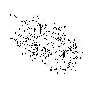
Referring to FIGS. 1 through 3, in an embodiment, a pressure relief latch 10
includes a housing 12 having a first end 14 and a second end 16 opposite the
first end
14. The housing 12 includes first and second side members 18, 20, each of
which
extends from the first end 14 to the second end 16 and includes an outer
surface 21, an
inner surface 23 opposite the outer surface 21, and an elongated slot 22
extending from
the outer surface 21 to the inner surface 23 and intermediate the first and
second ends
14, 16. Each of the side members 18,20 further includes a tab 24 having a
first hole 26
extending from the outer surface 21 to the inner surface 23 and a second hole
28
located proximate to the first end 14 and extending from the outer surface 21
to the
5
CA 3062203 2019-11-21
inner surface 23. A space 30 is formed between the inner surfaces 23 of the
first and
second side members 18, 20. In an embodiment, the housing 12 further includes
a
base portion 32 formed at the second end 16 thereof. The base portion 32
includes first
and second coves 34, 36 each of which is positioned adjacent to the outer
surface 21 of
a corresponding one of the first and second side members 18, 20. The base
portion 32
further includes a slot 38 located intermediate the coves 34, 36 and extending
from an
upper surface 39 of the base portion 32 to the space 30. In an embodiment, the
slot 38
is substantially rectangular in shape. The housing 12 further includes a
mounting
portion 40 having a slot 42 that extends from an upper surface 43 of the
mounting
1.0 portion 40 to the space 30, and a plurality of mounting holes 44. In an
embodiment, the
slot 42 is substantially rectangular in shape.
In an embodiment, the pressure relief latch 10 includes a bolt 46. In an
embodiment, the bolt 46 is J-shaped. In other embodiments, the bolt 46 can
have a U-
shape or any other suitable shape. In an embodiment, the bolt 46 includes a
first end
48 located on an arcuate/curvilinear portion 50 and a second end 52 located on
a linear
portion 54. In an embodiment, the bolt 46 includes a bolt notch 56 formed
within the
linear portion 54 and adjacent to one end of the curvilinear portion 50. A
slot 58 is
formed within the first end 48 of the bolt 46. In an embodiment, the bolt 46
is mounted
rotatably to the housing 12 such that the first end 48 of the bolt 46 is
mounted to the first
end 14 of the housing 12 by a rivet 60a, which is inserted within the hole 28.
In an
embodiment, the linear portion 54 of the bolt 48 extends through the space 30
when the
bolt 46 is in a first position, and the second end 52 of the bolt 46 extends
through and
protrudes from the slot 42 of the mounting portion 40 when the bolt 48 is in
its first
6
CA 3062203 2019-11-21
position. A torsion spring 62 is positioned on the rivet 60a and within the
slot 58 of the
bolt 46.
In an embodiment, the pressure relief latch 10 includes a trigger 64. In an
embodiment, the trigger 64 is substantially "Z" in shape. In other
embodiments, the
trigger 64 includes other suitable shapes and sizes. In an embodiment, the
trigger 64
includes a first end 66 and a second end 68. The second end 68 of the trigger
64
includes trigger slot 70 and a hole 72 (see FIG. 3). In an embodiment, the
trigger 64 is
mounted rotatably to the housing 12 such that the second end 68 of the trigger
64 is
mounted to the holes 26 of the tabs 24 of the housing 12 by another rivet 60b
extending
through the hole 72, and a pin 74 having a roller 76 mounted thereon extending
through
the trigger slot 70 and the elongated slots 22 of the side members 18, 20. The
first end
66 of the trigger 64 extends through and protrudes from the slot 38 of the
base portion
32. In an embodiment, the pin 74 and the roller 76 combination are sized and
shaped
to engage the bolt notch 56 of the bolt 46 when the latch 10 is in its closed
position.
In an embodiment, the pressure relief latch 10 includes first and second
compression springs 78, 80 each of which is positioned within a corresponding
one of
the coves 34, 36 of the base portion 32 of the housing 12. One end of each of
the
springs 78, 80 is positioned against a rear interior portion 81 of a
corresponding one of
the coves 34, 36 of the base portion 32, while the other end of each of the
springs 78,
80 includes a corresponding side cap 82 mounted thereon, which receives the
pin 74
and the roller 76 combination.
FIG. 4 shows the areas on the latch 10 where it can be opened. That is, the
latch 10 can be opened manually by a human finger (or other implement) on the
first
7
CA 3062203 2019-11-21
= end 66 of the trigger 64, or it can be opened automatically when a
defined load is
reached on the first end 48 on the bolt 46.
Referring to FIGS. 5 and 6, in an embodiment, the latch 10 may be opened from
its first, closed position to its second, open position under a defined load.
As an
example of a "defined load," when pressure builds up and reaches a defined
pressure
inside an engine compartment, the latch 10 pushes the engine compartment door
open
to release the pressure. When the defined load is reached, the bolt 46 rotates
clockwise and pushes the roller 76, which is guided by the pin 74, in the
elongated slots
22 of the side members 18, 20 of the housing 12 toward the second end 16 of
the
1.0
housing 12, and loaded by the compression springs 78, 80 away until the bolt
46
disengages the bolt notch 56 and stops. The bolt 46 is retained in its open
position
under the load of the torsion spring 62 acting thereon. In this regard, the
trigger slot 70
allows the pin 74 and the roller 76 to move only in one direction, which is a
direction
away from the bolt 46 and toward the second end 16 of the housing 12.
Referring to FIG. 7, in an embodiment, the latch 10 may be opened from its
first,
closed position to its second, open position manually. From its closed
position, the latch
10 can be opened by finger pressure on the first end 66 of the trigger 64,
which pivots
about the rivet 60b and rotates counterclockwise. In this regard, the trigger
64 pulls the
pin 74 and roller 76 away from the bolt notch 56 of the bolt 46 until they
disengage one
another, thereby enabling the bolt 46 to automatically rotate counterclockwise
under the
load of the torsion spring 62 and is retained in open position.
In an embodiment, from its open position, the latch 10 can be closed manually
by
finger pressure on the second end 52 of the bolt 46, which pivots about the
rivet 60a to
8
CA 3062203 2019-11-21
= rotate counterclockwise. In this regard, when the bolt 46 makes contact
with the roller
76, the bolt 46 pushes the pin 74 and roller 76 away until the roller 76
engages the bolt
notch 56 of the bolt 46. The bolt 46 is then retained in closed position.
It should be understood that the embodiments described herein are merely
exemplary and that a person skilled in the art may make many variations and
modifications without departing from the spirit and scope of the invention.
All such
variations and modifications are intended to be included within the scope of
the
invention as defined in the appended claims.
CA 3062203 2019-11-21