Note: Descriptions are shown in the official language in which they were submitted.
CA 03063796 2019-11-15
1
Method for producing a wear-resistant steel pipe, wear-resistant steel pipe,
and use of such a steel pipe
The invention relates to a process for producing a wear-resistant steel pipe.
The invention likewise relates to a highly wear-resistant steel pipe and the
advantageous use thereof.
The brochure "Production processes for steel pipes (Herstellverfahren fur
Stahlrohre)" (see http://www.smrw.de/Deutsch/messen-und-
medien/publikationen/publikationen.html) written by Dr.-Ing. Karl-Heinz
Brensing
et al. and published by Mannesmannrohren¨Werke AG contains an overview of
the conventional processes for producing steel pipes. According to this
publication, welded steel pipes having diameters of from 6 to 2500 mm and wall
thicknesses of 0.5-40 mm are usually produced with a longitudinal seam or with
a
helical seam. As starting material, use is generally made of rolled sheets
which,
depending on the production process, pipe dimensions and intended use, can
consist of hot-rolled or cold-rolled strip steel, hot-rolled wide strip or
heavy plate.
The physical properties and the surface quality required of the pipe are in
many
cases already present in the rolled flat product but can if required also be
set by a
heat treatment following shaping of the pipe or by cold strengthening of the
pipe.
Here, forming of the respective sheet material into the pipe can be carried
out hot
or cold in continuous pipe forming or in individual pipe forming. In
continuous pipe
forming, uncoiled strip material is taken off from a reservoir while a fresh
strip is
welded on at the end of the uncoiled strip. The "continuous" strip produced in
this
way is shaped in a continuous process into the pipe. In the case of the
individual
pipe manufacture, pipe shaping and welding process are, in contrast, not
carried
out in multiple lengths but in individual pipe lengths. In the shaping
operation, the
CA 03063796 2019-11-15
2
sheet material is shaped into a tubular preform in which the longitudinal
edges of
the sheet are opposite one another and between them bound a welding gap which
is closed by use of conventional welding processes which have been known for a
long time for this purpose.
One process which allows, in individual pipe manufacture, pipes to be formed
from sheets having a high thickness of, for example, at least 15 mm ("heavy
plates") is the "U-0 process" described in chapter 4.2.3 of the brochure"
Production processes for steel pipes (Herstellverfahren fur Stahlrohre)". In
this
process, the respective sheet is in a first step shaped into a preform having
a U-
shaped cross section, from which a preform having an 0-shaped cross section is
then formed in a second step, with the longitudinal edges of the cut-to-size
sheet
bounding a join slit extending over the length of the preform. The preform
obtained in this way is in the technical field also referred to as "round slit
pipe".
Helical pipe production is described in chapter 4.2.4 of the brochure"
Production
processes for steel pipes (Herstellverfahren kir Stahlrohre)". This production
route
starts out from a cut-to-size sheet which is strip-like and has a width
smaller than
the circumferential length of the pipe to be produced, while its length is
significantly greater than the length of the pipe to be produced. The sheet of
this
size is wound in a spiral fashion into a hollow body which has a circular
cross
section and in which the join bounded by the longitudinal edges of the cut-to-
size
sheet which are opposite one another accordingly runs in a helical fashion
around
the hollow body. Helical pipe production is particularly suitable for
continuous
"never ending" pipe production.
The demand for large pipes for the transport of mechanically wearing media
which
bring about abrasive wear is increasing steadily. These media, for example
alluvial sands, are transported through pipelines over long distances in order
to
progress land recovery. Here, the hard, fast-flowing sand grains come into
contact
CA 03063796 2019-11-15
3
with the inside of the pipeline and considerable wear arises. The abrasive
stress
on the pipes occurring in this way leads to short lives and high capital and
maintenance costs for the pipeline systems.
Other uses of large pipes of the type in question here are, for example, the
transport of oil sands or other fluids which comprise particulate, hard
constituents
and accordingly cause high-material-removing stress on the conduit pipes.
Pipes intended for the abovementioned purposes are conventionally produced in
the thickness range up to 25 mm from hot strip grades having strengths of up
to
about 350 N/mm2 by helical seam pipe welding by means of underpowder welding
methods (UP welding). In the thickness range above 25 mm, production is
carried
out from heavy plates which in the individual process are shaped by means of
U/O forming into pipes and welded with a longitudinal seam.
One approach for improving the life of steel pipes which in use are subject to
abrasive stress was to use known, highly wear-resistant steels. Such steels
acquire their wear resistance from a specific alloy composition and a heat
= treatment matched thereto. An example of such a steel is the steel alloy
known
under the name "XAR 450", which contains (in % by weight) less than 0.22% of
C,
less than 1.5% of Mn, less than 0.8% of Si, less than 1.3% of Cr and less than
0.5% of Mo in addition to iron and unavoidable impurities. At a maximum sheet
thickness of 100 mm, this steel has, in the quenched state, a hardness HB of
410-480 (see brochure "Steel XAR", October 2016 edition, catalog No. 0606,
broschueren.steel@thyssenkrupp.com).
Another steel suitable for producing highly wear-resistant pipes is known from
DE
34 14 477 C2. This steel consists (in % by weight) of 0.7-1% of Mn, 0.7-2.2%
of
Cr, 0.3-0.6% of Mo, 0.5-2.2% of Ni, not more than 0.45% of C and iron and
usual
admixtures as the remainder and is said to make it possible to produce
weldable
CA 03063796 2019-11-15
4
pipes which are subject to high abrasive stresses, for example in an oil field
or
other comparable uses. The mechanical properties of the sheets consisting of
this
steel are set in a heat treatment process in which a steel sheet made of this
steel
is heated to an austenitizing temperature of about 860 C, subsequently
quenched
from this temperature to a temperature of 90 C and then tempered at a
temperature of 350-450 C. After slit pipes have been formed from the steel
sheets
which have been tempered in this way, these slit pipes are then to be heated
locally to a temperature of about 250 C and then provided with a multilayer
welded seam. The first welding layer is to be applied at a temperature of
about
250 C and the subsequent layer at a temperature of 200 C. It is said that a
thermal after-treatment of the welded seam can be saved in this way.
US 5,397,654 A describes another concept for a highly wear-resistant, welded
steel pipe. The steel pipe is produced from a steel which consists (in % by
weight)
of 0.05 ¨ 0.2% of C, 0.5 - 2% of Si, 0.5 ¨ 2.5% of Mn, 0.02 - 2% of Al, the
remainder iron and unavoidable impurities and can contain, in each case
optionally, 0.05 - 1% of Cu, 0.05 - 2% of Ni, 0.05 ¨ 2% of Cr, 0.05 - 1% of
Mo,
0.005 ¨ 0.1% of Nb, 0.005 ¨ 0.1% of V, 0.005 ¨ 0.1% of Ti or 0.0003 ¨ 0.002%
of
B. The steel pipe has a Vickers hardness HV of 200 - 350 and is produced by
shaping a sheet consisting of the steel by hofforming into the pipe and
subsequently welding it along a longitudinal seam. Before or after this
welding, the
pipe is subjected to a heat treatment. In this heat treatment, the pipe is
heated to
a temperature which is between the AC3 temperature and the AC1 temperature,
and is then quenched by means of water.
Regardless of the way in which they are produced, a fundamental problem
associated with welded pipes made of hardened metal sheets is that the
introduction of heat into the so-called "heat influence zone", which
unavoidably
occurs when welding the pipes, leads to local tempering, as a result of which
the
hardness of the pipe steel decreases greatly in the region around the welded
CA 03063796 2019-11-15
seam compared to the hardness outside the heat influence zone. This softening
results in a local decrease in the wear resistance, which reduces the life of
the
overall component. Although the welded product also generally has a relatively
low hardness and thus wear resistance, this is in practice compensated for by
the
so-called "seam protrusion", i.e. a relatively great accumulation of welding
material on the inside of the tube in the region of the welded seam. The
decreased hardness of the steel in the heat influence zone, on the other hand,
leads to local increased removal of material which shows up as a highly
structured
surface (alternating sequence of hills and valleys formed on the inside of the
pipe
in the region of the seam). The flow of the medium conveyed along the inside
of
the pipe is adversely affected thereby, which in turn leads to increased local
wear,
known as scouring, in these zones.
A further problem in the processing of wear-resistant steels results from
these
steels being able to be deformed only with difficulty when they have been
processed to form a sheet and hardened. The setting of a high hardness to
achieve the wear resistance is generally associated with a high yield point,
so that
wear-resistant steels in the hardened or tempered state as supplied are
generally
not suitable for forming into a pipe.
In the light of the above-described prior art, it is the object of the
invention to
develop an industrially usable process for producing wear-resistant steel
pipes
having an optimized life.
In addition, a steel pipe having optimized wear resistance should be provided.
Finally, advantageous uses of such a steel pipe should be indicated.
CA 03063796 2019-11-15
6
In respect of the process, the invention has achieved this object in that at
least the
working steps indicated in claim 1 should be completed in the production of
highly
wear-resistant steel pipes.
The features of a steel pipe which achieves the abovementioned object are
specified in claim 13.
Industrially relevant uses of the pipe according to the invention are
indicated in
claim 15.
Advantageous embodiments of the invention are indicated in the dependent
claims and will be explained in detail below, as will the general inventive
concept.
A process according to the invention for producing a steel pipe accordingly
comprises the following working steps:
a) provision of a steel sheet which consists of a wear-resistant, hardenable
steel,
with the steel sheet being provided in an unhardened or tempered state;
b) shaping of the steel sheet into a tubular preform in which two
longitudinal edges
of the steel sheet are positioned opposite one another and bound a welding gap
between them;
c) welding of the longitudinal edges which are arranged opposite one
another and
bound the welding gap to form a welded seam which closes the welding gap;
d) heat treatment of the steel pipe obtained after the working step c),
wherein the
heat treatment comprises the following working steps:
d.1) heating of the steel pipe at an average heating rate of 5 - 400 Kis to a
hold
temperature which is at least equal to the Ac3 temperature of the steel and
is not more than 1100 C;
CA 03063796 2019-11-15
7
d.2) holding of the steel pipe at the hold temperature for 1 - 120 s
and
d.3) cooling of the steel pipe at an average cooling rate of 10- 600 Kis to
room
temperature.
The steel sheet provided in working step a) can consist of wear-resistant and
hardenable steels which are known per se and have been described above.
However, steel sheets composed of a steel which consists (in % by weight) of
C: 0.2 - 0.4%,
Si: 0.1 - 0.9%,
Mn: 1.0 - 2.0%,
S: up to 0.03%,
P: up to 0.04%,
and in each case optionally an element or a plurality of elements selected
from the group "Cr, Mo, Ni, Ti, B", with the proviso
Cr: 0.1 - 2.0%,
Mo: 0.3 - 0.7%,
Ti: up to 0.04%,
Ni: up to 2.0%,
B: up to 0.004%,
and iron and unavoidable impurities as the remainder
have been found to be particularly suitable for the purposes of the invention.
C contents of 0.2 ¨ 0.4% by weight ensure the hardenability in the steel used
according
to the invention.
The Si content of at least 0.1% by weight in the steel processed according to
the
invention brings about satisfactory deoxidation and hardenability of the
steel. Restricting
CA 03063796 2019-11-15
8
the Si content to not more than 0.9% by weight at the same time ensures
satisfactory
red scale resistance and toughness. The steel processed according to the
invention can
be optimized in respect to these properties by the Si content being not more
than 0.4%
by weight. On the other hand, if the Si content is increased to at least 0.6%
by weight,
an optimized hardenability is established.
Mn contents of 1.0 ¨ 2.0% by weight in the steel used according to the
invention
contribute to good hardenability and ductility. In order to be able to utilize
this effect
particularly reliably, it can be advantageous to increase the Mn content to at
least 1.1%
by weight. Restricting the Mn content to not more than 1.5% by weight can
decrease the
tendency for banded segregations.
S and P are undesirable accompanying elements in the steel according to the
invention.
In order to avoid their interfering influence reliably, the S content of the
steel is restricted
to not more than 0.03% by weight and the P content of the steel is restricted
to not more
than 0.04%.
Optional addition of Cr in contents of 0.1 ¨ 2.0% by weight makes it possible
to achieve
an increased wear resistance in the steel processed according to the
invention. Here, it
can be advantageous to increase the Cr content to at least 1.0% by weight in
order to
achieve improved corrosion resistance. On the other hand, if the Cr content is
restricted
to not more than 0.5% by weight, better elongation values tend to be able to
be
achieved.
A likewise optional addition of 0.3 ¨ 0.7% by weight of Mo makes it possible
to bring
about grain refinement and to reduce the critical cooling rate.
Ti can be added, likewise optionally, to the steel according to the invention
in order to
bind nitrogen and thus improve the hardenability-promoting action of boron.
Here, Ti
CA 03063796 2019-11-15
9
contents of at least 0.025% by weight have been found to be particularly
advantageous
in this respect.
Optionally present contents of Ni of up to 2.0% can contribute to an increase
in the yield
strength and tensile strength.
Furthermore, B can optionally be added to the steel according to the invention
in
contents of up to 0.004% in order to improve the hardenability. B contents of
at least
0.0008% by weight have been found to be particularly advantageous for this
purpose.
The steel sheets provided according to the invention can be produced in a
conventional way by casting an appropriately alloyed steel melt into an
intermediate (slab, thin slab or cast strip) and, after the usual
pretreatments have
been carried out, hot rolling this intermediate into a hot-rolled flat
product. The flat
product can be a steel strip or a steel sheet having a relatively great
thickness,
= known as "heavy plate".
For the purposes of the invention, it is important that the steel sheet
provided in
working step a) of the process of the invention is in the unhardened or
tempered
state. Steel sheets which are in this state can be preformed significantly
more
simply and to a greater degree than the hardened steel sheets which are
usually
shaped into pipes in conventional processes.
The forming of the steel sheet carried out in working step b) into the preform
can
accordingly be carried out comparatively easily. The preform is, especially in
the
case of a steel pipe produced by individual manufacture, typically a slit pipe
in
which the welding gap extends over the length of the pipe parallel to the
longitudinal axis thereof, or, especially in the case of continuous
production, is a
helical winding wound uniformly around the longitudinal axis of the pipe, in
the
case of which the welding gap runs circumferentially in the manner of a helix
with
CA 03063796 2019-11-15
an optimally uniform pitch around the hollow space enclosed by the helical
winding.
The shaping of the pipe itself can be carried out in any of the known ways
described, for example, in the brochure mentioned above. Thus, the working
step
b) can if necessary be completed in two or more substeps. This can be useful
particularly in the processing of particularly thick sheets having a thickness
of, for
example, more than 40 mm.
For individual manufacture, the steel sheet can, in working step a), be
provided as
cut-to-size sheet whose width corresponds to the circumferential length and
whose length corresponds to the length of the steel pipe to be produced. Such
a
steel sheet can then be shaped in the U-0 process into the pipe by forming a
preform having a U-shaped cross section from the steel sheet in a first
working
substep and forming a preform having a circular or ellipsoidal cross section
from
the U-shaped preform in a second working substep.
As an alternative, it is of course likewise conceivable for the steel sheet to
be,
especially for a continuous production process, provided in working step a) as
a
strip section having a width which is smaller than the circumferential length
of the
steel pipe to be produced and having a length which is greater than the length
of
the steel pipe to be produced and for this steel sheet then to be wound
following a
screw line into the tubular preform in working step b).
If necessary, shaping of the steel sheet in working step b) into the preform
can be
carried out, at least in one working substep, as hotforming. This can be
advantageous in order to limit the forming forces required for shaping the
steel
sheet.
CA 03063796 2019-11-15
11
In respect of working step b), the invention proceeds from the recognition
that the
forming in the production of helical-seam-welded or longitudinal-seam-welded
large pipes is not determined by the forming capability of the materials.
Thus,
taking into account the large pipe diameter and wall thicknesses, the
elongation
required for shaping of the pipes is significantly less than 3%. The limiting
factor in
carrying out the forming process is instead the forming force required, which
is
determined by the geometry (radius, wall thickness) and the material
properties
(alloy, microstructure and yield strength) of the steel sheet from which the
steel
= pipe is to be made.
Thus, the invention allows steel sheets having a thickness of at least 15 mm,
in
particular at least 25 mm or even at least 40 mm, to be shaped without
problems
into steel pipes.
Here, the pipes according to the invention can have diameters of more than
450 mm without problems.
The advantage of the invention here is minimization of the forming force
required
for shaping the pipe even when using highly wear-resistant alloys, since the
setting of the microstructure occurs in the final working step d).
This working step d) can also be referred to as "homogenizing heat treatment"
because a uniform microstructure in the steel of at least the steel sheet from
which the pipe is formed is obtained by means of this heat treatment, in
particular
also in the zone which is influenced by the introduction of heat during
welding. A
high microstructural homogeneity over the entire component including the
welding
seam can be achieved by the alloy composition of the welding material
introduced
to close the welding gap being matched to the composition of the steel of the
steel
sheet from which the pipe is formed, so that, from the point of view of the
alloy
too, a more homogeneous state of the component is achieved and an overall
CA 03063796 2019-11-15
12
uniform behavior of the materials coming together in the welding seam is
ensured
during the heat treatment.
The invention thus makes it possible to avoid softening of the steel material
in the
heat influence zone. Instead, there are at most only comparatively small
hardness
differences between the welding seam and the adjacent regions of the steel
pipe
and also the other regions of the steel pipe in the case of a steel pipe
produced
according to the invention.
Associated with this effect, the wear resistance even in the region of the
steel pipe
adjoining the welded seam is increased, so that an overall increased life of a
steel
pipe produced according to the invention is ensured. At the same time, the
outlay
required for shaping the pipe is minimized in the procedure according to the
invention. This allows highly wear-resistant steels which would be deformable
only
with great difficulty, if at all, in a conventional procedure to be used for
the
purposes of the invention.
A steel pipe according to the invention having a diameter of at least 200 mm,
a wall
thickness of at least 15 mm and a welded seam extending linearly in the
longitudinal
direction of the steel pipe or running in a helical fashion around the
longitudinal axis of
the steel pipe is accordingly characterized
- in that it is formed from a steel sheet which consists of
C: 0.2 - 0.4%,
Si: 0.1 - 0.9%,
Mn: 1.0 - 2.0%,
S: up to 0.03%,
P: up to 0.04%,
and, in each case optionally, an element or a plurality of elements selected
from the group "Cr, Mo, Ni, Ti, B", with the proviso
Cr: 0.1 - 2.0%,
CA 03063796 2019-11-15
13
Mo: 0.3 - 0.7%,
Ti: up to 0.04%,
Ni: up to 2.0%,
B: up to 0.004%,
and iron and unavoidable impurities as the remainder
and
- in that the difference between the hardness of the heat influence zone
adjoining the
welded seam of the steel pipe and the hardness of the steel sheet outside the
heat
influence zone is not more than 30 HV10.
When mention is made here of the "difference" between the hardness of the heat
influence zone surrounding the welded seam of the steel pipe and the hardness
of
the steel sheet outside the heat influence zone, what is meant is the absolute
value of the difference between the hardness values determined for the heat
influence zone and the region located outside the heat influence zone.
The advantage arising therefrom, namely the absolute hardness difference
between base material and the heat influence zone not being more than 30 HV10,
is the fact that the wear process into the depth of the material in the region
directly
adjoining the welded seam is increased to the level of the base material and
thus
occurs uniformly, which enables the life of the component to be fully
exploited.
The hardness of the steel sheets used according to the invention before the
heat
treatment according to the invention is typically 180 ¨ 210 HV10 and after the
heat
treatment according to the invention is typically 450 - 550 HV10.
The Vickers hardness values indicated here are determined in a manner known
per se in accordance with DIN EN ISO 6507-1:2006-03.
CA 03063796 2019-11-15
14
A steel pipe according to the invention can optimally be produced by employing
a
process according to the invention.
A steel pipe having the nature according to the invention has an optimal
resistance to abrasive wear, which is reflected in a significantly reduced
removal
of material per unit time and thus an increased life of the component.
The welding in working step c) can be carried out in any way which is known
from
the prior art and is suitable. Welding by the underpowder welding method,
which
is tried and tested in industrial use and has a high fusion performance and
good
economics has been found to be particularly useful here.
The required hardness and strength is gained by the steel of a steel pipe
having
the nature of and produced according to the invention as a result of the heat
treatment completed in working step d).
In this heat treatment, the pipe is firstly heated at a sufficient heating
rate to a hold
temperature at which it is held until the pipe has been heated all through,
i.e. as a
whole is at the hold temperature. The lower limit of the average heating rate
is
selected so that the risk of distortion of the pipe as a result of heating is
avoided
and at the same time an optimal heating result from economic-energy points of
view is also achieved. At the same time, the average heating rate is
restricted to
not more than 400 Kis because in this way satisfactory heating all through due
to
heat conduction is achieved even when the heat input, for example in an
inductive
or conductive heating operation, occurs in a locally restricted region.
The hold temperature and the hold time are selected so that firstly reliable
heating
all through of a steel pipe produced according to the invention, even taking
into
account the large wall thickness, is ensured and secondly an almost complete
austenitic microstructure, which is the prerequisite for achieving a maximum
CA 03063796 2019-11-15
hardness, is present in the steel. At the same time, the hold temperature is
restricted to not more than 1100 C in order to counter undesirable enlargement
of
the grain size. Likewise, the hold time is restricted to 120 sin order to
avoid
coarse grain and excessive scale formation.
After the hold time, the pipe is quenched to room temperature, with the
average
cooling rate being at least 10 K/s, in order to attain the required hardness.
The
average cooling rate is not more than 600 Kis because a greater cooling rate
is
. difficult to realize in industry and no increase in the maximum hardness is
to be
expected at cooling rates above 600 K/s.
The heating parameters in the working step d) are, according to the invention,
selected so that heating can be brought about by means of an inductively
operating heating device which is known per se for this purpose. In inductive
heating, the pipe to be heated is conveyed continuously through one or more
ring-
shaped inductors and thus subjected to an alternating electromagnetic field.
In
this way, eddy currents are generated without contact in the steel material of
the
pipe subjected to the alternating field and heat arises.
Even if it is in principle possible to introduce a pipe which has been shaped
and
welded in the working steps b) and c) of the process according to the
invention
into a furnace in order to bring it to the hold temperature and maintain it at
this
temperature, a particularly advantageous variant of the invention provides for
the
heating to the hold temperature and the holding at the hold temperature to be
carried out by means of inductive heating, with such inductive heating
typically
being carried out in continuous passage and the pipe in this case according to
the
invention thus not being heated in one piece to the hold temperature, held
there
and cooled but instead the heat treatment as per working step d) being carried
out
successively, for example starting from one end of the steel pipe, in a
continuous
process over its length.
CA 03063796 2019-11-15
16
As an alternative to inductive heating, conductive heating carried out with
continuous passage in a manner corresponding to inductive heating is also
conceivable, in which case the section of the pipe to be heated itself forms
part of
the electrical circuit provided for the introduction of heat.
Steel pipes produced according to the invention or having the nature according
to
the invention are particularly suitable for the transport of bulk materials,
fluids or
mixtures thereof flowing through them because of their maximal wear
resistance.
Here, pipes produced according to the invention or having the nature according
to
the invention can be used for land recovery, in, for example, offshore dredges
used for washing up sand, for waste disposal, in or on extruders, in the
transport
of snow or ice transportation, in bulk material transport in the chemical
industry or
the food industry (e.g. for the transport of cereal), in the field of power
stations or
cement works, in the utilization of water power, in ore recovery or the
transport of
ores and comparable rock applications, in the transport of oil sand, in the
mining
industry, in fracking, in all industrial applications in which fluids loaded
with
particles are conveyed, in concrete pumps and in general coal mining.
The invention will be illustrated below with the aid of a working example. In
the
figures:
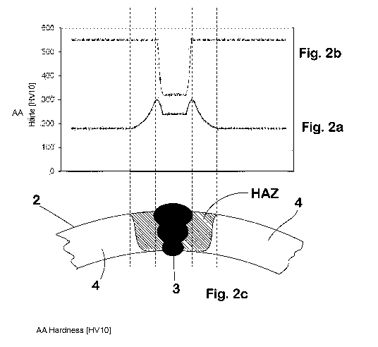
Fig. 1 shows a frontal view of a longitudinal-seam-welded steel pipe produced
according to the invention;
Fig. 2a shows the course of the hardness in the region of the longitudinal
welded
seam of the steel pipe of Fig. 1 after welding and before the heat
treatment;
Fig. 2b shows the course of the hardness in the region of the longitudinal
welded
seam of the steel pipe of Fig. 1 after the heat treatment;
=
CA 03063796 2019-11-15
17
Fig. 2c shows a section of Fig. 1.
The steel pipe 1 having a circular cross section and an external diameter D of
800 mm which is shown in Fig. 1 has been produced from a cut-to-size sheet
having a thickness d of 20 mm, the width of which corresponds to the
circumferential length of the steel pipe 1 and the length of which corresponds
to
the length of the steel pipe Ito be produced.
The steel sheet 2 consisted of a steel having the composition shown in Table
1.
C Si Mn P S Cr B Ti Mo Ni
0.3 0.25 1.3 0.02 0.01 0.3 0.0025 0.032 0.05 0.05
Figures in % by weight: remainder iron and unavoidable impurities
Table 1
The steel sheet 2 which has this composition and is provided in the unhardened
delivery state has been formed in a manner known per se in individual
manufacture firstly into a preform configured as a slit pipe, in which preform
the
longitudinal edges of the steel sheet 2 were arranged opposite one another and
between them bound a welding gap extending over the length of the steel pipe
1.
The preform was subsequently welded by the welding gap being closed in a
manner known per se by means of underpowder welding method to form a
longitudinal welded seam 3 extending over the length of the steel pipe 1. As a
result of the welding and the introduction of heat associated therewith,
hardening
effects have occurred in the heat influence zones HAZ extending over the
longitudinal edge regions of the steel sheet 2 which laterally adjoin the
welded
seam 3, due to which hardening effects the hardness of the steel sheet 2 in
the
heat influence zones HAZ was higher than in the regions 4 of the steel sheet 2
which were located outside these zones HAZ and were uninfluenced by the
welding heat introduced (Fig. 2a).
CA 03063796 2019-11-15
18
After welding, the steel pipe 1 was heated by means of inductive heating at a
heating rate of 9 Kis to a hold temperature of 930 C at which it was held for
20 seconds in order to achieve reliable heating all through.
After the hold time, the steel pipe 1 was cooled at a cooling rate of 30 Kis
to room
temperature (25 C).
The hardness HV10 of the thus heat-treated steel pipe 1 was measured in
= accordance with DIN EN ISO 6507-1:2006-03 in agreement with the procedure
set down in DIN EN ISO 3183:2012 in the heat influence zones HAZ and the
regions 4 of the steel pipe located outside. The hardness indentations were
arranged 1.5 mm below the surface. The hardness profile determined in this way
is depicted in Fig. 2b. It is found that the absolute value of the difference
between
the hardness in the outer regions 4 and the hardness in the heat influence
zones
HAZ was not more than 20 HV10.