Note: Descriptions are shown in the official language in which they were submitted.
CA 03063912 2019-11-15
WO 2018/226628 PCT/US2018/035961
MECHANICALLY EXPANDABLE HEART VALVE
FIELD
[001] The present disclosure relates to implantable, mechanically expandable
prosthetic
devices, such as prosthetic heart valves, and to methods and assemblies for
providing
collapsible frames for, and including, such prosthetic devices.
BACKGROUND
[002] Malfunctions within the human heart, such as those resulting from
valvular diseases,
frequently require repair of the native valve or replacement of the native
valve with an
artificial valve. There are a number of known repair devices (e.g., stents)
and artificial
valves, as well as a number of known methods of implanting these devices and
valves in
humans. In one known technique, a prosthetic device is configured to be
implanted in a less
invasive procedure by way of catheterization. For example, a collapsible
transcatheter
prosthetic heart valve can be crimped to a compressed state and percutaneously
introduced in
the compressed state on a catheter and expanded to a functional size at the
desired position by
mechanical expansion or using a self-expanding frame or stent. Current frame
assembly
designs, however, frequently require manufacturing processes requiring
handling and
assembling many small parts. Improved implant frame designs and methods for
assembly are
needed. Such frame assemblies would preferably offer one or more of the
following
advantages over current approaches: minimizing the number of individual parts
needed,
maintaining flexibility for movement within the patient, collapsing to a low
profile to
minimize the size of catheter needed during introduction into the patient, and
reducing the
risk of rivet embolization.
SUMMARY
[003] Embodiments of improved implantable medical devices, such as prosthetic
heart
valves, are disclosed herein, as well as methods for providing such devices
and assemblies.
[004] In one representative embodiment, a method of assembling an implantable
medical
device comprises providing a plurality of struts, each strut comprising a
length and a plurality
of apertures spaced apart from each other along the length. The method can
further comprise
providing a plurality of strut connectors comprising an elongated support
member and a
plurality of projections spaced apart from each other along the support
member. The method
can further comprise connecting the struts to each other with the strut
connectors to form an
- 1 -
CA 03063912 2019-11-15
WO 2018/226628 PCT/US2018/035961
annular frame, wherein the projections of each strut connector extend through
respective
apertures of one of the struts and into respective apertures of one or more
other struts to form
a plurality of pivot joints between the struts.
[005] In some embodiments, the plurality of struts comprises a first set of
inner struts and a
second set of outer struts, wherein the inner struts are connected to the
outer struts by the strut
connectors.
[006] In some embodiments, the strut connectors are placed against respective
outer struts
and each strut connector comprises at least first and second projections that
extend through
apertures of the same outer strut and into apertures of different inner
struts.
[007] In some embodiments, the strut connectors are placed against respective
inner struts
and each strut connector comprises at least first and second projections that
extend through
apertures of the same inner strut and into apertures of different outer
struts.
[008] In some embodiments, the method further comprises mounting a valve
member
comprising a plurality of leaflets inside of the annular frame.
[009] In some embodiments, the strut connectors are formed using
electrochemical
machining.
[010] In some embodiments, the strut connectors are formed using laser
machining.
[011] In another representative embodiment, an implantable medical device
comprises a
first set of a plurality of first struts extending in a first direction and a
second set of a plurality
of second struts extending in a second direction, wherein the first struts are
interwoven with
the second struts to form an annular frame that is radially compressible and
expandable.
Each first strut can be pivotally connected to at least one second strut.
[012] In some embodiments, each first strut can comprise a plurality of
projections spaced
apart from each along a length of the first strut and each second strut can
comprise a plurality
of apertures extending along a length of the second strut, and wherein the
projections of the
first struts extend into respective apertures of the second struts.
[013] In some embodiments, each first strut has at least one projection that
extends radially
inwardly and into an aperture of an adjacent second strut and at least one
projection extends
radially outwardly and into an aperture of an adjacent second strut.
[014] In some embodiments, the projections are integrally formed on the first
struts.
- 2 -
CA 03063912 2019-11-15
WO 2018/226628 PCT/US2018/035961
[015] In some embodiments, each first strut passes radially outside of at
least one second
strut and radially inside of at least one second strut.
[016] In some embodiments, the medical device further comprises a valve member
which
can comprise a plurality of leaflets mounted inside the annular frame.
[017] In another representative embodiment, a method of assembling a frame for
an
implantable medical device comprises providing a plurality of individual
struts comprising a
first set of a plurality of first struts and a second set of a plurality of
second struts. The
method can further comprise interweaving the first struts with the second
struts to form an
annular frame.
[018] In some embodiments, the individual struts, prior to the act of
interweaving, are
curved.
[019] In some embodiments, the individual struts, prior to the act of
interweaving, have a
radius of curvature substantially the same as the radius of curvature of the
annular frame
formed by the struts.
[020] In some embodiments, the individual struts are laser cut from a metal
tube.
[021] In some embodiments, each of the plurality of first struts is formed
with a plurality of
radially extending projections and each of the plurality of second struts is
formed with a
plurality of apertures.
[022] In some embodiments the interweaving comprises connecting the first
struts to the
second struts by extending each of the plurality of projections through a
respective one of the
plurality of apertures at junctions between a first strut and a second strut.
[023] In some embodiments, the connecting comprises pivotally connecting each
of the first
struts to a plurality of the second struts.
[024] In some embodiments, the plurality of radially extending projections are
formed with
a plurality of projections extending radially inwardly, and a plurality of
projections extending
radially outwardly.
[025] In some embodiments, the method further comprises mounting the first set
of the
plurality of struts at a first assembly angle, wherein each of the struts in
the first set of struts
comprises a plurality of the radially extending projections comprising a
central protrusion
with at least two ears extending outward therefrom in a plane parallel to the
strut formed
therein. The method can further comprise mounting the second set of the
plurality of struts
- 3 -
CA 03063912 2019-11-15
WO 2018/226628 PCT/US2018/035961
on the first set of struts at a second assembly angle forming a relative
assembly angle
between the first assembly angle and the second assembly angle. Each of the
struts in the
second set of struts comprises a plurality of the apertures, wherein each of
the apertures
comprises a central opening corresponding to the central protrusion and oblong
side openings
corresponding to the at least two ears. In this embodiment, the mounting forms
the frame.
[026] In certain embodiments, the method can further comprise crimping the
frame to cause
the at least two ears on the first set of struts to rotate away from the
corresponding oblong
side openings in the second set of struts. The method can further comprise
securing a
plurality of mechanical lockers to the frame to limit the relative movement of
the first set of
struts and the second set of struts to a range of relative angles that does
not include the
relative assembly angle.
[027] In another representative embodiment, an implantable medical device
comprises a
radially expandable and compressible annular frame comprising a plurality of
interconnected
struts, the plurality of struts comprising a first set of a plurality of first
struts and a second set
of a plurality of second struts, wherein the first struts overlap adjacent
second struts at
junctions, and expansion or compression of the annular frame causes the first
struts to pivot
relative to the second struts at the junctions. Each of the first struts can
comprise a plurality of
pairs of radially extending, first stopper tabs spaced apart from each other
along a length of
the first strut, and each of the second struts can comprise a plurality of
pairs of radially
extending, second stopper tabs spaced apart from each other along a length of
the second
strut.
[028] In particular embodiments, the first stopper tabs of each pair of tabs
along the first
struts extend to opposite sides of an adjacent second strut at a junction and
can engage second
stopper tabs of the adjacent second strut upon pivoting movement of the first
struts relative to
the second struts.
[029] In some embodiments, the first stopper tabs extend radially inward and
the second
stopper tabs extend radially outward.
[030] In another representative embodiment, an implantable medical device
comprises a
radially expandable and compressible annular frame comprising a plurality of
interconnected
struts, the plurality of struts comprising a first set of a plurality of first
struts and a second set
of a plurality of second struts, wherein the first struts overlap adjacent
second struts at
junctions and expansion or compression of the annular frame causes the first
struts to pivot
relative to the second struts at the junctions. Each of the first struts can
comprise a plurality
- 4 -
CA 03063912 2019-11-15
WO 2018/226628 PCT/US2018/035961
of apertures spaced apart from each other along a length of the first strut,
and each of the
second struts can comprise a plurality of apertures spaced apart from each
other along a
length of the second strut. The device can further comprise a plurality of
rivets, each rivet
extending through an aperture of a first strut and an aperture of an adjacent
second strut at a
junction, and each rivet can further comprise a first flange positioned
radially outside of a
corresponding first strut and a second flange positioned radially inside of a
corresponding
second strut.
[031] In some embodiments, each rivet comprises a third flange intermediate
the first and
second flanges and positioned radially between a first strut and a second
strut at a junction.
[032] In another representative embodiment, an implantable medical device
comprises a
radially expandable and compressible annular frame comprising a plurality of
interconnected
struts, the plurality of struts comprising a first set of a plurality of first
struts and a second set
of a plurality of second struts, wherein the first struts overlap adjacent
second struts at
junctions and expansion or compression of the annular frame causes the first
struts to pivot
relative to the second struts at the junctions, wherein the frame comprises a
plurality of
hinges at the junctions extending from the first struts through corresponding
non-circular
apertures of the second struts at the junctions.
[033] In some embodiments, each hinge comprise a cylindrical pivot portion
that can rotate
in a corresponding aperture of a second strut and a locking member extending
from the pivot
portion, wherein the locking member is sized and shaped relative to the
corresponding
aperture of the second strut so as to prevent radial separation of the first
and second struts
whenever the locking member is rotationally offset from the corresponding
aperture upon
radial expansion and compression of the frame.
[034] In some embodiments, the second struts are formed with recessed portions
surrounding the non-circular apertures and the locking members of the hinges
are disposed
within the recessed portions.
[035] In some embodiments, the implantable medical device further comprises
one or more
actuators mounted on the frame and configured to radially expand and compress
the frame
between a radially compressed state defining a compressed diameter and a
radially expanded
state defining an expanded diameter. In particular embodiments, each locking
member is
rotationally offset from corresponding non-circular apertures in the second
struts at the
compressed diameter, the expanded diameter, and all diameters in between the
compressed
and expanded diameters.
- 5 -
CA 03063912 2019-11-15
WO 2018/226628 PCT/US2018/035961
[036] In some embodiments, the hinges are integrally formed on the first
struts.
[037] In some embodiments, the hinges are separate components from the first
and second
struts. Each of the first struts can comprise a plurality of non-circular
apertures, and each
hinge extends through an aperture in a first strut and an adjacent aperture in
a second strut at
a junction.
[038] In some embodiments, each of the hinges further comprises a retaining
member
configured to be retained within the non-circular apertures on the first
struts.
[039] In some embodiments, each of the hinges further comprises a circular
base member
configured to be retained within a circular recess surrounding one of the non-
circular
apertures on the first struts.
[040] In some embodiments, the locking members comprise a non-circular shape.
[041] In some embodiments, the locking members comprise a non-circular central
protrusion with at least two ears extending outward therefrom in a plane
parallel to the strut.
[042] In another representative embodiment, a method of assembling an
implantable
medical device comprises providing a plurality of first struts and providing a
plurality of
second struts, each second strut comprising a plurality of non-circular
apertures spaced along
a length thereof. The method can further comprise connecting the first and
second struts to
each other to form an annular frame by inserting hinges through the non-
circular apertures of
the second struts, each hinge having a cylindrical pivot portion disposed in a
corresponding
non-circular aperture and a locking member extending from one end of the pivot
portion,
wherein the locking members are rotationally aligned with corresponding non-
circular
apertures when the hinges are inserted into the non-circular apertures.
[043] In some embodiments, the method can further comprise pivoting the first
struts
relative to the second struts to cause the locking members to become
rotationally offset from
their corresponding non-circular apertures, and mounting one or more actuators
on the frame,
the one or more actuators configured to radially expand and compress the frame
within a
predetermined range of diameters corresponding to a predetermined range of
angles between
the first and second struts at which the locking members are at all times
rotationally offset
from the non-circular apertures.
[044] In some embodiments, each first strut comprises a plurality of non-
circular apertures
spaced along a length thereof, and connecting the first and second struts
further comprises
inserting the hinges through the non-circular apertures of the first struts
and the second struts.
- 6 -
CA 03063912 2019-11-15
WO 2018/226628 PCT/US2018/035961
[045] In some embodiments, the hinges are integral to the first struts.
[046] In some embodiments, the first struts are interwoven with the second
struts.
[047] In another representative embodiment, an implantable medical device
comprises a
radially expandable and compressible annular frame comprising an inner frame
sub-assembly
and an outer frame sub-assembly. Each of the frame sub-assemblies can comprise
a closed
annular frame comprising plurality of interconnected struts. The plurality of
struts of each
frame sub-assembly can comprises a first set of a plurality of first struts
and a second set of a
plurality of second struts, wherein the first struts overlap adjacent and are
rotatably connected
to second struts at junctions, and expansion or compression of the annular
frame causes the
first struts to pivot relative to the second struts at the junctions.
[048] In some embodiments, each of the first struts can comprise either a
plurality of
projections spaced apart from each other along a length of the first strut or
a plurality of
apertures spaced apart from each other along a length of the first strut, and
each of the second
struts can comprise a plurality of apertures and a plurality of projections
spaced apart from
each other along a length of the second strut. At each of the junctions,
either a projection on
a first strut may be inserted through an aperture of an adjacent second strut,
or a projection on
a second strut may be inserted through an aperture of an adjacent first strut
to rotatably
connect the first strut to the second strut.
[049] In particular embodiments, each of the inner frame sub-assembly and the
outer frame
comprises at least three inner struts and three outer struts. In particular
embodiments, the
outer frame assembly comprises six inner struts and six outer struts.
[050] In some embodiments, a prosthetic valve leaflet assembly is positioned
within the
inner-frame sub-assembly. In particular embodiments, the prosthetic valve
leaflet assembly
is positioned within and secured to the inner frame sub-assembly without being
secured to the
outer frame sub-assembly. In more particular embodiments, the prosthetic valve
leaflet
assembly is positioned so that the prosthetic valve leaflets are prevented
from contacting the
outer frame sub-assembly when they open during the cardiac cycle, while in
other
embodiments such contact is minimized.
[051] In some embodiments, a skirt is positioned on the inner frame sub-
assembly. In
particular embodiments, the skirt is positioned between a first set of inner
struts and a second
set of outer struts of the inner frame sub-assembly. In another embodiment,
the skirt is
positioned on the outside of the inner-frame sub-assembly and disposed between
the inner
frame sub-assembly and the outer frame sub-assembly.
- 7 -
CA 03063912 2019-11-15
WO 2018/226628 PCT/US2018/035961
[052] In some embodiments, one or more actuators are positioned on the frame,
the one or
more actuators being configured to radially expand and compress the frame. In
particular
embodiments, the actuators may be configured to expand and compress the frame
within a
predetermined range of diameters corresponding to a predetermined range of
angles between
the first and second struts.
[053] In another representative embodiment, a method of assembling an
implantable
medical device comprises assembling an inner frame sub-assembly comprising a
plurality of
first struts and a plurality of second struts. The method can further comprise
connecting the
first and second struts to each other to form a first closed annular inner
frame sub-assembly
by connecting each of the plurality of first struts to at least two of the
plurality of second
struts. The method can further comprise assembling an outer frame sub-assembly
comprising
a plurality of third struts and a plurality of fourth struts. The method can
further comprise
connecting the third and fourth struts to each other to form a second closed
annular outer
frame sub-assembly by connecting each of the plurality of third struts to at
least two of the
plurality of fourth struts. The method can further comprise after assembling
the inner frame
sub-assembly and the outer frame sub-assembly, inserting the inner frame sub-
assembly
inside the outer frame sub-assembly and interconnecting the two sub-assemblies
at a plurality
of junctions along the struts forming a single, closed annular frame assembly.
[054] In some embodiments, the method can further comprise assembling a
leaflet assembly
on the inner frame sub-assembly. In particular embodiments, the leaflet
assembly is
assembled on the inner frame sub-assembly without contacting the outer frame
sub-assembly.
In some embodiments, a skirt is positioned on the inner frame sub-assembly. In
particular
embodiments, the skirt is positioned between a first set of inner struts and a
second set of
outer struts of the inner frame sub-assembly. In another particular
embodiment, the skirt is
positioned on the outside of the inner-frame sub-assembly and disposed between
the inner
frame sub-assembly and the outer frame sub-assembly. In another particular
embodiment,
the skirt is positioned along with a leaflet assembly on the inside of the
inner frame sub-
assembly.
[055] In some embodiments, the inner frame sub-assembly and the outer frame-
sub-
assembly are rotatably interconnected at junctions along the struts via a
plurality of hinge
members. The hinge members can comprises, for example, rivets, pins, integral
projections,
or similar mechanisms. In particular embodiments, the hinge members may pass
through two
or more of the inner frame sub-assembly, the skirt, and the outer frame sub-
assembly. In
- 8 -
CA 03063912 2019-11-15
WO 2018/226628 PCT/US2018/035961
particular embodiments, the rivets or other projections may pass through three
or more of the
prosthetic valve sub-assembly, inner frame sub-assembly, inner skirt, and
outer frame sub-
assembly. In particular embodiments an outer skirt may be attached to the
outer frame sub-
assembly.
[056] The foregoing and other objects, features, and advantages of the
invention will
become more apparent from the following detailed description, which proceeds
with
reference to the accompanying figures.
BRIEF DESCRIPTION OF THE DRAWINGS
[057] FIG. 1 is a side elevation view of an embodiment of a prosthetic valve
delivery
assembly.
[058] FIG. 2 is a side elevational view of a prosthetic valve, according to
one embodiment.
[059] FIGS. 3A and 3B are enlarged perspective views and side views,
respectively, of an
embodiment of coupled frame struts useable in the prosthetic valve of FIG. 2.
[060] FIG. 4 is a side elevational view of the frame that can be used in the
prosthetic valve
of FIG. 2.
[061] FIG. 5 is a side view of an embodiment of a flattened strut for a frame
of a prosthetic
valve, such as the frame of FIG. 4.
[062] FIG. 6 is a side view of the frame of FIG. 4 shown in a radially
compressed state.
[063] FIG. 7 is a side view of a prosthetic valve incorporating the frame of
FIG. 4 shown in
a radially compressed state.
[064] FIG. 8 is an enlarged perspective view of the distal end portion of the
prosthetic valve
delivery assembly of FIG. 1.
[065] FIG. 9 is an enlarged side view of a locking unit and the distal end
portion of a
positioning member of the prosthetic valve delivery assembly of FIG. 1.
[066] FIG. 10A is an enlarged side view of the locking and the positioning
member of FIG.
9, illustrating the positioning member decoupled from the locking unit.
[067] FIG. 10B is enlarged side view of the distal end portion of the
positioning member of
FIG. 10A rotated 90 degrees from the orientation shown in FIG. 10A.
[068] FIG. ibis an enlarged side view of the locking unit and the positioning
member of
FIG. 9 rotated 90 degrees from the orientation shown in FIG. 9.
- 9 -
CA 03063912 2019-11-15
WO 2018/226628 PCT/US2018/035961
[069] FIG. 12 is an enlarged cross-sectional view of the handle of the
prosthetic valve
delivery assembly of FIG. 1.
[070] FIG. 13 is a side elevational view of another embodiment of a frame
formed from
interwoven struts.
[071] FIG. 14A is an enlarged, partial view of another embodiment of a frame
formed from
interwoven struts.
[072] FIG. 14B is a cross-sectional view of the frame of FIG. 14A taken along
line 14B-
14B of FIG. 14A.
[073] FIG. 15A is a plan view of one embodiment of a first strut having
integral fasteners.
[074] FIG. 15B is a plan view of one embodiment of a second strut that, along
with
additional such struts, can be used with multiple of the struts shown in FIG.
15A to form a
frame.
[075] FIG. 15C is a side view of the inwardly facing surface of the strut of
FIG. 15B.
[076] FIG. 16A is a side view of a hinge of a frame formed from the struts
shown in FIGS.
15A and 15B.
[077] FIG. 16B is a cross-sectional view of the hinge of FIG 16A taken along
line 16B-16B
of FIG. 16A.
[078] FIG. 17 is a cross-sectional view of another embodiment of a hinge
formed from two
struts of a frame.
[079] FIG. 18A is a side view of another embodiment of a hinge formed from two
struts of a
frame.
[080] FIG. 18B is a side view of the opposite side of the hinge of FIG 18A.
[081] FIG. 18C is an exploded view of the hinge of FIG 18A.
[082] FIG. 19A is a side view of an embodiment of a strut connector that can
be used to
form multiple hinge connections between struts of a frame.
[083] FIG. 19B is a plan view of the strut connector of FIG 19A.
[084] FIG. 19C is a perspective view of the strut connector of FIG 19A.
[085] FIG. 20 is a perspective view of an embodiment of a frame comprising a
plurality of
struts pivotally secured using a plurality of the strut connectors shown in
FIGS. 19A-C.
- 10 -
CA 03063912 2019-11-15
WO 2018/226628 PCT/US2018/035961
[086] FIG. 21 is a perspective view of an alternative embodiment of a frame
connected
using integral hinges and corresponding slots.
[087] FIG. 22 is an enlarged, perspective view of one of the hinges formed by
two
overlapping struts of the frame of FIG. 21.
[088] FIG. 23 is an enlarged, perspective view of a portion of one of the
struts shown in
FIG. 22.
[089] FIG. 24 is an enlarged, perspective view of a portion of the other strut
shown in FIG.
22.
[090] FIG. 25 is another perspective view of the strut shown in FIG. 23 as
viewed from the
side of the strut.
[091] FIG. 26 is an enlarged, perspective view of another hinge of the frame
of FIG. 21,
showing an end portion of an actuator pivotally connected to the hinge.
[092] FIG. 27 is a perspective view showing the frame of FIG. 21 assembled on
a mandrel.
[093] FIG. 28 is a side view of the frame of FIG. 21 in a compressed state.
[094] FIG. 29 is an enlarged, perspective view of an alternative embodiment of
a hinge
connection of a frame connected using separate hinges, such as shown in FIGS.
30A-33.
[095] FIG. 30A is a perspective view of a hinge member that can be used to
form a hinge
connection between struts of a frame.
[096] FIG. 30B is a plan view of the hinge member of FIG. 30A.
[097] FIG. 30C is a side view of the hinge member of FIG. 30A.
[098] FIG. 31A is a first perspective view of the components of the hinge
assembly of FIG.
29 prior to assembly.
[099] FIG. 31B is a second perspective view of the components of the hinge
assembly of
FIG. 29 prior to assembly.
[0100] FIG. 32A is a first perspective view of the components of the hinge
assembly of FIG.
29, with the hinge member inserted through the first strut.
[0101] FIG. 32B is a second perspective view of the components of the hinge
assembly of
FIG. 29, with the hinge member inserted through the first strut.
[0102] FIG. 33 is a perspective view of the components of the hinge assembly
of FIG. 29,
with the hinge member inserted through both struts in an assembly
configuration.
- 11-
CA 03063912 2019-11-15
WO 2018/226628 PCT/US2018/035961
[0103] FIG. 34 is a perspective view of a flanged rivet that can be used to
form a hinge
connection between struts of a frame.
[0104] FIG. 35A is a perspective view of an embodiment of a frame comprising a
plurality of
struts pivotally secured using a plurality of the flanged rivets shown in FIG.
34.
[0105] FIG. 35B is an enlarged, perspective view of one of the hinges formed
by two
overlapping struts of the frame of FIG. 35A using the flanged rivet of FIG.
34.
[0106] FIG. 36 is a cross-sectional view of the hinge of FIG. 35B.
[0107] FIG. 37 is a cross-sectional view of the hinge of FIG. 35B, with the
ends of the
flanged rivet flared out.
[0108] FIG. 38A is a side view of another embodiment of a flanged rivet that
can be used to
form a hinge connection between the struts of a frame.
[0109] FIG. 38B is a cross-sectional view of the flanged rivet of FIG 38A
taken along line
38B-38B of FIG. 38A, showing drilled holes in its ends.
[0110] FIG. 39 is a cross-sectional view of a hinge formed by two overlapping
struts using
the flanged rivet of FIGS. 38A and 38B.
[0111] FIG. 40A is a perspective view of a tubular member used to form a
rivet.
[0112] FIG. 40B is a cross-sectional view of a flanged rivet formed from the
tubular member
of FIG. 40A.
[0113] FIG. 40C is a perspective view of the flanged rivet embodiment of FIG.
40B.
[0114] FIG. 41 is a perspective view of an embodiment of an inner frame sub-
assembly for a
prosthetic valve.
[0115] FIG. 42 is a perspective view of an embodiment of an outer frame sub-
assembly for a
prosthetic valve.
[0116] FIG. 43 is a perspective view of a frame for a prosthetic valve formed
by assembling
the inner frame sub-assembly of FIG. 41 and the outer frame sub-assembly of
FIG. 42, and
mounting threaded actuators thereon for frame expansion.
[0117] FIG. 44 is a perspective view of the frame of FIG. 43, shown without
the actuators.
[0118] FIG. 45 is a perspective view of a valve sub-assembly comprising the
inner frame
sub-assembly of FIG. 41 and a prosthetic valve leaflet assembly.
- 12-
CA 03063912 2019-11-15
WO 2018/226628 PCT/US2018/035961
[0119] FIG. 46 is a perspective view of another valve sub-assembly comprising
the inner
frame sub-assembly of FIG. 41, a prosthetic valve leaflet assembly and a skirt
positioned
between the struts of the inner frame sub-assembly.
[0120] FIG. 47 is a perspective view of another valve sub-assembly comprising
the inner
frame sub-assembly of FIG. 41, a prosthetic valve leaflet assembly and a skirt
positioned
entirely external to the inner frame sub-assembly.
[0121] FIG. 48 is a perspective view of a valve assembly formed by combining
the valve
sub-assembly of FIG. 47 with the outer frame sub-assembly of FIG. 42,
providing threaded
actuators for frame expansion.
[0122] FIG. 49 is a perspective view of another embodiment of an inner frame
sub-assembly
for a prosthetic valve.
[0123] FIG. 50 is a perspective view of another embodiment of an outer frame
sub-assembly
formed for a prosthetic valve.
[0124] FIG. 51 is a perspective view of another frame formed by combining the
inner frame
sub-assembly of FIG. 49 and the outer frame sub-assembly of FIG. 50.
[0125] FIG. 52 is a perspective view of the frame of FIG. 51, further
including threaded
actuators for frame expansion and commissure attachment members for a valve
leaflet
assembly.
DETAILED DESCRIPTION
[0126] Described herein are examples of prosthetic implant delivery assemblies
and
components thereof which can improve a physician's ability to control the size
of a
mechanically-expandable prosthetic implant, such as prosthetic valves (e.g.,
prosthetic heart
valves or venous valves), stents, or grafts, as well as facilitate separation
of the prosthetic
implant from the delivery assembly, during the implantation procedure. The
present
disclosure also provides frames for use with such prosthetic implants. The
frames can
comprise struts shaped to reduce or eliminate pinching of the soft components
of the
prosthetic implant (e.g., leaflets of the implant) when the implant is
radially compressed to a
delivery configuration for delivery into a patient.
[0127] FIG. 1 shows one example of a prosthetic implant delivery assembly 10
which may be
used with one or more of the embodiments of the present disclosure. The
delivery assembly
can include two main components: a prosthetic heart valve 14 and a delivery
apparatus 18.
- 13 -
CA 03063912 2019-11-15
WO 2018/226628 PCT/US2018/035961
The prosthetic valve 14 can be releasably coupled to the delivery apparatus
18, as further
described below. It should be understood that the delivery apparatus 18 and
other delivery
apparatuses disclosed herein can be used to implant prosthetic devices other
than prosthetic
valves, such as stents or grafts.
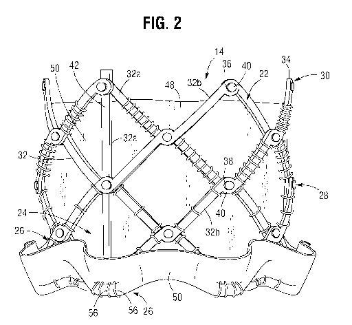
[0128] FIG. 2 is a side elevational view of the prosthetic valve 14 shown in
its deployed,
radially expanded configuration. While only one side of the prosthetic valve
14 is shown in
the drawings, it should be appreciated that the opposite side is similar to
the portion shown.
The prosthetic valve 14 can include an annular stent or frame 22, and a valve
structure 24
which can be coupled to the frame 22. The frame 22 can have an inflow end
portion 26, an
intermediate portion 28, and an outflow end portion 30. The prosthetic valve
14 can define a
longitudinal axis extending through the inflow end portion 26 and the outflow
end portion 30.
[0129] The frame 22 can be made of any of various suitable materials, such as
stainless steel
or a nickel titanium alloy ("NiTi"), for example Nitinol, or CoCr alloys, as
well. The frame
22 can include a plurality of interconnected lattice struts 32 arranged in a
lattice-type pattern
and forming a plurality of apices 34 at the outflow end 30 of the prosthetic
valve 14. The
struts 32 can also form similar apices at the inflow end of the prosthetic
valve (which are
covered by a skirt 50 in FIG. 2). The lattice struts 32 are shown as
positioned diagonally, or
offset at an angle relative to, and radially offset from, the longitudinal
axis of the prosthetic
valve. In other implementations, the lattice struts 32 can be offset by a
different amount than
depicted in FIG. 2, or some or all of the lattice struts 32 can be positioned
parallel to the
longitudinal axis of the prosthetic valve 14. The lattice struts 32 can
comprise a set of inner
struts 32a (extending from the upper left to the lower right of the frame in
FIG. 2) and a set of
outer struts 32b (extending from the lower left to the upper right of the
frame in FIG. 2)
connected to the inner struts 32a.
[0130] The lattice struts 32 can be pivotably coupled to one another. In the
illustrated
embodiment, for example, the end portions of the struts 32 forming the apices
34 at the
outflow end 30 and at the inflow end 26 of the frame 22 can have a respective
opening 36.
The struts 32 also can be formed with apertures 38 spaced apart along their
lengths between
the opposite ends of the struts. Respective hinges can be formed at the apices
34 and at the
locations where struts 32 overlap each other between the ends of the frame via
fasteners 40,
which can comprise individual rivets or pins that extend through the apertures
36, 38. The
hinges can allow the struts 32 to pivot relative to one another as the frame
22 is expanded or
contracted, such as during assembly, preparation, or implantation of the
prosthetic valve 14.
- 14 -
CA 03063912 2019-11-15
WO 2018/226628 PCT/US2018/035961
For example, the frame 22 (and thus the prosthetic valve 14) can manipulated
into a radially
compressed or contracted configuration (see, e.g., FIGS. 6 and 7) and inserted
into a patient
for implantation. Once inside the body, the prosthetic valve 14 can be
manipulated into an
expanded state (e.g., FIGS. 2 and 4) and then released from the delivery
apparatus 18 (e.g.,
FIG. 1), as further described below.
[0131] The frame 22 can be formed using any suitable technique. Suitable
techniques
include separately forming individual components (e.g., the struts 32 and
fasteners 40) of the
frame and then mechanically assembling and connecting the individual
components to form
the frame 22. The struts and fasteners can be formed, for example, by laser
cutting those
components from sheets or tubes of metal, or by electroforming (electroplating
or
electrodeposition) or physical vapor deposition, or by electro chemical
machining and/or
chemical etching.
[0132] In some embodiments, electroforming or physical vapor deposition can be
used to
form subcomponents of the frame 22 or the entire frame 22 with pivotable
connections
between the struts. In one implementation, for example, electroforming or
physical vapor
deposition can be used to form struts 32 having integral fasteners 40. The
individual struts
can be assembled together into a frame by inserting the integral fasteners 40
of each strut
through a corresponding aperture of an adjacent strut. In some embodiments,
electroforming
or physical vapor deposition can be used to form the entire frame in its
final, cylindrical, or
tubular shape. While in the illustrated embodiments, the frame 22 is shown as
generally
cylindrical in shape, other frame shapes may be used, such as, e.g., conical,
hour-glass or
barrel shaped. In other embodiments, electroforming or physical vapor
deposition can be
used to form the entire frame in a flattened configuration, after which the
ends of the
flattened frame are connected to each other to form the final tubular shape of
the frame.
Frames formed from struts having integral fasteners are further described in
detail below.
[0133] In other embodiments, the lattice struts 32 are not coupled to each
other with
respective hinges (e.g., fasteners 40) but are otherwise pivotable or bendable
relative to each
other to permit radial expansion and contraction of the frame. For example,
the frame 22 can
be formed (e.g., via laser cutting, electroforming or physical vapor
deposition) from a single
piece of material (e.g., a metal tube).
[0134] In addition to the lattice struts 32, the frame 22 can include one or
more longitudinally
extending support struts 42. The support struts 42 can be circumferentially
spaced about the
frame 22 and coupled, including being pivotably coupled, to the lattice struts
32. The support
- 15 -
CA 03063912 2019-11-15
WO 2018/226628 PCT/US2018/035961
struts 42 can be positioned parallel to, and radially spaced apart from, the
longitudinal axis of
the prosthetic valve. The support struts 42 can enhance the rigidity to the
frame 22 and help
the frame 22 maintain a uniform shape as it is expanded or contracted. In some
implementations, the frame 22 does not include the support struts 42. The
support struts 42
can be connected to the lattice struts 32 at the hinge joints formed by
fasteners 40 that can
extend through respective apertures in the lattice struts and the support
struts.
[0135] With reference to FIGS. 3A and 3B, a spacer 46, such as a washer or
bushing, can be
disposed in a joint between lattice struts 32, or a joint between lattice
struts 32 and support
struts 42 (not shown). When the lattice struts 32 and/or support struts 42 are
pivotably
coupled to one another, the spacers 46 can assist the lattice struts 32, or
lattice struts 32 and
support struts 42, in moving relative to one another. The spacer 46 can also
act to space the
lattice struts 32 from one another, or from the support struts 42. In some
implementations,
the frame 22 does not include the spacers 46, or the lattice struts 32, or
lattice struts 32 and
support struts 42, are spaced apart in a different manner.
[0136] In particular embodiments, the fasteners 40 do not extend radially
outwardly from
their respective apertures 36, 38 in the struts and can be contained
completely within the
apertures. As shown in FIG. 3B, for example, each of the apertures 36 on the
radially
outermost struts 32 can include a counter-bore or enlarged recessed portion 37
that is sized to
receive the head portion 41 of a respective fastener 40 (e.g., a rivet). The
head portion 41 can
be received entirely within the counter-bore 37 and does not extend radially
outwardly from
the counter-bore, for example, the head portion 41 can be flush with the outer
surface of the
strut 32. Similarly, the apertures 38 also can be formed with counter-bores to
receive the
head portions 41 of the fasteners. In this manner, the fasteners 40 do not
increase or
contribute to the overall crimp profile of the prosthetic valve and do not
interfere with or
place undue stresses on the delivery sheath of the valve (e.g., sheath 82 in
FIG. 1).
[0137] Returning to FIG. 2, the prosthetic valve 14 can include a valvular
structure 24 to
regulate the flow of blood through the prosthetic valve. The valvular
structure 24 can
comprise, for example, a leaflet assembly 48 comprising one or more leaflets
made of a
flexible material. The leaflets can be configured to move between an open
position allowing
the flow of blood through the valve in a first direction and a closed position
blocking the flow
of blood through the prosthetic valve in a second direction, opposite the
first direction. The
leaflets of the leaflet assembly 48 can be made from in whole or part,
biological material
- 16-
CA 03063912 2019-11-15
WO 2018/226628 PCT/US2018/035961
(e.g., pericardial tissue, such as bovine or equine pericardium), bio-
compatible synthetic
materials, or other such materials, such as those described in U.S. Patent No.
6,730,118.
[0138] The prosthetic valve can also include an annular skirt or sealing
member 50 that can
be secured to the outer surface of the inflow end portion 26 of the frame 22,
for example,
with sutures 56 adjacent the inflow end portion 26 of the frame 22. The inflow
end portion of
the leaflet assembly 48 can be secured to the frame 22 and/or the skirt 50,
for example using
sutures 56. The skirt 50 helps establish a seal with the native tissue at the
implantation site to
prevent or minimize paravalvular leakage. In alternative embodiments, the
prosthetic valve
can have a skirt or sealing member mounted on the inside of the frame or a
skirt or sealing
member mounted on the inside and outside of the frame. The skirt can be formed
from
natural tissue (e.g., pericardial tissue) or any of various biocompatible
synthetic materials,
including biocompatible fabrics (e.g., polyethylene terephthalate (PET)
fabric).
[0139] Further details regarding transcatheter prosthetic heart valves,
including the manner in
which the valve structure 24 can be coupled to the frame 22 of the prosthetic
valve 14, can be
found, for example, in U.S. Patent Nos. 6,730,118, 7,393,360, 7,510,575,
7,993,394, and
8,652,202.
[0140] FIG. 4 is a side elevational view of a portion of a frame 200 that can
be used with a
prosthetic valve in at least certain embodiments of the present disclosure.
While only one
side of the frame 200 is depicted in FIG. 4, it should be appreciated that the
frame 200 forms
an annular structure having an opposite side that is identical to the portion
shown. The frame
200 is similar to the frame 22 discussed above but does not include the
longitudinal struts 42.
[0141] The frame 200 can include a plurality of lattice struts 204, including
a set of inner
struts 204a and a set of outer struts 204 pivotably connected to the inner
struts 204a. Each of
the lattice struts 204 can include a plurality of apertures 208. The apertures
208 can be used
to connect the lattice struts 204 to one another using fasteners 210, such as
described above
for the lattice struts 32 (FIG. 2). In other implementations, the apertures
208 and fasteners
210 can be omitted. For example, the lattice struts 204 can be fixedly
connected to one
another, such as by welding or adhesion, or by laser-cutting the individual
struts of the frame
from a metal tube. Although not shown in FIG. 4, a spacer may be included
between the
lattice struts 204, such as intermediate the portions of the lattice struts
204 having the
apertures 208. In a particular example, the spacers can be configured as
described above for
the spacer 46. Similarly, if desired, the frame 200 can include support struts
(not shown) that
can be analogous to the support struts 42 (FIG. 2).
- 17 -
CA 03063912 2019-11-15
WO 2018/226628 PCT/US2018/035961
[0142] As best shown in the flattened view of the strut in FIG. 5, in one
design that may be
used with certain embodiments of this disclosure, each lattice strut 204 can
have an offset, or
zig-zag, pattern defined by a plurality of offset linear portions or segments
218. The linear
segments 218 in the illustrated embodiment are arranged end-to-end relative to
each other
with adjacent ends interconnected to each other by intermediate segments 220.
The strut 204
can have enlarged end portions 224 that form the apices at the inflow and
outflow end of the
frame. Each linear segment 218 is slightly laterally offset from an adjacent
linear segment
218 in a direction perpendicular to the overall length of the strut 204 to
provide the zig-zag
pattern to the strut. Each of the intermediate segments 220 and end portions
224 can have a
respective aperture 208 at its geometric center for receiving a fastener 210.
[0143] The amount of offset of each linear segment 218 relative to an adjacent
linear segment
along the length of the strut 204 can be constant such that an imaginary line
214 can pass
through the aperture 208 of each intermediate segment 220 along the entire
length of the
strut. In alternative embodiments, the amount of offset between two adjacent
linear segments
218 can vary along the length of the strut. For example, the amount of offset
between linear
segments 218 adjacent the outflow end of the frame can be greater than the
amount of offset
between linear segments 218 adjacent the inflow end of the frame, or vice
versa.
[0144] The linear segments 218 can include at least substantially flat or
linear opposing
longitudinal edges 226a, 226b extending between curved or rounded edges 228 of
the
intermediate segments 220. In alternative embodiments, the opposing edges 228
of the
intermediate segments 220 can be substantially flat or linear edges that
extend at an angle
between respective ends of the edges 226a, 226b of the liner segments 218.
[0145] As best shown in FIG. 5, the width W1 of each liner segment 218 is
defined as the
distance measured between the opposing edges 226a, 226b of a segment 218. In
the
illustrated embodiment, the width W1 is constant along the length of the strut
204. As such,
each longitudinal edge 226a is laterally offset from an adjacent longitudinal
edge 226a of an
adjacent linear segment 218, and each longitudinal edge 226b is laterally
offset from an
adjacent longitudinal edge 226b of an adjacent linear segment 218. The width
W2 of each
intermediate segment 220 and end portion 224 can be greater than the width W1
of the linear
segments 218.
[0146] In alternative embodiments, the width W1 of each linear segment 218 can
vary along
the length of a strut. For example, the width W1 of a linear segment 218
adjacent the inflow
end of the frame can be greater than the width W1 of a linear segment 218
adjacent the
- 18 -
CA 03063912 2019-11-15
WO 2018/226628 PCT/US2018/035961
outflow end of the frame, or vice versa. Further, where the width W1 of the
linear segments
218 vary along the length of a strut 204, a linear segment can have one
longitudinal edge
226a or 226b that is collinear with a longitudinal edge of an adjacent linear
segment on the
same side of the strut, while the other longitudinal edge 226a, 226b is
laterally offset from the
longitudinal edge of an adjacent linear strut on the same side of the strut.
In other words, the
strut 204 can have an overall zig-zag or offset pattern by virtue of the
varying widths W1 of
the linear segments.
[0147] The offset, or zig-zag, pattern of the strut segments 218 can help
space apart the struts
204 in the circumferential direction when the frame 200 is in a radially
compressed state, as
shown in FIGS. 6 and 7. As shown, the open lattice structure of the frame 200
defining open
cells 250 between the struts 204 can be preserved even when the frame 200 is
fully
compressed or contracted. For example, with reference to FIG. 6, although the
width of the
cells 250 along the length of the frame 200 can vary between adjacent struts,
a gap 256
remains at the middle of a cell 250 between two adjacent pivot joints 254.
[0148] When the frame 200 is incorporated in a prosthetic valve (e.g., the
prosthetic valve
14), the spaced-apart nature of the struts 204, including the gaps 256, can
assist in protecting
the soft components of the prosthetic valve as the frame 200 is expanded and
contracted.
FIG. 7, for example, shows a prosthetic valve comprising the frame 200, a
skirt 266 mounted
on the outside of the frame 200 and a leaflet assembly 264 mounted inside of
the frame 200.
An inner skirt (not shown) also can be mounted inside of the frame. The skirt
266 and leaflet
assembly 264 can be coupled to the frame 200, such as with sutures 270. The
sutures 270 can
extend through the material of the skirt 266 and/or the leaflet assembly 264
and radially about
the struts 204. The gaps 256 created by the offset configuration of the struts
204 can protect
the leaflets 264, the skirt 266, and/or the sutures 270 from being pinched or
sheared between
adjacent struts 204 when the prosthetic valve is radially compressed. In this
manner, the soft
components of the prosthetic valve are protected against damage that can occur
from contact
with the metal struts of the frame.
[0149] The delivery apparatus 18 of FIG. 1 is particularly suited for
implanting the prosthetic
valve 14 or any of the other prosthetic valves disclosed herein. However, it
should be noted
that any of the prosthetic valves disclosed herein can be implanted using
other suitable
delivery apparatuses. For example, any of the prosthetic valves disclosed
herein can be
crimped over an inflatable balloon of a conventional balloon catheter. Once
delivered to the
- 19-
CA 03063912 2019-11-15
WO 2018/226628 PCT/US2018/035961
implantation site, the balloon can be inflated to expand the prosthetic valve
to its fully
functional size.
[0150] Referring again to FIG. 1, the delivery apparatus 18 can include a
handle 70, an
elongate shaft 72 extending distally from the handle 70, a plurality of first
actuation members
76 (also referred to as elongate positioning members), such as in the form of
positioning
tubes, extending through the shaft and distally outwardly from a distal end 78
of the shaft 72,
a plurality of release members 106 (FIG. 9) extending through respective
positioning
members 76, and a plurality of second actuation members 86 (also referred to
as "tethers")
extending through respective release members 106. The positioning members 76
can be at
least partially disposed radially within, and extend axially through, one or
more lumens of the
shaft 72. For example, the positioning members 76 can extend through a central
lumen of the
shaft 72 or through separate respective lumens formed in the shaft 72.
[0151] The shaft 72 can have a distal end portion 82 that can function as a
sheath for
containing or housing the prosthetic valve 14 in a radially compressed state
for delivery
through a patient's vasculature. In this regard, the distal end portion 82 can
have a lumen that
is sized to receive the prosthetic valve 14 in a radially compressed state. As
shown in FIG.
12, the proximal end portion of the shaft 72 can extend into an axially
extending bore 138
formed in the distal end portion of the handle 70. The proximal end portion of
the shaft 72
can be retained within the axial bore 138 through pressure or frictional
contact with the bore
138, using an adhesive, a clamp, a fastener, by thermally bonding the catheter
72 to the bore
138, or by some other technique or mechanism.
[0152] The positioning members 76 have distal end portions that can be
releasably connected
to the prosthetic valve 14 via respective release-and-locking units 94 (as
best shown in FIG.
8). As shown in FIG. 12, the positioning members 76 can extend through the
shaft 72, and
proximally beyond a proximal end 140 of the shaft, and into a central bore 142
of the handle
70. A lead screw 144 can be disposed within the central bore 142 of the handle
70. The
proximal ends of the positioning members 76 can be secured to the lead screw
144, such as
being received within a bore (not shown) of the lead screw 144, where they can
be secured by
pressure or frictional contact with the bore of the lead screw 144, using an
adhesive, a clamp,
a fastener, thermal bonding, or another suitable technique or mechanism.
[0153] As shown in FIGS. 8 and 9, each actuation member 86 can extend through
a lumen of
a respective positioning member 76. The actuation members 86 can be coupled at
their distal
end portions to the distal end 60 of the frame 22. For example, the distal end
portion of each
- 20 -
CA 03063912 2019-11-15
WO 2018/226628 PCT/US2018/035961
actuation member 86 can be connected to an apex 34 at the distal end 60 of the
frame, such as
by welding, an adhesive, or a mechanical fastener. Each actuation member 86
can also
extend through a lumen of a respective locking unit 94 that can be coupled to
the frame 22,
such as to an apex 34 at a proximal end 62 of the frame. The actuation members
86 can
extend proximally into and through the handle 70. Proximal end portions 88 of
the actuation
members 86 can be releasably retained by a clamping member 182 mounted in or
on the
handle 70 (FIG. 12).
[0154] The actuation members 86 function to apply a proximally directed
pulling force to the
distal end 60 of the frame in cooperation with the positioning members 76 that
apply a
distally directed pushing force to the proximal end 62 of the frame to effect
radially
expansion of the frame 22. In particular embodiments, the actuation members 86
can
comprise a relatively flexible but relatively non-elastic material that can
effectively transfer
pulling forces generated at the handle 70 to the distal end of the frame 22.
For example, the
actuation members 86 can comprise wires, sutures, strings, or similar
materials. In other
embodiments, the actuation members 86 can be relatively stiffer component,
such as shaft or
rod, that can transfer proximally directed pulling forces to the frame as well
as distally
directed pushing forces to the frame.
[0155] The release members 106 have distal end portions 107 that extend
coaxially through
respective locking units 94 (FIG. 9) and proximal end portions 108 that extend
into the
handle 70 (FIG. 12). The proximal end portions 108 of the release members 106
can extend
through the lead screw 144 and can be secured to a release knob 168 within the
handle 70.
[0156] Referring to FIGS. 1 and 12, a threaded actuator nut 148 can be
disposed about the
lead screw 144. Internal threads (not shown) of the threaded actuator nut 148
can engage
threads 150 of the lead screw 144. An outer surface 152 of the threaded
actuator nut 148 can
extend through an aperture or window 154 formed in the outer surface 156 of
the handle 70.
The outer surface 152 of the threaded actuator nut 148 can include a texture,
such as ridges
158, to aid a user in grasping and rotating the threaded actuator nut 148.
[0157] Rotation of the threaded actuator nut 148 in a first direction can
cause the lead screw
144 to translate axially in the distal direction relative to the handle 70,
thereby causing the
positioning members 76 to translate distally through the lumen of the shaft
72. Rotation of
the threaded actuator nut 148 in the opposite direction can cause the lead
screw 144 to
translate proximally relative to the handle, thereby causing the positioning
members 72 to
retract or translate proximally through the lumen of the shaft 72.
- 21 -
CA 03063912 2019-11-15
WO 2018/226628 PCT/US2018/035961
[0158] In particular implementations, the number and spacing of the threads
150 of the lead
screw 144 (and thus the mating threads of the threaded actuator nut 148), and
the axial length
of the lead screw 144, can be selected to provide a desired degree of travel
for the positioning
members 76 and the release members 106. For example, the desired degree of
travel can be
sufficient to allow the frame 22 (and thus the prosthetic valve 14) to be
manipulated between
a fully expanded state (such as shown in FIGS. 2 and 8) and a fully contracted
or compressed
state (such as shown in FIGS. 6 and 7), including states in between being
fully compressed or
contracted and fully expanded, as further described below.
[0159] The release-and-locking units 94 (also referred to as "locking units")
in the illustrated
embodiment are configured to releas ably connect the positioning members 76 to
the frame 22
of the prosthetic valve 14 and to selectively secure the actuation members 86
to retain the
prosthetic valve 14 in a deployed and expanded state. With reference to FIGS.
8-11, the
locking units 94 can comprise a generally cylindrical body 96, which can be
secured to the
frame 22 of the prosthetic valve 14 by a fastener 130 (e.g., a pin or rivet).
The fastener 130
can extend through an aperture 132 (FIG. 11) formed in the body 96 and through
one or more
corresponding apertures 36 in the frame struts 32 forming the apices 34 of the
frame (FIG. 8).
[0160] The body 94 can comprise a locking feature, such as in the form of a
clamp 98,
disposed adjacent a distal end 100 of the locking unit 94 for selectively
engaging an actuation
member 86. The clamp 98 can comprise, for example, a pair of diametrically
opposed jaws
102 that are biased radially inwardly toward each other (as best shown in FIG.
11). A release
member 106 can be disposed within a lumen of each locking unit 94 to retain
the jaws 102 of
the clamp in a non-engaged or non-locking state during delivery of the
prosthetic valve 14
(FIG. 9). Each release member 106 can extend proximally through a respective
positioning
member 76 to the handle 70. As discussed above, the proximal end portions 108
of the
release members can be secured to a release knob 168 in the handle (FIG. 12).
Each
actuation member 86 can extend proximally through a lumen of a respective
release member
106 into the handle 70.
[0161] In particular implementations, the release members 106 can be made from
any
suitable biocompatible metallic material or a polymeric material. In at least
some examples,
the material can be selected to allow the release members 106 to be easily
moveable relative
to the jaws 102 during valve deployment, as further described below. For
example, the
release members 106 can be made from a lubricious or low friction material
(e.g., PTFE) or
can have an outer layer made from a lubricious or low friction material (e.g.,
PTFE).
- 22 -
CA 03063912 2019-11-15
WO 2018/226628 PCT/US2018/035961
[0162] When the release members 106 are disposed within the locking units 94
extending
between the jaws 102, the jaws 102 are held in an unlocked state and are
prevented from
contacting the actuation members 86. In the unlocked state, the actuation
members 86 and
the positioning members 76 can move freely in the axial direction with respect
to one another
to control radial expansion and compression of the prosthetic valve 14. When
the prosthetic
valve 14 is to be released from the delivery apparatus 18, the release members
106 can be
retracted proximally relative to the locking units 94 and the positioning
members 76. As
shown in FIGS. 10A and 11, once the release members 106 are removed from
engagement
with the jaws 102, the jaws 102 can move to a locked or engaged state engaging
the actuation
members 86, thus securing the actuation members 86 from further axial
movement, thus
retaining the frame 22 of the prosthetic valve 14 in a desired expanded state.
[0163] Referring back to FIGS. 10A and 10B, the locking units 94 can be
releasably coupled
to the positioning members 76 by the release members 106. In the illustrated
embodiment, for
example, a distal end portion 110 of each positioning member 76 can include a
coupling
portion 112 that can include a tab 114 and a notch 116. Each locking unit 94
can include a
corresponding notch 120 configured to receive the tab 114 of the positioning
member 76.
Similarly, each locking unit 94 can include a tab 122 to be inserted into, and
received by, the
notch 116 of a respective positioning member 76. The tabs 114,122 and notches
120, 116,
along with the release member 106, collectively can form a releasable,
interlocking joint.
The engagement of the tabs 114, 122 with the notches 120, 116 prevent axial
separation of
the positioning member 76 from the locking unit 94, while the release member
106, which
extends through the tabs 114, 122 in the locked state, prevents lateral
separation of the
positioning member 76 from the locking unit 94.
[0164] As shown in FIG. 10B, the tab 114 of the positioning member 76 can
include an
axially extending slot 128. The slot 128 can be sized to allow the tab 114 to
be placed around
the actuation member 86 or removed from the actuation member 86 by passing the
actuation
through the slot 128. However, the slot 128 desirably is narrower than the
diameter of the
release member 106 to prevent lateral separation of the positioning member 76
from the
locking unit 94 when the release member 106 is in a position extending through
the tabs 114,
122 as depicted in FIG. 9. As noted above, retraction of the release member
106 from the
jaws 102 of the clamp 98 allows the jaws to engage the actuation member 86.
Further
retraction of the release member 106 until the distal end of the release
member 106 is
proximal to the tab 122 and the notch 116 allows the distal end portion 110 of
the positioning
member 76 to be separated from the locking unit 94 in a lateral direction (in
a direction
-23 -
CA 03063912 2019-11-15
WO 2018/226628 PCT/US2018/035961
perpendicular to the length of the locking unit and the positioning member),
as depicted in
FIG. 10A. As the positioning member 76 moves in a lateral direction away from
the locking
unit 94, the actuation member 86 can pass through the slot 128 in the tab 114.
[0165] As further shown in FIG. 10A, the tabs 114, 122 can be formed with
respective
inclined cam surfaces 124, 126, respectively, to facilitate the separation of
the positioning
member 76 from the locking unit 94. Each cam surface 124, 126 is inclined
relative to the
longitudinal axis of the positioning member 76 at angle less than 90 degrees.
As such,
applying a proximally directed force to the positioning member 76 in the
direction of arrow
134 (such as by applying a pulling force to the positioning member at handle
70) causes the
positioning member 76 to slide laterally away from the locking unit 94 in the
direction of
arrow 136.
[0166] The locking units 94 and/or the positioning members 76 can include a
cutting
mechanism to cut the portions of the actuation members 86 that extends
proximally beyond
the jaws 102 of the clamps 98 after the prosthetic valve is expanded and the
release members
are retracting to actuate the clamps. For example, a blade, or other cutting
surface, can be
placed across the slot 128, such that the actuation members 86 can be severed
when they pass
through the slot 128 during lateral separation of the positioning member 76
away from the
locking unit 94.
[0167] In another example, the locking units 94 can include a clamping member
that can
include cutting jaws (such as sharpened or serrated jaws) positioning proximal
to the jaws
102. The cutting jaws, like the jaws 102, can be retained in an open position
away from the
actuation member by the release member 106. When the release member 106 is
retracted out
of engagement with the cutting jaws, the cutting jaws can deflect radially
inwardly against
the actuation member 86, thereby severing it at that location. In further
examples, a separate
cutting device can be used to sever the actuation members 86 at a desired
location after the
positioning members 76 are released from the prosthetic valve 14, and
optionally, after the
delivery apparatus 18 is removed from the body.
[0168] Referring again to FIGS. 1 and 12, the lead screw 144 includes an
extension portion
160 that extends proximally from the threaded portion of the lead screw. The
extension
portion 160 can comprise two leg portions 162 defining a U-shaped aperture or
slot 164
between the leg portions 162. The release knob 168 can comprise a slidable
member 170
disposed between the leg portions 162 and a user-engageable portion 172
extending radially
outwardly from the slidable member 170. The proximal end portions 108 of the
release
- 24 -
CA 03063912 2019-11-15
WO 2018/226628 PCT/US2018/035961
members 106 can be fixedly secured to the slidable member 170, such as with a
suitable
adhesive, such that axial movement of the slidable member 170 in the distal
and proximal
directions causes corresponding movement of the release members.
[0169] The release knob 168 can be configured to be movable with, and also
independently
of, the lead screw 144. As noted above, axial movement of the lead screw 144
causes
corresponding movement of the positioning members 76. Thus, when the release
knob 168 is
retained relative to the extension portion 160 of the lead screw 144, axial
movement of the
lead screw 144 causes the release knob 168 and the release members 106 to move
with the
positioning members 76, such as during deployment and expansion of the
prosthetic valve.
When the release knob 168 is not retained relative to the extension portion
160 of the lead
screw 144, the release knob 168 can be translated axially relative to the
extension portion,
thereby effecting axial movement of the release members 106 relative to the
positioning
members 76 to actuate the clamping mechanism 98 of the locking unit 94 and
release the
positioning members 76 from the frame 22 of the prosthetic valve.
[0170] Various mechanisms can be used to selectively and releasably retain the
release knob
168 axially relative to the extension portion 160 of the lead screw 144. For
example, a
moveable pin or similar mechanism can be inserted through the slidable member
170 and one
or both leg portions 162 of the extension portion 160 to retain the axial
position of the
slidable member 170 relative to the lead screw 144. Removing the pin from the
slidable
member 170 and/or the leg portions 162 allows axial movement of the release
knob 168
relative to the lead screw.
[0171] In another embodiment, the slidable member 170 can be configured to
move between
a first position where it is frictionally engaged by the extension portion 160
and a second
position where the slidable member 170 is no longer frictionally engaged by
the extension
portion 160. In the first position, the axial movement of the lead screw 144
causes
corresponding movement of the release knob 168. In the second position, the
release knob
168 can be moved axially independently of the lead screw 144 in the distal and
proximal
directions.
[0172] The actuation members 86 can extend proximally beyond the proximal end
portions
108 of the release members 106 and through an axially extending bore or
opening 178
formed in the proximal end portion 180 of the handle 70. The actuation members
86 can be
selectively secured relative to the handle 70 using a clamping, or retaining,
mechanism 182.
The retaining mechanism 182 can comprise a plug member 184, a screw member 186
- 25 -
CA 03063912 2019-11-15
WO 2018/226628 PCT/US2018/035961
connected at one end of the plug member 184, and knob 188 connected to the
opposite end of
the screw member 186. The plug member 184 can be positioned in a radially bore
184
formed in the proximal end portion 180 of the handle 70. The plug member 184
can include
a triangular or trapezoidal lower surface that can be placed in, and removed
from, contact
with a corresponding shaped surface 192 of the radial bore 190. In other
implementations,
the plug member 184 can have a different shape. The screw member 186 extends
through a
captured nut 194 such that rotation of the knob 188 causes the plug member 184
to move
toward or away from the surface 192 of the radial bore 190.
[0173] When the knob 188 is fully tightened (such as by rotating the knob 188
in a first
direction), the lower surface of the plug member 184 can clamp the actuation
members 86
against the surface 192, thereby securing the actuation members 86 against
movement
relative to the handle 70, the shaft 72, the locking units 94, and the frame
22 of the prosthetic
valve. When the knob 190 is rotated in the opposite direction, the plug member
184 can
move away from the surface 192 and the actuation members 86, allowing the
actuation
members to move relative to the handle 70, the shaft 72, the locking units 94,
and the frame
22 of the prosthetic valve.
[0174] To use the delivery apparatus 18 to delivery and implant the prosthetic
valve 14 at a
desired location within the heart (e.g., the native aortic valve), the
prosthetic valve 14 is
connected to the positioning members 76 using the locking units 94 and the
release members
106, as shown in FIGS. 8 and 9. The release knob 168 is retained relative to
the lead screw
144 to prevent relative movement between the positioning members 76 and the
release
members 106. The prosthetic valve 14 can then be radially compressed or
crimped to a
compressed state, as shown in FIG. 7. The compressed prosthetic valve 14 can
be loaded into
the sheath 82 of the shaft 72.
[0175] Conventional techniques and devices can be used to insert and advance
the delivery
apparatus 18 and the prosthetic valve 14 through a patient's vasculature to
the desired
implantation site. For example, a prosthetic aortic valve can be delivered in
a retrograde
approach by advancing the delivery apparatus through a femoral artery and the
aorta to the
native aortic valve. At or adjacent the implantation site, the prosthetic
valve 14 can be
deployed from the sheath 82 by rotating the actuator nut 148 in a direction to
cause the lead
screw 144 to move distally relative to the handle 70. This causes the
positioning members 76
and the release members 106 to move distally relative to the shaft 72. The
positioning
members 76 push the prosthetic valve 14 distally relative to the shaft 72. The
actuator nut
- 26 -
CA 03063912 2019-11-15
WO 2018/226628 PCT/US2018/035961
148 can be rotated until the prosthetic valve is deployed from the distal end
of the sheath 82.
In some implementations, the inherent resiliently of the frame 22 may cause
the prosthetic
valve to at least partially expand when advanced from the sheath 82.
[0176] As the prosthetic valve 14 is deployed from the sheath 82, the
retaining mechanism
182 can be in a release position allowing the actuation members 86 to move
distally with the
prosthetic valve. In this manner, the actuation members 86 do not apply any
expansion
forces to the prosthetic valve as it is being deployed from the sheath. To
apply an expansion
force to the prosthetic valve, the retaining mechanism 182 is tightened to
retain the actuation
members 86 relative to the handle 70. Continued rotation of the actuator nut
148 causes the
positioning members to continue to apply a distally directed force on the
proximal end of the
frame 22 while the actuation members 86 (which are now restrained by the
retaining
mechanism 182) become taught and apply a proximally directed force on the
distal end of the
frame 22. The application of these forces causes the frame 22 to foreshorten
axially and
expand radially.
[0177] In some embodiments, the retaining mechanism 182 can be kept in the
locked or
engaged position against the actuation members 86 during valve deployment so
long as the
actuation members are long enough and contain enough slack to avoid applying
any
expansion force on the prosthetic valve as it is advanced from the sheath 82.
For example,
the lengths of the actuation members 86 can be selected to avoid applying any
expansion
force on the prosthetic valve as it is advanced from the sheath 82 and after
the prosthetic
valve is fully deployed from the sheath, the actuation members 86 become
taught and begin
to apply an expansion force on the frame opposite the expansion force of the
positioning
members 76 to expand the prosthetic valve.
[0178] If re-positioning or complete withdrawal of the prosthetic valve from
the body is
required, the user can rotate the actuator nut 148 in the opposite direction,
which causes the
positioning members 76 to pull the prosthetic valve back into the sheath 82.
The action of the
distal end portions 110 of the positioning members 76 being retracted into the
sheath 82
causes the prosthetic valve to compress radially. If desired or needed, the
prosthetic valve
can be partially compressed without being retracted into the sheath and then
re-positioned
and re-expanded by rotating the actuator nut 148. In some cases, the
prosthetic valve can be
completely retracted back into the sheath 82 for re-positioning or complete
withdrawal of the
prosthetic valve from the body.
- 27 -
CA 03063912 2019-11-15
WO 2018/226628 PCT/US2018/035961
[0179] Once the prosthetic valve is expanded and positioned at the desired
location, the
release members 106 can be retracted from the locking units 94. This can be
accomplished
by releasing the release knob 168 from the lead screw 144 and retracting the
release knob 168
proximally, which causes the release members 106 to retract relative to the
locking units 94.
When the distal ends of the release members 106 are proximal to the jaws 102
of the
clamping mechanism 98, the jaws can engage the actuation members 86 to retain
the
prosthetic valve in the expanded state. Further retraction of the release
members 106 past the
tabs 122 of the locking units 94 allows the positioning members 76 to be
released from the
locking units. Retraction of the positioning members 76 by rotation of the
actuator nut 148 or
retracting the handle 70 causes the distal end portions 110 of the positioning
members to pull
free of the locking units 94. As discussed above, the portions of the
actuation members 86
proximal to the clamping mechanisms 98 can be severed and removed from the
body.
Thereafter, the delivery apparatus can be withdrawn from the body.
[0180] The frame designs discussed above in connection with FIGS. 2 and 4
include a set of
inner struts and a set of outer struts pivotably connected to inner struts by
rivets or equivalent
fasteners (e.g., inner and outer struts 204a, 204b, respectively, of FIG. 4).
This may require
anywhere from 10 to 50 additional small parts that are secured to the frame by
welding or
plastic deformation. Individual rivets, for example, may be less than a
millimeter (e.g., 0.8
mm) in length and less than a millimeter (e.g., 0.8 mm) in diameter. As can be
appreciated,
the assembly process for assembling the frame can be time-consuming and can
add
significant cost to the manufacturing process. And, these additional elements
can increase
the overall crimp profile of the frame, as well.
[0181] Additionally, the outer struts typically are slightly longer than the
inner struts to
account for the fact that the outer struts are positioned radially outward of
the inner struts and
have a greater radius of curvature than the inner struts. As such, full
pivoting movement
between the inner and outer struts may be inhibited when the frame
foreshortens upon radial
expansion due to the different lengths of the inner and outer struts. To
accommodate the
different lengths of the inner and outer struts and allow for full movement of
the struts, the
apertures at the junctions of the inner and outer struts (e.g., apertures 208)
that receive rivets
or other connectors can be slightly elongated and/or enlarged, although this
can present
challenges for manufacturing and reliability. Additionally, such designs may
introduce
additional loads such as twisting and bending moments that act on the hinges
between the
struts.
- 28 -
CA 03063912 2019-11-15
WO 2018/226628 PCT/US2018/035961
[0182] As shown in FIG. 13, a frame 300 for a prosthetic heart valve,
according to another
embodiment, comprises a first set of struts and a second set of struts. The
first set of struts
comprises a plurality of first struts 310 (shown in the figure as extending
from the lower left
to the upper right). The second set of struts comprises a plurality of second
struts 320 (shown
in the figure as extending from the upper left to the lower right) interwoven
with the first
struts 310 in such a manner that each strut passes over and under struts of
the other set. Since
in this embodiment, there are no "inner struts" and "outer struts," but rather
two sets of
interwoven struts, the struts of both may be of the same length. In some
embodiments, then,
the same basic part may be used for all struts; in other words, all struts may
have of the same
size and shape. In some other embodiments, structurally similar struts with
differences in
manufacturing only in and around the areas of potential junctions with other
struts may be
used.
[0183] Also, in embodiments where the first struts 310 and the second struts
320 are of the
same length, the frame may reduce or eliminate any "mismatch" in
foreshortening (i.e., all
struts can foreshorten the same amount and permit full movement of struts
during radial
expansion) without the need to enlarge or elongate the apertures 340 at the
junctions of the
struts.
[0184] In some embodiments, the frame 300 can include separate fasteners
(e.g., fasteners
40) that extend through respective apertures 340 at the junctions 315, 325 of
the struts.
Advantageously, interweaving the struts 310 and 320 can reduce the number of
hinge
connections at the junctions 315, 325 between the struts. For example, in some
embodiments, the frame can include fasteners (e.g., fasteners 40) only at the
junctions 325
that define the apices at the inflow and outflow ends of the frames. The
junctions 315 located
axially between the junctions 325 at inflow and outflow ends of the frame can
be without any
fasteners interconnecting a pair of overlapping struts. Instead, due to
interweaving of the
struts and the inherent elasticity of the struts, the struts can be placed in
tension, thereby
urging first and second struts together at each junction. The tension imparted
on the struts at
junctions 315, along with the mechanical connections at junctions 325, can be
sufficient to
hold the assembly of struts together.
[0185] In alternative embodiments, the frame 300 can include fasteners at
selected junctions
315 to reinforce the connection between the struts 310, 320, depending on the
overall size
and shape of the frame. For example, in one implementation, the frame 300 can
include
fasteners only at the junctions 315 at the middle of the frame (i.e., the
junctions 315 that
- 29 -
CA 03063912 2019-11-15
WO 2018/226628 PCT/US2018/035961
intersect a plane bisecting the frame halfway between inflow and outflow ends
of the frame).
For purposes of illustration, each strut 310, 320 is shown having an aperture
at each junction
325 with an overlapping strut. However, in the embodiments described above
where there
are no fasteners at selected junctions 315, the struts 310, 320 need not be
formed with any
apertures 340 at the selected junctions. As can be appreciated, reducing the
number of
fasteners needed to assemble the frame can greatly reduce manufacturing costs.
[0186] In other embodiments, rather than employing separately formed fasteners
(e.g., rivets)
that typically are manually inserted into the apertures at each junction to
form a hinge, the
frame 300 can have integral fasteners at strut junctions 315, for example as
shown in the
embodiments in FIGS. 14A-18, as discussed further herein.
[0187] FIGS. 14A and 14B illustrate one embodiment frame 400 for a prosthetic
heart valve,
wherein the frame has integral fasteners for forming hinges between
overlapping struts. In
this embodiment, the frame 400 comprises a first set of struts 410 interwoven
with a second
set of struts 420. For example, a first strut 410a of the first set of struts
410 can be
interwoven with at least a second strut 420a, a third strut 420b and a fourth
strut 420c of the
second set of struts 420.
[0188] Each first strut 410 can include a plurality of integral protrusions or
projections 414
spaced apart from each other along the length of the strut. Each second strut
420 can include
a plurality of openings or apertures 430 spaced apart from each other along
the length of the
strut, with each aperture receiving a respective projection 414 to form a
hinge between two
overlapping first and second struts. As shown, the projections 414 extend
alternately from
one side of the strut 410 and from the other side of the strut from one
projection to the next to
allow each projection 414 to extend into a corresponding aperture 430 of an
overlapping strut
420 in the weave.
[0189] As used herein, the terms "integral" or "integrally formed" or "unitary
construction"
refers to a construction of a component that does not include any seams
between different
parts of the component. Further, the term "integral" or "integrally formed" or
"unitary
construction" refer to a construction that does not include any welds,
fasteners, adhesives or
other means for securing separately formed pieces of material to each other.
Thus, an
integral projection 414 (or other feature of a strut) is formed directly on
the strut rather than
being separately formed and subsequently attached to the strut.
[0190] As shown in FIG. 14B, the first strut 410 can be elastically deformed
from weaving
the first strut through successive second struts 420a, 420b, 420c. Due to the
elasticity of the
-30-
CA 03063912 2019-11-15
WO 2018/226628 PCT/US2018/035961
struts, the struts are placed in tension, urging the first strut against each
second strut at each
junction (illustrated by force lines 432), which helps retain each projection
414 within an
aperture 430. In some embodiment, the struts can initially be straight and
then can be
elastically bent as they are woven together. In other embodiments, first
and/or second struts
may be pre-formed with curves or bends (such as by heat setting a shape memory
material) at
the locations of the junctions to facilitate assembly of the frame. The struts
can be formed
from, for example, super-elastic materials (Nitinol) or non-super-elastic
materials (e.g.,
stainless steel or cobalt chromium alloys), although super-elastic materials
are desirable in
certain embodiments to maximize the elastic retention forces 432 at the
junctions of the
struts.
[0191] In the illustrated embodiment, the struts 410, 420 of the frame 400 are
arranged in a
basic, or plain weave pattern, where each first strut 410 extends over then
under each
successive second strut 420. In alternative embodiments, the struts 410, 420
can be arranged
in various other weave patterns. The placement of the projections 414 can be
modified from
the configuration shown in FIG. 14B to correspond with the locations of the
junctions formed
by the particular weave pattern of the struts.
[0192] The struts 410, 420 can be manufactured using any of various suitable
techniques, as
previously described herein. In some embodiments, the struts can, for example,
be laser cut
from a tube, or laser cut or punched from a flat sheet of metal. Optionally,
the struts can
undergo an additional rolling process to shape the struts into their final
shape prior to
assembly. In some embodiments, the struts can be formed with a plurality of
spaced apart tab
portions that are plastically bent or heat set to form the plurality of
projections.
[0193] FIGS. 15A and 15B illustrate an alternative embodiment pair of first
and second struts
500 and 550, respectively, which can be used to form a frame from a plurality
of the first
struts 500 and a plurality of the second struts 550. In particular
embodiments, each strut 500,
550 can be formed (e.g., laser cut) from a flat sheet of material (e.g., a
flat sheet of metal) to
form a strut having a radius of curvature that defines the outer curved
surface of a frame with
other similar struts that are assembled together to form the frame.
[0194] FIGS. 15A and 15B show the struts as viewed from an axial end of the
frame. Thus,
the strut 500 has a radially inwardly facing inner surface 502 that forms part
of the inner
surface of the frame and a radially outwardly facing surface 504 that forms
part of the outer
surface of the frame. The strut 500 has a radial thickness Ti defined between
the surfaces
502, 504. The strut 500 also has longitudinally extending, axially facing side
surfaces 506,
-31 -
CA 03063912 2019-11-15
WO 2018/226628 PCT/US2018/035961
508 (see also FIG. 16A) defining a width W1 equal to the thickness of the
sheet of material
from which the strut is formed.
[0195] Similarly, the strut 550 has a radially inwardly facing inner surface
552 that forms
part of the inner surface of the frame and a radially outwardly facing surface
554 that forms
part of the outer surface of the frame. The strut 550 has a radial thickness
T2 defined
between the surfaces 552, 554. The strut 550 also has longitudinally
extending, axially
facing side surfaces 556, 558 (see also FIG. 16A), which as best shown in the
side view of
FIG. 15C define a width W2 equal to the thickness of the sheet of material
from which the
strut is formed.
[0196] The struts 500, 550 can be formed with integral features that mate with
corresponding
features of an overlapping strut to form hinges at the junctions of two
struts. In particular, the
strut 500 can be formed with integral projections 510 at opposite ends of the
strut and integral
projections 520 spaced apart along the length of the strut between the end
projections 510.
The strut 550 can be formed with a plurality of apertures 560 spaced apart
along the length of
the strut at locations corresponding to the locations of the projections 510,
520, as best shown
in FIGS. 15B and 15C. Each projection 510, 520 can be received in a
corresponding aperture
560 of an overlapping strut to form a hinge at a junction of two struts 500,
550. As shown in
FIG. 15A, the projections 510, 520 in the illustrated embodiment alternatively
extend along
the inner surface 502 and the outer surface 504. Thus, some of the projections
extend radially
inward from a surface 502, 504 and some projections extend radially outward
from a surface
502, 504. In this manner, each first strut 500 can be interwoven with a
plurality of second
struts 550, similar to struts 310, 320 of FIG. 13.
[0197] A strut 500, 550 having integral features for forming the hinges
interconnecting two
struts can be formed using any of various suitable techniques, including,
without limitation,
laser cutting, stamping, machining, electro-etching, electro-forming, three-
dimensional
printing, or the like. For example, the integral projection 510, 520 can be
formed directly on
the strut 500 by forming the entire shape shown in FIG. 15A from a single
piece of material.
[0198] Each projection 510 at an opposite end of the strut 500 forms an apex
of a frame when
inserted into a corresponding aperture 560 of a strut 550. As further shown in
FIG. 15A, the
projections 510 can be configured to form a snap-fit connection or engagement
with
corresponding apertures 560. For example, in the illustrated embodiment, each
projection
510 comprises a split projection having a first portion 512a and second
portion 512b
separated by a gap. Each of the first and second portions 512a, 512b can have
a relatively
-32-
CA 03063912 2019-11-15
WO 2018/226628 PCT/US2018/035961
narrow base 514 at the inner surface 502 and tapered, relatively wider end
portion 516 spaced
from the inner surface 502. The gap allows the first and second portions 512a,
512b to be
displaced toward each other when the wider end portions 516 are inserted
through an aperture
560. When the end portions 516 are passed completely through the aperture 560,
the first and
second portions 512a, 512b can return to their non-deflected state (shown in
FIG. 15A) under
their own resiliency, such that the wider end portions 516 prevent the
projection 510 from
backing out or separating from the aperture.
[0199] The projections 520 do not necessarily need to be fastened or retained
inside
corresponding apertures 560 with a snap-fit connection or other fasteners. In
particular
embodiments, the connections between two struts at the apices of a frame,
along with
intervening struts as described above, can be sufficient to retain the
projections 520 within
corresponding apertures 560 when the frame is assembled.
[0200] In particular embodiments, a frame can be assembled with a plurality of
struts 500,
550 without using any other components (e.g., separate rivets and/washers) to
form the hinge
connections at the junctions of two struts 500, 550. As can be appreciated,
the assembly
process is much less time-consuming and costly than frames that require
separate component
to form the hinge connections.
[0201] In alternative embodiments, all of the projections 510, 520 can be
formed on a single
side of the strut 500 (side 502 or side 504), in which case the struts 500,
550 are not
interwoven with each other. In still other embodiments, the projections may be
alternated at
other intervals, other than a single interval, so as to correspond to
different "weaving"
patterns for the struts 500, 550. For example, a single strut 500 can extend
under two
adjacent struts 550 and then over the next two adjacent struts 550.
[0202] FIG. 16A is a side view of a junction formed between a first strut 500
and a second
strut 550, according to one embodiment. As shown, the first strut 500 passes
under the
second strut 550 at the point of engagement, or junction, between the struts.
At this junction,
the projection 520 of the first strut 500 extends into an aperture hole 560 in
the second strut
550, providing a hinged connection around which the struts can rotate as a
frame assembled
from multiple struts 500, 550 radially expands or contracts.
[0203] FIG. 16B is a cross-sectional view taken along the line 16B-16B of FIG.
16A. It is
understood that at other junctions along the first strut 500 where it
interacts with other second
struts 550, the first strut may instead pass over the next second strut with
the projection 520
facing radially inwardly towards the second strut 550 to extend into the
corresponding
- 33 -
CA 03063912 2019-11-15
WO 2018/226628 PCT/US2018/035961
aperture 560 of that second strut. Additionally, certain junctions between
first struts 500 and
second struts 550 may have neither a projection 520 nor an aperture 560 formed
in the struts,
so long as each of the struts is connected to another strut at an apex of the
frame.
[0204] In the embodiment of FIGS. 16A and 16B, the projection 520 has a square
cross-
sectional profile in a plane perpendicular to a pivot axis 522 of the
projection. In other
embodiments, the projection may have other cross-sectional shapes, such as a
circle, triangle,
etc.
[0205] FIG. 17 shows another embodiment of a hinged connection 700 formed by a
first strut
710 and a second strut 720. The first strut 710 has a projection 712 that can
be formed by
flow drilling. As in the embodiment shown in FIG. 15B, the second strut 720
can include an
aperture 722 cut or drilled therein, within which the projection 712 may sit,
so that the two
struts are pivotally engaged and can pivot relative to each other about a
pivot axis 714. In
another embodiment, rather than drilling an aperture 722 entirely through
second strut 720,
the second strut instead can include a blind hole or recess, such as formed by
stamping,
etching, or other means, into which projection 712 can extend to provide
pivotal engagement
between the struts.
[0206] FIGS. 18A-18C show another embodiment of a hinge connection 800 between
two
struts 810, 850 formed by integral features on the struts. In this embodiment,
a first strut 810
can comprise an enlarged node 812 at the location of each junction between two
struts. The
node 812 is wider than the remainder of the strut and may be circular in shape
as shown,
although other shapes can be used in other embodiments.
[0207] The first strut 810 includes a radially outwardly facing surface 814, a
radially
inwardly facing surface 816, and two longitudinally extending, axially facing
surfaces 818.
Two stopper tabs 820 are formed on either side of the node 812 and extend
radially inwardly
toward the second strut 850. One stopper tab 820 extends radially inwardly
from one surface
818 and the other stopper tab 820 extends radially inwardly from the other
surface 818. The
first strut 810 also can have notches 822 formed in surfaces 818 adjacent the
stopper tabs
820.
[0208] The second strut 850 similarly is formed with an enlarged node 852 at
the location of
each junction. The second strut 850 includes a radially outwardly facing
surface 854, a
radially inwardly facing surface 856, and two longitudinally extending,
axially facing
surfaces 858. Two stopper tabs 860 are formed on either side of the node 852
and extend
radially outwardly toward the first strut 810. One stopper tab 860 extends
radially outwardly
- 34-
CA 03063912 2019-11-15
WO 2018/226628 PCT/US2018/035961
from one surface 858 and the other stopper tab 860 extends radially inwardly
from the other
surface 858. The second strut 850 also can have notches 862 formed in surfaces
858 adjacent
the stopper tabs 860.
[0209] As shown in FIGS. 18A and 18B, the struts 810, 850 are placed against
each other so
that the node 812 of the first strut overlies the node 852 of the second strut
to form a hinge
800. The stopper tabs 820 of the first strut 810 extend radially inwardly
along opposite sides
of the node 852 of the second strut 850, while the stopper tabs 860 of the
second strut 850
extend radially outwardly along opposite sides of the node 812 of the first
strut 810. When
the struts 810, 850 are pivoted relative to each other about a pivot axis 870,
the stopper tabs
820 of the first strut can engage opposing sides 858 of the second strut,
while the stopper tabs
860 of the second strut can engage opposing sides 818 of the first strut. In
this manner, the
stopper tabs 820, 860 limit the rotational movement of the struts relative to
each other. Thus,
a frame formed from multiples of the struts 810, 850 can have a maximum
expanded
diameter and a minimum compressed diameter determined by the range of movement
of the
struts allowed by the stoppers, can help avoid over-expansion and/or over-
compression
beyond desired limits.
[0210] Further, the engagement of the stopper tabs 820 against the outer side
surface of the
node 852 and the engagement of the stopper tabs 860 against the outer side
surface of the
node 812 can resist separation of the struts at least in the axial direction.
In some
embodiments, the struts 810, 850 can be interwoven, as shown in FIGS. 13, to
place the struts
in tension against each other to resist separation of the struts in the radial
direction. Where
the struts are interwoven, pairs of stopper tabs 820 spaced along the length
of the strut can
alternately extend from surface 814 and from surface 816. Similarly, pairs of
stopper tabs
860 spaced along the length of the strut can alternately extend from surface
854 and from
surface 856.
[0211] FIGS. 19A-19C illustrate a strut connector 900 (also referred to as a
"rivet chain" in
some embodiments) that can be used to interconnect struts of a frame of a
prosthetic heart
valve, according to another embodiment. In the illustrated embodiment, the
strut connector
900 comprises a plurality of rivets or projections 910 connected by a support
member 912,
which is desirably formed as a unitary part with the projections 910
integrally formed on the
support member 912. In one embodiment, the strut connector may 900 be
manufactured
using electro chemical machining (ECM), but it can be made using a number of
other suitable
different technologies, such as electrical discharge machining (EDM), laser
machining or
- 35 -
CA 03063912 2019-11-15
WO 2018/226628 PCT/US2018/035961
computer numerical control (CNC) machining, or molding. Other suitable
processes may
also be used.
[0212] The strut connector 900 need not be made of the same material as the
frame to which
it is affixed, since it is a separate part from the frame struts. The strut
connector 900,
including the projections 910 and the support member 912 can be formed form
any of various
biocompatible metals (e.g., stainless steel, nitinol) or polymers (e.g.,
polyurethane). The strut
connector 900 desirably has sufficient flexibility to conform to the curvature
of the outer or
inner surface of the strut against which it is placed, as further described
below.
[0213] FIG. 20 is a perspective view of a frame 1000, according to one
embodiment, that can
be assembled using strut connectors 900. The frame 1000 in the illustrated
embodiment
comprises a plurality of first, outer struts 1002 connected to a plurality of
second, inner struts
1004. The frame 1000 can have a construction similar to the frame 200 of FIG.
4, except for
hinged connections between the struts. Each strut 1002, 1004 can be formed
with a plurality
of apertures at the locations where the struts overlap each other, as
previously described in
connection with the frame 200. A strut connector 900 can be placed along the
outer surface
of each outer strut 1002, with each projection 910 extending through an
aperture in the outer
strut 1002 and into a corresponding aperture of an inner strut 1004. The
hinged connection is
thereby formed at each junction of a first strut 1002 and a second strut 1004.
[0214] In alternative embodiments, a strut connector 900 can be placed against
the inner
surface of each inner strut 1004, with each projection 910 extending through
an aperture in
the inner strut 1004 and into a corresponding aperture of an outer strut 1002.
In still other
embodiments, a strut connector 900 need not be formed with projections at
every junction
between the struts 1002, 1004. For example, in one specific implementation, a
strut
connector 900 can be formed with projections 910 at its opposite ends so as to
form hinged
connections at the apices along the inflow and outflow ends of the frame and
optionally can
include projections 910 at one or more selected locations along the length of
the strut
connector to form hinged connections between the inflow and outflow ends of
the frame.
[0215] Further, while the illustrated frame 1000 includes single strut
connector 900 aligned
along each strut 1002, in other embodiments, multiple strut connectors 900 can
be placed
end-to-end along the length of each strut 1002 (or each strut 1004 if placed
on the inside of
the frame). Moreover, the strut connectors 900 can be implemented in other
frame designs.
For example, in one implementation, a frame can be formed from a plurality of
interwoven
first and second struts, similar to FIG. 13.
- 36 -
CA 03063912 2019-11-15
WO 2018/226628 PCT/US2018/035961
[0216] As can be appreciated, the use of strut connectors 900 to assemble the
frame can
greatly facilitate the manufacturing process by eliminating the step of
manually placing
individual rivets at each junction between the struts.
[0217] FIGS. 21-28 illustrate another embodiment of a frame 1100 for a
prosthetic heart
valve. As shown in FIG. 21, the frame 1100 in the illustrated embodiment is
formed from a
plurality of inner struts 1110 and a plurality of outer struts 1120 connected
by hinges 1115 at
junctions 1105. In alternative embodiments (not shown), the struts may be
interwoven, as in
the embodiment of FIG. 13.
[0218] The frame 1100 can include a plurality of actuators 1130 configured to
radially
expand and contract the frame and retain an expanded shape when deployed
inside a patient's
body. Each actuator 1130 can include an inner member, or piston, 1132 that
extends through
an outer member, or cylinder 1134. The inner member 1132 can be connected at
one end
thereof to a junction 1105 at one end of the frame, while the outer member
1134 can be
connected to another junction 1105 of the frame. Longitudinal movement of the
inner
member 1132 relative to the outer member 1134 is effective to radially expand
and contract
the frame 1100, as previously described in connection with the embodiment of
FIGS. 1 and
8-12. The inner members 1132 can be releasably connected to corresponding
actuators of a
delivery apparatus. Further details of the actuators 1130 are disclosed in co-
pending co-
pending Application No. 15/831,197, filed December 4, 2017.
[0219] The components forming the hinges 1115 can be integrated into the
construction of
the struts. As best shown in FIGS. 22-26, for example, each strut 1110
comprises a plurality
of integral projections 1112 spaced along the length of the strut at the
locations of the
junctions 1105. Each projection 1112 can include a cylindrical base 1114 and a
locking
member in the form of a plurality of ears 1118 extending laterally from the
end of the base
1114. In the illustrated embodiment, each projection includes two ears 1118
that extend in
opposite directions from the end of a base 1114, although more than two ears
1118 may be
used in alternative embodiments.
[0220] Each strut 1120 can be formed with a plurality of openings or apertures
1122 spaced
along the length of the strut at the locations of the junctions 1105. Each
opening 1122 can
include two oblong side portions 1124 corresponding to the shape of the ears
1118. Each
opening 1122 can be formed within a recessed portion 1126 formed on an outer
surface of a
strut 1120.
- 37 -
CA 03063912 2019-11-15
WO 2018/226628 PCT/US2018/035961
[0221] In the assembled state of the frame 1100, the base 1114 of each
projection 1112
extends through a corresponding opening 1122 with the ears 1118 residing in
the recessed
portion 1126 surrounding the opening. The depth of the recessed portion 1126
desirably is
equal to or greater than the height of the ears 1118 so that the projections
do not extend
radially beyond the outer surfaces of the outer struts 1120. The ears 1118 and
the
correspondingly shaped oblong side portions 1124 allow the ears of the
projection 1112 to be
inserted through the side portions 1124 when the ears 1118 and the oblong side
portions 1124
are rotationally aligned with each other and then prevent separation of the
two struts 1110,
1120 when the ears 1118 and the side portions 1124 are rotationally offset or
misaligned from
each other.
[0222] During assembly, the ears 1118 of a strut 1110 are aligned with the
oblong side
portions 1124 of an opening 1122 of a strut 1120 corresponding to a
predetermined angle
between the struts 1110, 1120 which is greater than the maximum angle between
the struts
1110, 1120 allowed by the actuators 1130 during radial expansion of the frame
1100. Thus,
once the projections 1112 of struts 1110 are inserted through corresponding
openings 1122 of
struts 1120 to form the frame, the struts are then rotated relative to each
other, which causes
the ears 1118 to become offset from the oblong side portions 1124. The
actuators 1130 can
then be mounted on the frame. The actuators 1130 are configured to radially
expand and
contract the frame, as noted above, but desirably limit the radial expansion
and contraction of
the frame within a predetermined range of diameters and a predetermined range
of angles
between the struts 1110, 1120 at which the ears 1118 are still rotationally
offset from the
oblong side portions 1124. In this manner, the actuators 1130 can prevent
radial expansion of
the frame to a diameter at which the ears 1118 are rotationally aligned with
the oblong side
portions 1124, thereby preventing separation of the struts 1110, 1120 at any
of the junctions
1105. Similarly, the actuators 1130 can prevent radial contraction of the
frame to a diameter
at which the ears 1118 are rotationally aligned with the oblong side portions
1124, thereby
preventing separation of the struts 1110, 1120 at any of the junctions 1105
when the frame is
compressed to a delivery configuration.
[0223] In this manner, the hinges 1115 formed by projections 1112 and
corresponding
openings 1122 can be referred to as "self-locking" hinges in that the
mechanical engagement
of the ears 1118 with the adjacent surface of the recessed portion 1126 locks
the struts
together at a junction 1105 and need not rely on placing the struts in tension
against each
other to retain a connection between the struts. Consequently, the struts need
not be formed
from super-elastic materials (e.g., Nitinol) to maximize tension on the
struts. While the struts
- 38 -
CA 03063912 2019-11-15
WO 2018/226628 PCT/US2018/035961
can be formed from super-elastic materials or non-super-elastic materials
(e.g., stainless steel
or cobalt chromium alloys), non-super-elastic materials are desirable in some
embodiments
because they can provide greater crush resistance and typically are less
expensive than super-
elastic materials.
[0224] The self-locking hinges 1115 can be formed from the projections 1112
and openings
1122 having any of various shapes in addition to those shown in the
illustrated embodiment.
In general, the projections 1112 can be formed with a locking member that has
a non-circular
shape (in a plane perpendicular to the central axis of the projection) and the
openings 1122
can have any non-circular shape that be rotationally aligned with the locking
member to
permit assembly of the struts and then rotationally offset from the locking
member to prevent
separation of the struts at the hinge.
[0225] In particular embodiments, the frame 1100 can be assembled as follows.
Referring to
FIG. 27, the inner struts 1110 can be mounted on mandrel 1150, and then the
outer struts
1120 can be placed over the inner struts 1110. The inner and outer struts are
placed at a
predetermined angle relative to each other to rotationally align the ears 1118
of the inner
struts 1110 with the oblong openings 1124 of the outer struts 1120, which
allows the
projections to be inserted through the openings such that the ears 1118 can
reside within the
recessed portions 1126. Thereafter, the frame may be crimped slightly, causing
the ears 1118
to become rotationally offset from the oblong openings 1124, thus locking the
struts in place
at each junction 1105, as depicted in FIG. 27. The actuators 1130 can then be
mounted on
the frame 1100. As noted above, the actuators 1130 desirably limit radial
expansion of the
frame so that the struts do not reach the angle at which the struts were
assembled. For
example, the actuators 1130 can be configured to limit radial expansion of the
frame to the
expanded configuration shown in FIG. 27. FIG. 28 shows a radially compressed
state of the
frame 1110, which can be the minimum diameter of the frame allowed by the
actuators 1130.
As shown, in the smallest compressed state allowed by the actuators, the ears
1118 are still
rotationally offset from the oblong openings 1124 to prevent separation of the
struts in the
compressed state.
[0226] FIGS. 29-33 illustrate another embodiment of a hinge assembly 1200 for
a prosthetic
heart valve. As shown in FIG. 29, the hinge assembly 1200 in the illustrated
embodiment is
formed from an inner strut 1220 and an outer strut 1230 connected by a
separate hinge
member 1202 at a junction 1205. Hinge assembly 1200 is similar to the hinge
shown in FIG.
22, except that in FIG. 22, the connector between the two struts is formed
from an integral
- 39 -
CA 03063912 2019-11-15
WO 2018/226628 PCT/US2018/035961
protrusion from one of the struts, which fits into an opening of the
corresponding strut. In the
embodiment shown in FIG. 29, the hinge assembly 1200 is formed using a
separate hinge
member 1202 that is not integral to either inner strut 1220 or outer strut
1230, as best shown
in FIGS. 30-32B. It is understood that a plurality of such hinge assemblies
may be used to
form a frame, and that in alternative embodiments (not shown), rather than
providing inner
struts and outer struts, the struts may be interwoven, as in the embodiment of
FIG. 13. It is
further understood that while described as being first inserted through inner
strut 1220, hinge
member 1202 may be first inserted through outer strut 1230.
[0227] As best shown in FIGS. 30A-30C, the hinge member 1202 may include a
disc-shaped
base 1212, from which a cylindrical projection 1214 extends. At a first end of
the cylindrical
projection adjacent the base 1212 are one or more retaining members in the
form of a first set
of one or more ears 1216 extending laterally from the cylindrical projection
1214. At a
second end of the cylindrical projection (opposite the base 1212) are one or
more locking
members in the form of a second set of one or more ears 1218. In the
illustrated embodiment,
each set of ears 1216 and 1218, respectively, comprises two ears that extend
in opposite
directions from the cylindrical projection 1214, although more than two ears
may be used in
alternative embodiments.
[0228] An inner strut 1220 can be formed with a plurality of inner openings or
apertures
1222 spaced along the length of the strut at the locations of junctions 1205
with an outer strut
1230, similar to the embodiment of frame 1100. As best shown in Fig. 31A, each
inner
opening 1222 can include two inner oblong side portions 1224 corresponding to
the shape of
the two sets of ears, 1216 and 1218. Each inner opening 1222 can be formed
within an inner
circular recessed portion 1226 formed on an inner surface of inner strut 1220,
within which
the disc-shaped base 1212 of hinge member 1202 may sit, as best shown in FIG.
32A. The
depth of the inner circular recessed portion 1226 desirably is equal to or
greater than the
height of the disc-shaped base 1212 so that the hinge member 1202 does not
extend radially
beyond the inner surface of the inner strut 1220 when hinge frame assembly
1200 is
assembled. As best shown in FIG. 32B, when the cylindrical projection 1214 and
second set
of ears 1218 of the hinge member 1202 are inserted through the inner opening
1222 of the
inner strut 1220, the first set of ears 1216 are retained within the oblong
side portions 1224 of
the inner opening 1222, preventing axial and rotational movement of hinge
member 1202
relative to the inner strut 1220.
- 40 -
CA 03063912 2019-11-15
WO 2018/226628 PCT/US2018/035961
[0229] An outer strut 1230 likewise can be formed with a plurality of outer
openings or
apertures 1232 spaced along the length of the strut at the locations of
junctions 1205 with an
inner strut 1220, similar to the embodiment of frame 1100. As best shown in
Fig. 31B, each
outer opening 1232 can include two outer oblong side portions 1234
corresponding to the
shape of the second set of ears 1218. Each outer opening 1232 can be formed
within an outer
circular recessed portion 1236 formed on an outer surface of outer strut 1230,
within which
the second end of the cylindrical projection 1214 and the second set of ears
1218 can be
retained, as best shown in FIG. 33, which shows the assembly configuration of
the hinge
frame assembly 1200. The depth of the outer circular recessed portion 1236
desirably is
equal to or greater than the height of the second set of ears 1218 so that the
hinge member
1202 does not extend radially beyond the outer surface of the outer strut 1230
when hinge
frame assembly 1200 is assembled.
[0230] Once assembled on a frame, the cylindrical projection 1214 extends
through a
corresponding opening 1232 in the outer strut 1230, with the second set of
ears 1218 residing
in the outer recessed portion 1226 surrounding the opening. The portion of the
outer strut
1230 surrounding the opening 1232 within the recessed portion 1236 resides
within a gap
1240 (FIG. 30C) between the first set of ears 1216 and the second set of ears
1218, allowing
the outer strut 1230 to pivot or rotate relative to the inner strut 1220 and
the hinge member
1202. The second set of ears 1218 and the correspondingly shaped outer oblong
side portions
1234 allow the second set of ears 1218 to be inserted through the outer oblong
side portions
1234 during assembly when the second set of ears 1218 and the outer oblong
side portions
1234 are rotationally aligned with each other and then prevent separation of
the two struts
1220, 1230, when the second set of ears 1218 and the outer oblong side
portions 1234 are
rotationally offset or misaligned from each other.
[0231] During assembly, in a similar fashion as described above with regard to
the
embodiment of frame 1100, after the second set of ears 1218 of the hinge
member 1202 are
first inserted through an inner strut 1220, they are aligned with the outer
oblong side portions
1234 of an opening 1232 of an outer strut 1230 corresponding to a
predetermined angle
between the struts 1220, 1230 which is greater than the maximum angle between
the struts
1220, 1230 allowed by, e.g., actuators 1130 during radial expansion of the
frame. Thus, once
the second set of ears 1218 of hinge member 1202 are inserted through the
corresponding
openings 1224 and 1234 of both sets of struts to form a hinge of the frame,
the struts are then
rotated relative to each other, which causes the second set of ears 1218 to
become offset from
the outer oblong side portions 1234, as best shown in FIG. 29.
- 41 -
CA 03063912 2019-11-15
WO 2018/226628 PCT/US2018/035961
[0232] As with frame 1100, after assembling all of the hinges, actuators 1130
can then be
mounted on the frame. The actuators 1130 are configured to radially expand and
contract the
frame, as noted above, but desirably limit the radial expansion and
contraction of the frame
within a predetermined range of diameters and a predetermined range of angles
between the
struts 1220, 1230 at which the second set of ears 1218 are still rotationally
offset from the
outer oblong side portions 1234.
[0233] For example, a frame diameter in the assembly configuration of FIG. 33
may be 29
mm, while the range of frame diameters between the minimum (crimped) diameter
of the
frame and the maximum allowable operational diameter of the frame may be
between 8 mm
and 28 mm, respectively. In this manner, the actuators 1130 can prevent radial
expansion of
the frame to a diameter at which the second set of ears 1218 are rotationally
aligned with the
outer oblong side portions 1234, thereby preventing separation of the struts
1210, 1230 at any
of the junctions 1205. Similarly, the actuators 1130 can prevent radial
contraction of the
frame to a diameter at which the ears 1218 are rotationally aligned with the
oblong side
portions 1234, thereby preventing separation of the struts 1210, 1230 at any
of the junctions
1205 when the frame is compressed to a delivery configuration. Additionally,
once
rotationally offset from the outer oblong side portions 1234, the second set
of ears 1218 may
interact with the outer surface of the outer strut 1230 to prevent radial
movement of the hinge
member 1202 relative to the struts 1220, 1230.
[0234] In this manner, the hinge assembly can be referred to as "self-locking"
in that the
mechanical engagement of the ears 1218 with the adjacent surface of the outer
recessed
portion 1236 locks the struts together at a junction 1105 and need not rely on
placing the
struts in tension against each other to retain a connection between the
struts. Consequently,
the struts need not be formed from super-elastic materials (e.g., Nitinol) to
maximize tension
on the struts. While the struts can be formed from super-elastic materials or
non-super-elastic
materials (e.g., stainless steel or cobalt chromium alloys), non-super-elastic
materials are
desirable in some embodiments because they can provide greater crush
resistance and
typically are less expensive than super-elastic materials. Additionally,
providing separate
hinge members may simplify the manufacturing process for the struts by
eliminating the need
to specially manufacture a strut having three dimensional hinge protrusions.
This may reduce
overall manufacturing costs.
[0235] The hinge assembly 1200 can comprise hinge members 1202 having features
corresponding to openings in the struts wherein the features have any of
various shapes in
- 42 -
CA 03063912 2019-11-15
WO 2018/226628 PCT/US2018/035961
addition to those shown in the illustrated embodiment. In general, a hinge
member can be
formed with a locking member (e.g., ear 1218) that has a non-circular shape
(in a plane
perpendicular to the central axis of the hinge member) and the corresponding
opening in the
outer strut 1232 can have any non-circular shape that can be rotationally
aligned with the
locking member to permit assembly of the struts and then rotationally offset
from the locking
member to prevent separation of the struts at the hinge.
[0236] Similarly, a hinge member can be formed with a retaining member (e.g.,
ear 1216)
that has a non-circular shape (in a plane perpendicular to the central axis of
the hinge
member) and the corresponding opening 1222 in the inner strut 1220 can have
any non-
circular shape that can be rotationally aligned with the retaining member to
permit insertion
of the hinge member through the opening 1222 and prevent rotation of the hinge
member
relative to the inner strut 1220. In alternative embodiments, the hinge member
can be formed
without features (e.g., ears 1216) that prevent relative rotation between the
hinge member and
the inner strut 1220.
[0237] In particular embodiments (not shown), a frame using a plurality of
hinge assemblies
1200 can be assembled in a similar fashion to the frame 1100 shown in FIGS. 27
and 28. In
such embodiments, the hinge members 1202 may first be inserted at each of the
appropriate
openings 1222 in the inner struts 1220, as shown in FIGS. 31A ¨ 32B prior to
mounting them
on a mandrel 1150, as described above. Thereafter, the outer struts 1230 can
be mounted
over the inner struts 1220 and assembly can continue in a manner similar to
that described
with reference to FIGS. 27 and 28. As noted briefly above, in other
embodiments, the hinge
members 1202 can be inserted through the struts 1220, 1230 in the opposite
direction, such
that the base 1212 of each hinge member is adjacent an outer surface of an
outer strut and the
ears 1218 are adjacent an inner surface of an inner strut.
[0238] FIGS. 34-37 illustrate a flanged rivet or connector 1300 that can be
used to
interconnect struts of a frame of a prosthetic heart valve, according to
another embodiment.
Referring to FIG. 34, in the illustrated embodiment the rivet 1300 comprises
two elongated
cylindrical end portions 1302, 1304 separated by a wide central portion or
flange 1306.
Additionally, a cylindrically shaped, axially extending opening or bore 1308
can extend
completely though the rivet 1300.
[0239] FIG. 35A is a perspective view of a frame 1400, according to one
embodiment, that
can be assembled using flanged rivets 1300. The frame 1400 in the illustrated
embodiment
comprises a plurality of first, inner struts 1410 connected to a plurality of
second, outer struts
-43 -
CA 03063912 2019-11-15
WO 2018/226628 PCT/US2018/035961
1420. The frame 1400 can have a construction similar to the frame 200 of FIG.
4, except for
the configuration of the hinged connections between the struts. Each strut
1410, 1420 can be
formed with a plurality of apertures 1402 at the locations where the struts
overlap each other,
as previously described in connection with the frame 200. Additionally, as
shown in greater
detail in FIG. 36, each of the apertures 1402 can include a counter-bore or
enlarged recessed
portion 1412, 1422 as previously described in FIG. 3B, that is sized to
receive one of the two
elongated end portions 1302, 1304, respectively, both in an initial
configuration, and in a
second configuration following the deformation of the two elongated end
portions 1302,
1304, as will be further described herein.
[0240] As shown in FIGS. 35B and 36, in an initial (non-deformed)
configuration, the wide
flange 1306 of the flanged rivet 1300 is placed between a first inner strut
1410 and a first
outer strut 1420 at their apertures 1402. In this initial configuration, the
radially innermost
terminal end of the end portion 1302 can extend beyond the inner surface of
the inner strut
1410. Similarly, the radially outermost end of the end portion 1304 can extend
beyond the
outer surface of the outer strut 1420.
[0241] As shown in FIG. 37, in a second configuration, the end portions 1302,
1304 are
deformed, such as by plastic deformation, so as to form end flanges 1312, 1314
at the
opposing ends of the rivet. Each end flange has a diameter that is greater
than that of the
aperture 1402 in the adjacent strut 1410, 1420. Desirably, at least one of the
end flanges is
not seated tightly against the adjacent surface of the adjacent strut,
allowing at least one of
the struts to pivot freely relative to the rivet and the other strut.
[0242] In particular embodiments, the end flanges can each be received
entirely within the
enlarged recessed portions 1412, 1422 of the adjacent struts 1410, 1420. For
example, the
end flange 1312 formed by end portion 1302 can be flush with the inner surface
of the inner
strut 1410 and the end flange 1314 formed by end portion 1304 can be flush
with the outer
surface of the outer strut 1420. In this manner, the flanged rivets 1300 do
not increase or
contribute to the overall crimp profile of the prosthetic valve and do not
interfere with or
place undue stresses on the delivery sheath of the valve (e.g., sheath 82 in
FIG. 1).
[0243] The end portions 1302, 1304 may be deformed simultaneously, or may be
deformed
separately. For example, the end portions 1302, 1304 can be deformed by
applying axially
directed compressive forces on the opposite ends of the rivet and/or by
applying radially
outwardly directed forces within the bore 1308 (e.g., using a swaging tool) to
cause the end
portions 1302, 1304 to deform to the shape shown in FIG. 37. In one
alternative embodiment
- 44 -
CA 03063912 2019-11-15
WO 2018/226628 PCT/US2018/035961
(not shown), rather than placing the rivet 1300 between two struts in an
initial configuration,
the end portion 1302 of the rivet 1300 may be inserted through an aperture
1402 in a first,
inner strut 1410 and the first end portion 1302 may be deformed to form the
end flange 1312,
so that the rivet 1300 is effectively retained by the first, inner strut 1410.
Subsequently, the
first, inner strut 1410 can be connected to a second, outer strut 1420 by
inserting the second
end portion 1304 of the same rivet 1300 through the opening in the outer strut
and deforming
the second end portion 1304 to form end flange 1314. In still another
alternative
embodiment, a rivet 1300 may first be connected to an outer strut 1420 in a
similar manner
before the outer strut is connected to an inner strut 1410.
[0244] Providing flanged rivets such as those described in this disclosure may
provide
benefits to both safety and ease of assembly. Since the rivet is held between
struts, this may
reduce the risk of separation of the rivet from the struts. Additionally, in
embodiments where
the rivet is pre-mounted to a strut, this may simplify assembly by holding the
rivet in place
while it is mounted to the corresponding strut. Additionally, manufacturing
the struts
separately from the rivets may minimize the cost for manufacturing the struts
by allowing
them to be manufactured from a flat sheet, while also enabling optimization of
the
engineering for these separate components (i.e., the rivets and the struts),
which serve
different functions and may require different mechanical properties.
[0245] FIGS. 38A, 38B and 39 show another embodiment of a flanged rivet 1500
formed by
drilling or otherwise forming first and second blind holes 1508, 1510, in
first and second end
portions 1502, 1504 of the rivet. The rivet 1500 can have a wide flange or
central portion
1506 intermediate the end portions. The rivet 1500 can be assembled on two
struts 1410,
1420 as previously described by deformed end portions 1502, 1504.
[0246] FIGS. 40A-40C show another embodiment of a flanged rivet 1600, formed
by
deforming a simple tube or cylindrical member 1602 (FIG. 40A) having first and
second end
portions 1604, 1606, respectively, and a longitudinal opening or bore 1608
extending
therethrough. Compressive forces can be applied to the opposing ends of the
tube 1602
(indicated by arrows 1612), causing the tube to plastically deform and form a
central portion
or flange 1610 between the first and second end portions 1604, 1606. The rivet
1600 may be
assembled on two struts 1410, 1420 as previously described by deforming the
end portions
1604, 1606.
[0247] FIGS. 41-44 illustrate the assembly of another embodiment of a frame
1700 for a
prosthetic heart valve. As shown in FIG. 43, the frame 1700 in the illustrated
embodiment is
- 45 -
CA 03063912 2019-11-15
WO 2018/226628 PCT/US2018/035961
formed from at least two separate frame sub-assemblies, including a first,
inner frame sub-
assembly 1710 (shown in FIG.41), and a second, outer frame sub-assembly 1720
(shown in
FIG. 42), as further described herein. The two frame sub-assemblies may be
further
connected to each other and expanded using a plurality of actuators 1730, also
described in
more detail herein. In other embodiments, the frame 1700 can include
additional frame sub-
assemblies positioned radially inward and/or radially outward of frame sub-
assemblies 1710,
1720.
[0248] Similar to frame 1100 shown in FIG. 21, the inner frame sub-assembly
1710, best
illustrated in FIG. 41, may comprise a plurality of inner struts 1712 and a
plurality of outer
struts 1714 connected by hinge projections 1716 passing through apertures 1718
at junctions
1715. In alternative embodiments (not shown), the struts may be interwoven, as
in the
embodiment of FIG. 13. In other alternative embodiments, rather than using
integral
projections and apertures, inner struts 1712 and outer struts 1714 may be
assembled using
rivets at apices 1711, and/or by using rivets at some or all of the junctions
1715. In some
embodiments, a separate hinge, such as shown in FIGS. 30A-33, or other
separate hinges,
such as shown in FIGS. 34-40C, or other suitable separate hinges may be used.
[0249] The components forming the hinge projections 1716 can be integrated
into the
construction of the struts. As best shown in FIG. 41, for example, three inner
struts 1712 and
three outer struts 1714 each comprises a plurality of integral hinge
projections 1716 spaced
along the length of the strut, including at the locations of the junctions
1715, which may be
similar to the hinge projections 1112 illustrated in FIG. 25. Additional hinge
projections
1716 may be provided at additional locations along the struts, which may be
used to join the
inner frame sub-assembly 1710 to the outer frame sub-assembly 1720 at
junctions 1735.
Outer struts 1714 can further each be formed with a plurality of openings or
apertures 1718
spaced along the length of the strut at the locations of the junctions 1715,
which may be
similar to apertures 1122, as illustrated in FIG. 24, which may be used to
join the inner struts
1710 to the outer struts 1714 by a process similar to that described above
with regard to
frame 1100.
[0250] Similar to the inner frame sub-assembly 1710, the outer frame sub-
assembly 1720,
best illustrated in FIG. 42 may comprise a plurality of inner struts 1722 and
a plurality of
outer struts 1724 connected by hinge projections 1726 of the inner struts 1722
passing
through apertures 1728 of the outer struts 1724 at junctions 1725. In
alternative
embodiments (not shown), the struts may be interwoven, as in the embodiment of
FIG. 13. In
- 46 -
CA 03063912 2019-11-15
WO 2018/226628 PCT/US2018/035961
other alternative embodiments, rather than using integral hinges and
apertures, inner struts
1722 and outer struts 1724 may be assembled using rivets or the other
connection
mechanisms described herein and in the other patents and applications
referenced herein at
apices 1711, and/or at some or all of the junctions 1725. In some embodiments,
a separate
hinge, such as shown in FIGS. 30A-33, or other separate hinges, such as shown
in FIGS. 34-
40C, or other suitable separate hinges may be used.
[0251] The components forming the hinge projections 1726 can be integrated
into the
construction of the struts. As best shown in FIG. 42, for example, three inner
struts 1722 and
three outer struts 1724 each comprises a plurality of integral hinge
projections 1726 spaced
along the length of the strut, including at the locations of the junctions
1725, which may be
similar to the hinge projections 1112 illustrated in FIG. 25. Outer struts
1724 can further
each be formed with a plurality of openings or apertures 1728 spaced along the
length of the
strut at the locations of the junctions 1725, which may be similar to
apertures 1122, as
illustrated in FIG. 24, which may be used to join the inner struts 1722 to the
outer struts 1724
by a process similar to that described above with regard to frame 1100.
Additional apertures
1728 may be provided at additional locations along the struts, which may be
used to join the
outer frame sub-assembly 1720 to the inner frame sub-assembly 1710 at
junctions 1735.
[0252] The struts of each of the sub-assemblies are arranged to form a
plurality of closed
cells (each sub-assembly in the illustrated embodiment forms three diamond-
shaped cells),
which helps retain their pre-assembled annular shape prior to being attached
to each other.
Once separately assembled as shown in FIGS. 41 and 42, the inner frame sub-
assembly 1710
can be inserted into outer frame sub-assembly 1720, such as with the frames
rotated by a half
cell shift (in this case, 60 degrees), and joined at junctions 1735 by
inserting the hinge
projections 1716 on the struts 1712, 1714 of the inner frame sub-assembly 1710
through the
corresponding apertures 1728 of the struts 1722, 1724 of the outer frame sub-
assembly 1720,
as illustrated in FIG. 43. FIG. 44 shows the assembled frame 1700 with
stippling added to
the struts of the inner frame sub-assembly 1710 for purposes of illustration
only. The
stippling is added to distinguish the inner frame sub-assembly 1710 from the
outer frame sub-
assembly 1720 and does not represent actual surface ornamentation.
[0253] Alternatively, hinge projections on the outer frame assembly may be
inserted through
apertures on inner frame assembly (in embodiments where hinge projections
extend radially
inwardly from the struts to which they are connected). Or, separate rivets or
other connection
mechanisms, such as those described herein and in the patents and applications
referenced
- 47 -
CA 03063912 2019-11-15
WO 2018/226628 PCT/US2018/035961
herein, may pass through apertures on both sub-assemblies at the junctions.
Or, a
combination of suitable connection mechanisms, including those described
herein, may be
used.
[0254] One or more of the struts 1712, 1714 of the inner frame sub-assembly
1710 and one
or more of the struts 1722, 1724 of the outer frame sub-assembly 1720 can be
formed with
openings or apertures 1740 spaced along the length of the struts. The
apertures 1740 can be
used to suture leaflets, an inner skirt, and/or an outer skirt to selected
struts of the frame, as
further described below.
[0255] The frame 1700 can include a plurality of actuators, which may be
threaded actuators
1730 configured to radially expand and contract the frame and retain the frame
in an
expanded shape when deployed inside a patient's body. Each actuator 1730 can
include an
inner member in the form of a screw 1732, which may comprise external threads,
and which
extends through a first outer member, sleeve, or cylinder 1734 positioned at a
junction 1725
at one end of the outer frame sub-assembly 1720, and into a second outer
member, sleeve, or
cylinder 1736 that may be positioned at a junction 1715 on the inner frame sub-
assembly
1710. One or both of these outer members 1734, 1736 may have internal threads
to
threadably engage the inner member 1732. Also, the outer members 1734, 1736
can be
mounted at other locations on the frame 1700. For example, the first outer
member 1734 can
be mounted on the inner frame sub-assembly 1710 and the second outer member
1736 can be
mounted on the outer frame sub-assembly 1720; or alternatively, both outer
members 1734,
1736 can be mounted on the inner frame sub-assembly 1710 or both outer members
1734,
1736 can be mounted on the outer frame sub-assembly 1720.
[0256] Rotational movement of the inner member 1732 relative to the outer
members 1734,
1736 is effective to radially expand and compress the frame 1700. The
actuators 1730 can be
releasably connected to corresponding actuators of a delivery apparatus, for
example, each
screw 1732 can be releasably connected to a corresponding drive shaft or drive
wire of the
delivery apparatus. Further details of the actuators 1730 are disclosed in co-
pending
Application No. 15/831,197, filed December 4, 2017. In other embodiments, the
actuators
for radially expanding and compressing the frame 1700 can be push-pull type
actuators as
previously described in connection with the embodiments of FIGS. 1, 8, 12 and
21.
[0257] In the assembled state of the frame 1700, a plurality of the hinge
projections 1716,
1726 extend through corresponding apertures 1718, 1728. During assembly, the
projections
are aligned with the apertures, and then the struts are rotated relative to
one another, which
- 48 -
CA 03063912 2019-11-15
WO 2018/226628 PCT/US2018/035961
causes the projections to rotate relative to the apertures, as described above
in connection
with the method of assembly of frame 1100 described with reference to FIGS. 27-
28,
securing the struts of the inner frame sub-assembly and the outer frame sub-
assembly
together. While in an alternative embodiment, not all junctions between the
struts may have
hinge projections inserted through apertures, the inner and outer struts of
each frame sub-
assembly are connected at least at the apices, e.g., apices 1711 of the inner
frame sub-
assembly, best illustrated in FIG. 41
[0258] After assembling the frame 1700, the actuators 1730 can then be mounted
on the
frame. In other embodiments, the outer sleeves 1734, 1736 of the actuators can
be mounted
on the frame sub-assemblies 1720, 1710, respectively, prior to assembling the
inner and outer
frame sub-assemblies, and the screws 1732 are added after assembling the inner
and outer
frame sub-assemblies. The actuators 1730 are configured to radially expand and
compress
the frame, as noted above, but desirably limit the radial expansion and
compression of the
frame within a predetermined range of diameters and a predetermined range of
angles
between the struts of the inner frame sub-assembly 1710 and the struts of the
outer frame sub-
assembly 1720 so as to prevent separation of the two subassemblies at the
junctions 1735,
similar to the process described above with regard to frame 1100, making frame
1700 a "self-
locking" frame assembly.
[0259] Soft components of the prosthetic valve, such as valve leaflets or an
inner skirt may
(not shown), can be added to the inner frame sub-assembly 1710, while other
soft
components, such as an outer skirt (not shown) can be added to the outer frame
sub-assembly
1720. In particular embodiments, the valve leaflets and/or an inner skirt can
be mounted or
assembled on the inner frame sub-assembly 1710 and/or an outer skirt can be
mounted or
assembled on the outer frame sub-assembly 1720 before the inner frame sub-
assembly 1710
and the outer frame sub-assembly 1720 are connected to each other to form the
fully
assembled frame 1700. Forming separate inner and outer frame sub-assemblies is
advantageous in that is facilitates the assembly of the leaflets and/or the
skirt(s) of the
prosthetic valve, as further described below. Additional details regarding the
assembly of soft
components to a frame sub-assembly are described below. In alternative
embodiments, the
frame 1700 can be fully assembled prior to assembling the leaflets and the
skirt(s) to the
frame 1700.
[0260] FIGS. 45-47 illustrate a valve sub-assembly 1900, according to another
embodiment.
As shown in FIG. 45, the valve sub-assembly 1900 comprises an inner frame sub-
assembly
- 49 -
CA 03063912 2019-11-15
WO 2018/226628 PCT/US2018/035961
1710 and a prosthetic valve leaflet assembly 1910 at least partially mounted
on the inner
frame-sub assembly 1710. An external frame sub-assembly 1720 can be placed
around the
inner frame sub-assembly 1710 as previously described in connection with FIGS.
43-44.
[0261] The valve leaflet assembly may comprise three leaflets 1912 (as in the
illustrated
embodiment), although it is to be understood that other numbers of leaflets
may be used.
Each leaflet 1912 can be formed with commissure tabs 1914 on opposite sides of
the leaflet.
Each commissure tab 1914 can be paired with an adjacent commissure tab 1914 of
an
adjacent leaflet to form a commissure 1930. The commissures 1930 can be
attached, for
example, to struts of an outer frame sub-assembly 1720 or to components of the
actuators
1730 (e.g., to the sleeves 1734). Further details regarding mounting the
commissures 1930 of
the leaflets to the frame are disclosed in U.S. Provisional Application Nos.
62/506,430, filed
May 15, 2017 and 62/614,299, filed January 5, 2018, and U.S. Application No.
15/978,459,
filed May 14, 2018.
[0262] The lower or inflow portion of the leaflets may comprise scalloped
inflow or cusp
edges 1920 that may be attached, such as by suturing or other suitable
techniques, to the
lower portions of inner struts 1712 and outer struts 1714. For example, the
inflow edges
1920 can be stitched to the struts 1712, 1714 with sutures passing through the
leaflets and
openings 1740 in the struts 1712, 1714, such as using in-and-out stitching or
whip stitching
extending along the struts. Alternatively, the sutures can pass through the
leaflets and around
the struts 1712, 1714. An inner skirt 1940 (discussed further below) can be
used to reinforce
the attachment of the inflow edges 1920 of the leaflets to the struts 1712,
1714. One or more
narrow reinforcing strips (e.g., a narrow strip of fabric) can be placed along
the cusp edge
1920 of each leaflet and sutured thereto to reinforce the connection of the
cusp edge with the
struts. For example, the cusp edges 1920 can be "sandwiched" or disposed
between two
reinforcing strips that can be sutured to each other and to the cusp edges.
[0263] Because the inflow edges 1920 of the leaflets 1912 in the illustrated
embodiment are
attached solely to the inner frame sub-assembly 1710, the secured leaflet
edges need not pass
over a "crossing strut." In other words, each inflow edge 1920 of a leaflet is
secured along a
length of two struts where the two struts do not cross another strut at a
junction 1715. As best
shown in FIG. 45, in the illustrated embodiment, each inflow edge 1920 is
secured to a first
strut 1712 and a second strut 1714 along the lower halves of the struts
between a junction
1715a at an apex formed by the intersection of the struts 1712, 1714 and
junctions 1715b,
1715c formed by the intersection of each strut 1712, 1714 with an adjacent
crossing strut
- 50 -
CA 03063912 2019-11-15
WO 2018/226628 PCT/US2018/035961
without passing over the junctions 1715b, 1715c. Further, when the outer frame
1720 sub-
assembly is attached to the inner frame sub-assembly 1710 in the manner shown
in FIGS. 43-
44, the outer frame sub-assembly 1720 is entirely external to the connection
between the
inflow edges of the leaflets such that the struts of the outer frame sub-
assembly need not be
used for attachment of the inflow edges 1920 of the leaflets.
[0264] Avoiding attachment of the inflow edges of the leaflets to any crossing
struts provides
a more secure leaflet connection, with less stress on the leaflets between the
inflow edges
1920 and the commissure tabs 1912. In addition, this manner of connecting the
leaflets to the
struts provides reduces the risk of leaflet abrasion and a symmetric and
smooth attachment
line to improve valve performance. Moreover, it is relatively easier to secure
the leaflets to
the struts 1712, 1714 prior to fully assembling the frame by virtue of the
fact that inner frame
sub-assembly has less struts than a fully formed frame and therefore there is
much greater
access to the interior of the frame for the assembler to insert tools and
their fingers into the
frame during the assembly process. This can greatly simply the process of
stitching the
leaflets to the struts and/or to any reinforcing strips or skirts.
[0265] FIG. 46 shows one way of mounting an inner skirt 1940 to the valve sub-
assembly
1900. In the illustrated embodiment, the inner skirt 1940 is "sandwiched" or
disposed
between the inner struts 1712 and outer struts 1714 of the inner frame sub-
assembly 1710.
As such, the connection of the inner struts 1712 and outer struts 1714 at
junctions 1715 may
be used to help secure the skirt to the inner frame sub-assembly 1710, such as
by passing the
projections 1716 through corresponding slits or openings in the skirt. The
skirt 1940 can be
further secured to the struts 1712, 1714 with sutures that pass through the
skirt and through
apertures 1740 of selected struts 1712, 1714 (and/or around selected struts
1712, 1714). The
skirt 1940 can be formed with an undulating outflow edge 1942 that is shaped
to correspond
with the shape a circumferentially extending row of strut segments adjacent
the row of strut
segments defining the outflow end of the frame assembly.
[0266] In another embodiment, as illustrated in FIG. 47, an inner skirt 1940
is mounted
entirely external to the inner frame sub-assembly 1710. The skirt 1940 can be
secured to the
struts 1712, 1714 of the inner frame sub-assembly 1710 with sutures extending
through
apertures 1740 and/or around selected struts of the inner frame sub-assembly
1710.
[0267] FIG. 48 illustrates another exemplary prosthetic valve 2000. The
prosthetic valve
2000 may be formed by first assembling the valve sub-assembly 1900 of FIG. 47,
with an
inner skirt 1940 provided entirely external to the inner frame sub-assembly
1710. An outer
- 51 -
CA 03063912 2019-11-15
WO 2018/226628 PCT/US2018/035961
frame assembly 1720 can then be formed and placed around the skirt 1940 and
secured to the
inner frame sub-assembly 1710 as previously described in connection with FIGS.
43-44,
except that the connection between the inner frame sub-assembly 1710 and the
outer frame
sub-assembly 1720 at junctions 1735 may be used to secure the inner skirt 1940
to the frame
1700 in lieu of or in addition to sutures that are used to secure the skirt
1940 to the struts of
the frame. In particular, the skirt 1940 can be retained in place by inserting
the projections
1716 of the inner frame sub-assembly 1710 that extend through apertures 1728
of the outer
frame sub-assembly 1720 through slits or openings in the skirt. In this
manner, selected
projections 1716 of the inner frame sub-assembly 1710 extend through
respective slits or
openings in the skirt 1940 and through respective openings 1728 in the outer
frame sub-
assembly 1720.
[0268] In alternative embodiments where separate rivets or hinge members are
used in lieu of
integral projections 1716 (e.g., such as shown in FIGS. 29-40), one or more
rivets or hinge
members can extend through an opening in a strut of the inner frame sub-
assembly 1710,
through a slit or opening in the skirt 940, and through an opening in a strut
of the outer frame
sub-assembly 1720.
[0269] In this way, the inner skirt 1940 can be sandwiched or held between
inner and outer
struts of the inner frame sub-assembly 1710 (FIG. 46) or between the inner
frame sub-
assembly 1710 and the outer frame sub-assembly 1720 (FIG. 48) to provide a
strong, durable
connection for the inner skirt 1940. In still other embodiments, the skirt
1940 can be
disposed between the inner and outer struts of the outer frame sub-assembly
1720 and held in
place with the projections of the inner struts extending though the slits or
openings of the
skirt.
[0270] This form of connecting the skirt to the frame can simplify the
assembly process,
potentially reducing the amount of stitching by using the projections, rivets,
hinges, or other
connection mechanisms themselves to connect the skirt to the struts of the
frame. In
particular, positioning the skirt 1940 between the inner and outer frame sub-
assemblies 1710,
1720 after forming each of the frame sub-assemblies can save considerable time
in
assembling the entire valve. Additionally, in some embodiments, the entire
skirt can be
secured to the frame via the projections on the struts (or other hinge
mechanisms) without the
use of sutures. Additionally, using the relative position of the projections,
rivets, hinges, or
other connection mechanisms to secure the two frame sub-assemblies at the
junctions 1735,
as well as to connect the inner skirt 1940 to the frame sub-assemblies, allows
these
- 52 -
CA 03063912 2019-11-15
WO 2018/226628 PCT/US2018/035961
connection mechanisms at junctions 1735 to serve as self-alignment features
for the frame
components and soft components, as each projection (or other hinge member)
aligns with a
pre-formed slit or opening in the soft component (e.g., skirt 1940). In other
words, the
spacing and positioning of the pre-formed slits or openings in the soft
components
corresponds to the spacing and positioning of the projections on the struts to
facilitate proper
positioning of the soft component relative to the frame struts during the
assembly process.
[0271] The prosthetic valve 2000 can further include an outer skirt (not
shown) that can be
positioned entirely outside of the outer frame sub-assembly 1720. The outer
skirt can be
secure to the frame using sutures and/or hinge members that secure the inner
and outer struts
of the outer frame sub-assembly 1720.
[0272] Still another advantage provided by the prosthetic valve 2000 is that,
with the outer
frame sub-assembly 1720 assembled separately and positioned completely
external to the
inner frame sub-assembly 1710, the struts facing the articulating portions of
the leaflets (e.g.,
the struts located at positions where the leaflets of valve leaflet assembly
move toward and
away from the frame) are part of the outer frame sub-assembly 1720. This
creates a gap
between the articulating portions of the leaflets (especially the coaptation
edges) so as to
prevent or minimize contact between the leaflets and the frame during
operation of the
prosthetic valve, thereby protecting against leaflet abrasion. This can also
allow for use of a
relatively larger leaflet for improved hemodynamics.
[0273] In alternative embodiments, the leaflets 1912 or portions thereof can
be secured to the
struts of the frame in a similar manner using one or more hinge members that
extend through
the leaflets and two overlapping struts in lieu of or in addition to suture
attachment of the
leaflets. In one implementation, for example, the inflow edges 1920 of the
leaflets can be
positioned against the inner surfaces of struts 1712, 1714 a held in place
with hinge members
(e.g., rivets) that extend through a leaflet, a strut 1712, 1714 and a strut
1722, 1724 of the
outer frame. In another implementation, the leaflets 1912 can be placed
between the inner
and outer struts 1712, 1714 at junctions 1715a, 1715b, 1715c and retained in
place via the
projections 1716 (or other hinge members) that interconnect the struts at
those junctions.
[0274] FIGS. 49-52 illustrate another embodiment of a frame assembly 2100 for
a prosthetic
valve. The frame assembly 2100 may be used when a relatively larger frame is
desired. The
frame assembly 2100 can be formed from an inner frame sub-assembly 2110 (FIG.
49) and
an outer frame sub-assembly 2120 (FIG. 50). As illustrated in FIG. 51, the
frame assembly
2100 is a "9 x 3" configuration, formed from nine struts positioned in a first
direction and
- 53 -
CA 03063912 2019-11-15
WO 2018/226628 PCT/US2018/035961
nine crossing struts positioned in a second direction, with each strut
connected to another
strut to form an apex at each of its ends, and to one or more additional
struts in between its
ends to form junctions, similar to those described above.
[0275] FIG. 49 shows the inner frame sub-assembly 2110 apart from the outer
frame sub-
assembly 2120. As best shown in FIG. 49, the inner frame sub-assembly 2110 may
be
similar to inner frame sub-assembly 1710, with three inner struts 2112
oriented in a first
direction, and three crossing outer struts 2114 outer struts oriented in a
second direction. The
inner struts 2112 and the outer struts 2114 can be joined to each other at
their ends to form
apices 2111 and at junctions 2115 positioned between the ends of the struts.
These junctions
may be formed using projections, hinges, rivets, and/or any of the methods
and/or
mechanisms described herein and in the referenced patents and applications.
[0276] FIG. 50 shows the outer frame sub-assembly 2120 apart from the inner
frame sub-
assembly 2110. As best shown in FIG. 50, the outer frame sub-assembly 2120 is
similar to
outer frame sub-assembly 1720, except that instead of three inner struts and
three crossing
outer struts, the outer frame sub-assembly 2120 comprises six inner struts
2212 oriented in a
first direction, and six crossing outer struts 2214 outer struts oriented in a
second direction.
The inner struts 2212 and the outer struts 2214 can be joined to each other at
their ends to
form apices 2121 and at junctions 2125 positioned between the ends of the
struts. These
junctions may be formed using projections hinges, rivets, and/or any of the
methods and/or
mechanisms described herein and in the referenced patents and applications.
[0277] FIG. 51 shows the inner frame sub-assembly 2110 assembled with the
outer frame
sub-assembly 2120. As illustrated in FIG. 51, once separately assembled, the
inner frame
sub-assembly 2110 can be inserted into outer frame sub-assembly 2120, and
joined at
junctions 2135 using hinges, rivets, and/or any of the methods and/or
mechanisms described
herein and in the referenced patents and applications. Stippling has been
added to the struts
of the inner frame sub-assembly 2110 for purposes of illustration only. The
stippling is
added to distinguish the inner frame sub-assembly 2110 from the outer frame
sub-assembly
2120 and does not represent actual surface ornamentation.
[0278] Additionally, as illustrated in FIG. 52, the two sub-assemblies may be
further
connected to each other via a plurality of actuators 2130. The actuators 2130
in the
illustrated embodiment are screw actuators that are similar in construction
and function to the
screw actuators 1730. Similar to actuators 1730, each actuator 2130 in the
illustrated
embodiment comprises a screw 2132 that extends through an upper outer member
or sleeve
- 54 -
CA 03063912 2019-11-15
WO 2018/226628 PCT/US2018/035961
2134 and a lower outer member or sleeve 2136. Rotation of the screw 2132 is
effective to
radially expand or compress the frame assembly 2100 as previously described.
In other
embodiments, the actuators can be push-pull type actuators as previously
described in
connection with the embodiments of FIGS. 1, 8, 12 and 21 and/or any of various
actuators
described in the referenced patents and/or applications.
[0279] Additionally, a pair of commissure attachment members 2140 can be
mounted to the
upper end portion of each actuator 2130. The commis sure attachment members
2140 of each
pair can extend from diametrically opposing sides of an upper sleeve 2134 of
an actuator
2130. Each pair of commis sure attachment members 2140 can be used to secure a
pair of
commissure tabs 1914 (FIG. 46) of a leaflet assembly. Each commissure tab 1914
of a leaflet
1912 can be secured to a respective commissure attachment member 2140 by
placing the
commissure tab 1914 against the commissure attachment member 2140 and suturing
the
commissure tab 1914 in place against the commissure attachment member 2140.
The sutures
can extend through the commissure tab 1914 and openings 2142 in the commissure
attachment member 2140. The inflow edges of the leaflets can be secured to the
struts 2112,
2114 of the inner frame sub-assembly, as described above in connection with
FIG. 45. A
skirt (e.g., a skirt 940) can be secured to the frame assembly 2100, as
previously described in
connection with the embodiments of FIGS. 46-48.
General Considerations
[0280] It should be understood that the disclosed embodiments can be adapted
for use with
prosthetic devices that are implantable in any of the native annuluses of the
heart (e.g., the
pulmonary, mitral, and tricuspid annuluses), and can be used with any of
various delivery
approaches (e.g., retrograde, antegrade, trans septal, transventricular,
transatrial, etc.). The
disclosed embodiments can also be used with prostheses implanted in other
lumens of the
body.
[0281] For purposes of this description, certain aspects, advantages, and
novel features of the
embodiments of this disclosure are described herein. The disclosed methods,
apparatus, and
systems should not be construed as being limiting in any way. Instead, the
present disclosure
is directed toward all novel and nonobvious features and aspects of the
various disclosed
embodiments, alone and in various combinations and sub-combinations with one
another.
The methods, apparatus, and systems are not limited to any specific aspect or
feature or
combination thereof, nor do the disclosed embodiments require that any one or
more specific
advantages be present or problems be solved. The technologies from any example
can be
- 55 -
CA 03063912 2019-11-15
WO 2018/226628 PCT/US2018/035961
combined with the technologies described in any one or more of the other
examples. In view
of the many possible embodiments to which the principles of the disclosed
technology may
be applied, it should be recognized that the illustrated embodiments are only
preferred
examples and should not be taken as limiting the scope of the disclosed
technology.
[0282] Although the operations of some of the disclosed embodiments are
described in a
particular, sequential order for convenient presentation, it should be
understood that this
manner of description encompasses rearrangement, unless a particular ordering
is required by
specific language set forth below. For example, operations described
sequentially may in
some cases be rearranged or performed concurrently. Moreover, for the sake of
simplicity,
the attached figures may not show the various ways in which the disclosed
methods can be
used in conjunction with other methods. Additionally, the description
sometimes uses terms
like "provide" or "achieve" to describe the disclosed methods. These terms are
high-level
abstractions of the actual operations that are performed. The actual
operations that
correspond to these terms may vary depending on the particular implementation
and are
readily discernible by one of ordinary skill in the art.
[0283] As used in this application and in the claims, the singular forms "a,"
"an," and "the"
include the plural forms unless the context clearly dictates otherwise.
Additionally, the term
"includes" means "comprises." Further, the terms "coupled" and "associated"
generally
mean electrically, electromagnetically, and/or physically (e.g., mechanically
or chemically)
coupled or linked and does not exclude the presence of intermediate elements
between the
coupled or associated items absent specific contrary language.
[0284] As used herein, the term "proximal" refers to a position, direction, or
portion of a
device that is closer to the user and further away from the implantation site.
As used herein,
the term "distal" refers to a position, direction, or portion of a device that
is further away
from the user and closer to the implantation site. Thus, for example, proximal
motion of a
device is motion of the device toward the user, while distal motion of the
device is motion of
the device away from the user. The terms "longitudinal" and "axial" refer to
an axis
extending in the proximal and distal directions, unless otherwise expressly
defined.
[0285] As used herein, operations that occur "simultaneously" or
"concurrently" occur
generally at the same time as one another, although delays in the occurrence
of one operation
relative to the other due to, for example, spacing, play or backlash between
components in a
mechanical linkage such as threads, gears, etc., are expressly within the
scope of the above
terms, absent specific contrary language.
- 56 -
CA 03063912 2019-11-15
WO 2018/226628
PCT/US2018/035961
[0286] In view of the many possible embodiments to which the principles of the
disclosure
may be applied, it should be recognized that the illustrated embodiments are
only preferred
examples and should not be taken as limiting the scope of the disclosure.
Rather, the scope
of the disclosure is defined by the following claims.
- 57 -