Note: Descriptions are shown in the official language in which they were submitted.
CA 03063950 2019-11-18
WO 2018/210985 PCT/EP2018/062841
1
Description
RELIABLE ACQUISITION
OF PHOTOPLETHYSMOGRAPHIC DATA
Technical Field
[0001] The present invention relates to reliable acquisition of
photoplethysmographic data representative of vital signals of a subject.
The processing includes determining whether a recorded pulse wave
fulfills pre-determined quality requirements. Based on subsequent pulse
waveform analysis, data pertaining to, for example, the heart rhythm, heart
rate, respiratory rate, and/or blood pressure of a human subject can be
determined and processed.
Background Art
[0002] A photoplethysmogram (PPG) is an optically obtained plethysmogram, a
volumetric measurement of an organ. A PPG may be obtained by using a
pulse oximeter, which illuminates the skin or other tissue of a subject and
measures changes in light absorption. A conventional pulse oximeter
typically monitors the perfusion of blood to the dermis and subcutaneous
tissue of the skin. Pulse wave data or a pulse wave signal indicative of
vital signals of a subject are/is regarded as representing a
photoplethysmogram.
[0003] With each cardiac cycle the heart pumps blood to the periphery. Even
though the corresponding pressure pulses are somewhat attenuated
travelling from the heart through the vascular system and towards an
organ, for example the skin of a human subject, the residual pressure
pulses are sufficiently strong in order to distend the arteries and arterioles
in the subcutaneous tissue.
[0004] The change in volume caused by the pressure pulse can be detected by
illuminating the skin with the light from a light-emitting diode (LED) and by
measuring the amount of light either transmitted or reflected to a
photodiode. Each cardiac cycle appears as a peak. Because blood flow to
CA 03063950 2019-11-18
WO 2018/210985 PCT/EP2018/062841
2
the skin can be modulated by multiple other physiological systems, the
PPG can also be used to monitor breathing, hypovolemia, and other
circulatory conditions. Additionally, the shape of the PPG waveform differs
from subject to subject, and varies with the location and manner in which
the pulse oximeter is attached.
[0005] "Photoplethysmogram signal quality estimation using repeated Gaussian
filters and cross-correlation", W. Karlen, K. Kobayashi, J. M. Ansermino,
and G. A. Dumont, Physiol. Meas. 33 (2012) 1617-1629, discloses that
pulse oximeters, i.e. monitors that noninvasively measure heart rate and
blood oxygen saturation (Sp02), are typically prone to artifacts which
negatively impact the accuracy of the measurement and can cause a
significant number of false alarms. An algorithm is described, which
segments pulse oximetry signals into pulses and estimates the signal
quality in real time. The algorithm iteratively calculates a signal quality
index (SQI) ranging from 0 to 100. In the presence of artifacts and irregular
signal morphology, the algorithm outputs a low SQI number. The pulse
segmentation algorithm uses the derivative of the signal to find pulse
slopes and an adaptive set of repeated Gaussian filters to select the
correct slopes. Cross-correlation of consecutive pulse segments is used to
estimate signal quality. Experimental results using two different benchmark
data sets showed a good pulse detection rate with a sensitivity of 96.21%
and a positive predictive value of 99.22%, which was equivalent to the
available reference algorithm. The SQI algorithm was effective and
produced significantly lower SQI values in the presence of artifacts
compared to SQI values during clean signals. The SQI algorithm may help
to guide untrained pulse oximeter users and also help in the design of
advanced algorithms for generating smart alarms.
[0006] "Optimal Signal Quality Index for Photoplethysmogram Signals", Mohamed
Elgendi, Bioengineering 2016,3, 21, discloses that photoplethysmogram
(PPG) signals collected via mobile devices may be prone to artifacts that
negatively impact measurement accuracy, which can lead to a significant
number of misleading diagnoses and identifies developing an optimal
signal quality index (SQI) as being essential for classifying the signal
CA 03063950 2019-11-18
WO 2018/210985
PCT/EP2018/062841
3
quality from such devices. Eight SQls were developed and tested based
on: perfusion, kurtosis, skewness, relative power, non-stationarity, zero
crossing, entropy, and the matching of systolic wave detectors. Two
independent annotators annotated all PPG data (106 recordings, 60 s
each) and a third expert conducted the adjudication of differences. The
independent annotators labeled each PPG signal with one of the following
labels: excellent, acceptable or unfit for diagnosis. All indices were
compared using Mahalanobis distance, linear discriminant analysis,
quadratic discriminant analysis, and support vector machine with leave-
one-out cross-validation. The skewness index outperformed the other
seven indices in differentiating between excellent PPG and acceptable,
acceptable combined with unfit, and unfit recordings, with overall Fl
scores of 86.0%, 87.2%, and 79.1%, respectively.
[0007] An aim of the present invention is to provide an apparatus for reliably
acquiring photoplethysmographic data representative of vital signals of a
subject. The apparatus facilitates determining whether a recorded pulse
wave fulfills pre-determined quality requirements such that pulse wave
data not fulfilling the pre-determined quality requirements can be
discarded or disregarded. From a recorded pulse wave, biological
parameters of a subject may be determined, for example heart rate,
respiration, blood pressure, and the variabilities thereof, in a noninvasive
manner.
[0008] It is a further aim to provide an apparatus for reliably acquiring
photoplethysmographic data representative of vital signals of a subject,
and for determining biological parameters of a subject and the variabilities
thereof with an improved accuracy.
[0009] It is a further aim to provide an apparatus for reliably acquiring
photoplethysmographic data representative of vital signals of a subject,
where the acquired photopletysmographic data are of improved quality.
For example, the apparatus provides acquired photopletysmographic data
substantially free from unwanted data acquisition artifacts, such as
measurement artifacts. Such artifacts include inaccurate data or data
compromised by measurement errors.
CA 03063950 2019-11-18
WO 2018/210985 PCT/EP2018/062841
4
[0010] In particular, the apparatus is a mobile device, and preferably a
conventional smart phone provided with a light source and an optical
sensor.
Summary of invention
[0011] According to the invention, in a 1st aspect there is provided an
apparatus
for determining a pulse wave signal representative of vital signs of a
subject. The apparatus comprises a control unit, a first sensor coupled to
the control unit and configured for emitting a first signal indicative of a
pulse wave of a subject, and a second sensor coupled to the control unit
and configured for detecting motion the apparatus is subjected to and for
emitting a second signal based on the detected motion. The control unit is
configured to receive the first signal from the first sensor, to determine a
pulse wave signal based on the first signal, to receive the second signal
from the second sensor, and to determine a reliability signal based on the
second signal. The reliability signal is indicative of a reliability of the
first
signal.
[0012] In a 2' aspect according to the 1st aspect, the reliability signal is
further
indicative of a reliability of the pulse wave signal. Optionally, the control
unit (530) is further configured to determine one or more correlation values
based on the pulse wave signal, and determining the reliability signal is
further based on the one or more correlation values.
[0013] In a 3rd aspect according to any one of the preceding aspects, the
control
unit is further configured to determine one or more perfusion indices based
on the pulse wave signal, and determining the reliability signal is further
based on the one or more perfusion indices.
[0014] In a 4th aspect according to any one of the preceding aspects, the
control
unit is further configured to determine one or more frequency spectra
based on the pulse wave signal, and determining the reliability signal is
further based on the one or more frequency spectra.
[0015] In a 5th aspect according to any one of the preceding aspects, the
control
unit is further configured to determine a verified pulse wave signal based
on the pulse wave signal and the reliability signal.
CA 03063950 2019-11-18
WO 2018/210985 PCT/EP2018/062841
[0016] In a 6th aspect according to the preceding aspect, determining the
verified
pulse wave signal comprises one or more of selectively discarding one or
more portions of the pulse wave signal based on the reliability signal and
determining the verified pulse wave signal based on the pulse wave signal
without the discarded one or more portions of the pulse wave signal, and
selectively selecting one or more portions of the pulse wave signal based
on the reliability signal and determining the verified pulse wave signal
based on the selected one or more portions of the pulse wave signal.
[0017] In a 7th aspect according to aspect 5, determining the verified pulse
wave
signal comprises selectively assigning a signal quality index (SOD to one
or more portions of the pulse wave signal based on the reliability signal.
Determining the verified pulse wave signal is exclusively based on the one
or more portions of the pulse wave signal where each of the one or more
portions of the pulse wave signal has assigned thereto a signal quality
index fulfilling a minimum requirement.
[0018] In an 8th aspect according to the preceding aspect, the signal quality
index
comprising one or more of one or more discrete values, the one or more
discrete values optionally being selected from a predetermined set of
discrete values, and a numeric value, the numeric value optionally falling
within a predetermined numeric range ranging from a minimum value to a
maximum value.
[0019] In a 9th aspect according to any one of the two preceding aspects,
fulfilling
a minimum requirement includes one or more of exceeding a minimum
value, falling within a range defined by a minimum value and a maximum
value, and not exceeding a maximum value.
[0020] In a 10th aspect according to any one of the preceding aspects, the
second
sensor is configured to detect one or more of a first acceleration along a
first axis, a second acceleration along a second axis, a third acceleration
along a third axis, a first rotation about the first axis, a second rotation
about the second axis, and a third rotation about the third axis.
[0021] In an 11th aspect according to any one of the preceding aspects,
determining the reliability signal is further based on the first, second,
and/or third acceleration. Optionally, determining the reliability signal
CA 03063950 2019-11-18
WO 2018/210985 PCT/EP2018/062841
6
includes determining whether the first, second, and/or third acceleration
exceeds a predetermined acceleration threshold value. Alternatively or
additionally, determining the reliability signal is further based on the
first,
second, and/or third rotation. Optionally, determining the reliability signal
includes determining whether the first, second, and/or third rotation
exceeds a predetermined rotation threshold value. In a further aspect
according to aspects 2 to 5 and 11, the control unit is further configured to
determine, for at least one portion of the pulse wave signal: a value
indicative of signal quality pertaining to the at least one portion of the
pulse
wave signal based on one or more of the one or more correlation values,
the one or more perfusion indices, and the one or more frequency spectra;
the first, second, and/or third acceleration pertaining to the at least one
portion of the pulse wave signal; and the first, second, and/or third rotation
pertaining to the at least one portion of the pulse wave signal. According to
this further aspect the control unit is further configured to determine the
verified pulse wave signal based on the at least one portion of the pulse
wave signal by determining that: the value indicative of signal quality
exceeds a predetermined signal quality threshold value; the first, second,
and/or third acceleration does not exceed a predetermined acceleration
threshold value; and the first, second, and/or third rotation does not
exceed a predetermined rotation threshold value.
[0022] In a 12th aspect according to any one of the preceding aspects, the
apparatus further comprises a main body configured to carry the control
unit, the first sensor, and the second sensor.
[0023] In a 13th aspect according to any one of the preceding aspects, the
first
sensor is configured for detecting light reflected from and/or permeating
through tissue of the subject, and emitting the first signal is based on the
detected light.
[0024] In a 14th aspect according to any one of the preceding aspects, the
first
sensor includes one or more of an optical sensor, a CCD sensor, a heart
rate monitor (HRM).
[0025] In a 15th aspect according to any one of the preceding aspects, the
apparatus further comprises a light source coupled to the control unit and
CA 03063950 2019-11-18
WO 2018/210985 PCT/EP2018/062841
7
configured to illuminate tissue of the subject. Optionally, the control unit
is
configured to control the light source to selectively illuminate tissue of the
subject.
[0026] In a 16th aspect according to the preceding aspect, the light source is
arranged in close proximity to the first sensor, and/or the light source is
configured for illuminating tissue of the subject positioned in close
proximity or in contact with the first sensor.
[0027] In a 17th aspect according to any one of the preceding aspects, the
second
sensor includes one or more of an accelerometer, a magnetometer, and a
gyroscope.
[0028] In an 18th aspect according to any one of the preceding aspects, the
control unit is configured to control the first sensor to emit the first
signal,
and/or control the second sensor to emit the second signal.
[0029] In a 19th aspect according to any one of the preceding aspects, the
pulse
wave signal is representative of a heart beat of the subject, and the control
unit is further configured to perform the steps of selecting a portion of the
pulse wave signal indicative of a plurality of heart periods, and, for the
portion of the pulse wave signal indicative of a plurality of heart periods,
determining a blood pressure variability and/or a blood pressure based on
the pulse wave signal of the portion of the pulse wave signal indicative of a
plurality of heart periods, determining a respiratory rate variability and/or
a
respiratory rate based on the pulse wave signal of the portion of the pulse
wave signal indicative of a plurality of heart periods, and determining one
or more of a heart rhythm, a heart rate variability, and a heart rate based
on the pulse wave signal of the portion of the pulse wave signal indicative
of a plurality of heart periods.
[0030] In a 20th aspect according to the preceding aspect, the portion of the
pulse
wave signal indicative of a plurality of heart periods is indicative of a
plurality of heart periods over a continuous period of at least 1 minute,
preferably of at least 3 minutes, more preferably of at least 5 minutes.
[0031] In a 21st aspect according to the preceding aspect, the control unit is
further configured to perform the steps of determining at least one
correlation value based on at least one of the blood pressure variability,
CA 03063950 2019-11-18
WO 2018/210985 PCT/EP2018/062841
8
the respiratory rate variability, the heart rate variability, and a respective
reference value, and determining a medical condition of the subject based
on the at least one correlation value.
[0032] In a 22nd aspect according to any one of the two preceding aspects, the
pulse wave signal indicative of a plurality of heart periods relates to a
plurality of heart periods in direct succession to one another.
[0033] Advantages of the apparatus for determining photoplethysmographic data
representative of vital signals of a subject include that the
photoplethysmographic data can be acquired with improved accuracy
and/or reliability.
[0034] Advantages further include that the apparatus facilitates determining
whether a recorded pulse wave fulfills pre-determined quality
requirements. Based on this, further processing of the recorded pulse
wave can be performed with improved accuracy and/or reliability.
[0035] Advantages further include that the apparatus facilitates determining
data
pertaining to, for example, the heart rhythm, heart rate, respiratory rate,
and/or blood pressure of a human subject with improved accuracy and/or
reliability.
Brief description of drawings
[0036] FIG. 1 contains a flow chart of a method for acquiring
photopletysmographic data in accordance with the present invention;
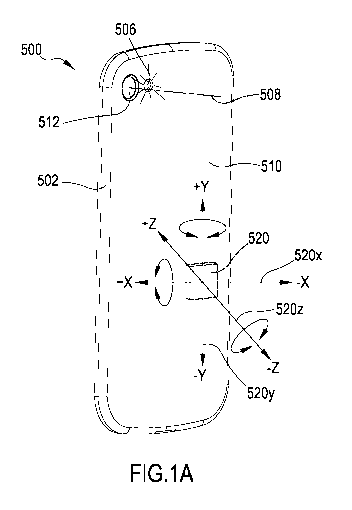
[0037] FIG. 1A illustrates an exemplary mobile device that can be used in
accordance with the method of FIG. 1;
[0038] FIG. 1B illustrates an interaction of a human subject with the mobile
device
shown in FIG. 2;
[0039] FIG. 2 illustrates determining signal quality based on determining a
perfusion index;
[0040] FIGs. 3, 4, and 5 illustrate several steps in determining an SQI based
on
an acquired pulse wave signal;
[0041] FIG. 6 illustrates determining a peak count based on a de-trended pulse
wave signal; and
CA 03063950 2019-11-18
WO 2018/210985 PCT/EP2018/062841
9
[0042] FIGs. 7A and 7B illustrate determining signal quality based on
performing
a peak count.
Detailed Description
[0043] FIG. 1 contains a flow chart of a method 100 for recording pulse wave
data
in accordance with the present invention, using a mobile device having
video recording capabilities. Mobile communication devices, in particular
so-called smart phones, have extensive capabilities beyond mere
telecommunication. For example, most mobile phones are typically
provided with a digital camera capable of capturing still images and video
and with a corresponding light source for low-light situations. Generally, a
pulse wave can be recorded by detecting, with an optical sensor, light
emitted from a light source and reflected by a finger of a subject. In one
embodiment, pulse wave data is obtained using a common mobile device
equipped with a digital camera (e.g. used as an optical sensor) and an
LED light (e.g. used as a light source). The light emitted by the light source
is reflected, for example from tissue of a finger placed on the optical
sensor and the light source, and the properties of the light (e.g. intensity,
hue, brightness, saturation) are affected (e.g. modulated or changed) by
acral blood flow in the finger.
[0044] Recording pulse wave data in this manner, however, is prone to
measurement errors, for example when a subject moves their finger or the
device, or when a subject otherwise changes the relative position of the
finger and/or the device used. Since the optical measurements are based
on very small changes of optical properties of the reflected light (or light
permeating through the tissue), already minor changes to measurement
parameters may greatly impact the quality of the measurements. For
example, the subject could alter a pressure of their finger upon the device,
thereby changing an intensity of blood flow through the finger, an intensity
or other property of the light reflected by the finger, and/or a degree of
ingress of the light into the tissue. Any one of these effects may
substantially alter the result of a measurement and, thus, may render
recorded pulse wave data useless for further processing. In other
CA 03063950 2019-11-18
WO 2018/210985 PCT/EP2018/062841
instances, changing a position of the extremity (e.g. lifting the arm or
changing a position of the hand) may also lead to similar effects and, thus,
may render recorded pulse wave data useless for further processing. The
same applies to changes to the relative position of the device and the
finger.
[0045] All the above-mentioned situations typically entail a movement of the
device, for example an acceleration (including, e.g., vibration), translation,
or rotation so that detecting such a movement can provide information on
the reliability of a measurement or a series of measurements. The term
"reliability" is understood to be indicative of fitness or suitability for a
particular purpose. Within the scope of this document, thus, a reliability
signal indicative of a reliability of a signal means that if the reliability
signal
indicates, for a portion of the signal, that the signal is (sufficiently)
reliable,
then it can be assumed that the data the (portion of the) signal is
pertaining to is (sufficiently) accurate and/or that processing the data the
(portion of the) signal is pertaining to will render (sufficiently) accurate
results. It is understood that reliability includes any predetermined quality
or property indicative of fitness or suitability for a particular purpose.
Further, reliability may be quantified as desired, for example by mapping to
a series of discrete values (e.g. "good", "bad"), a range of values (e.g.
integers from 1 to 10, decimal values such as [0.0,...,1.0], etc.), or any
other (numeric) representation allowing for further processing.
[0046] Method 100 includes two processes, which are performed substantially
simultaneously. The first process (see steps 102' and 116') is performed in
order to acquire a reliability signal indicative of a signal quality of the
pulse
wave signal. The second process (see steps 102 to 116) is performed in
order to acquire an original pulse wave signal, which forms the basis for
further processing. The reliability signal may include a continuous signal or
a series of discrete values over time. In both cases, a reliability value can
be determined for any time point, either from the continuous signal or from
one or more discrete values (e.g. by interpolation). The two processes are
described below.
CA 03063950 2019-11-18
WO 2018/210985 PCT/EP2018/062841
11
[0047] In the first process, at step 102', data from an accelerometer 520 (see
FIG.
1A) is acquired. The accelerometer data may include one or more of
acceleration data (e.g. along one or more of an X, a Y, and a Z axis of the
mobile device and/or of the accelerometer), movement data (e.g. along
one or more of the X, Y, and Z axes), and rotation data (e.g. about one or
more of an X, Y, and Z axes).
[0048] In one embodiment, accelerometer data is acquired in form of a three-
dimensional vector, the vector including acceleration data along the three
axes X, Y, and Z. In some embodiments, the accelerometer data may be
acquired in form of an n-dimensional vector, the vector including one or
more of acceleration, movement, and rotation data.
[0049] In the embodiment, in which the accelerometer data is acquired in form
of
three-dimensional vectors, the acceleration data includes a plurality of
three-dimensional vectors. Each vector is provided with a time stamp
allowing to relate another time-stamped value or measurement (e.g. a
measurement of a parameter made a point in time covered by the plurality
of vectors) to a respective vector.
[0050] In step 116' a reliability signal is obtained based on the acceleration
data.
The acceleration data may be processed in a weighted manner, wherein
acceleration data pertaining to a particular axis (e.g. X, Y, or Z) may be
weighted differently from other axes. In this manner, the acceleration (or
movement, or rotation) along one axis may be regarded as more (or less)
detrimental to any measurements made and, thus, be weighted with a
higher (or lower) factor.
[0051] Further, a single magnitude may be obtained for each three-dimensional
vector of the plurality of vectors, in order to obtain a single time-stamped
value for each vector. This may include calculating a square root based on
each vector. This may further include disregarding (single) outliers, which
may be inherent to the measured accelerometer data. It is noted that the
respective equation, based on which an acceleration value is determined,
may depend on, for example, the type of device used. Some devices are
provided with standard accelerometers, while some other devices are
equipped with more complex integrated sensors, for example integrating
CA 03063950 2019-11-18
WO 2018/210985 PCT/EP2018/062841
12
an accelerometer, a magnetometer, and/or a gyroscope. Depending on
the respective components of a device, a different corresponding method
may be employed in order to determine an acceleration value.
[0052] In one embodiment, a single acceleration value is determined based on
an
integrated sensor (including an accelerometer, a magnetometer, and a
gyroscope), which provides three acceleration values XAcc, YAcc, and zAcc.
The three values are determined at regular intervals, for example once per
second, and a value userMotion indicative of a motion induced by a user
of the device based on the equation: userMotion = IXj
cc + Acc zilcc *
9.81 ; . This value is provided with a timestamp and stored in a memory
unit.
[0053] In another embodiment, a single acceleration value is determined based
on an accelerometer only, which provides three acceleration values XAcc,
YAcc, and Zacc. The three values are determined at regular intervals, for
example once per second, and a value userMotion indicative of a motion
induced by a user of the device based on the equation: userMotion =
X,24c.c. yi24c.c. Zi24c.c. ¨ 9.81 11 . This value is provided with a timestamp
and stored in a memory unit.
[0054] In order to determine the reliability data from the accelerometer data,
the
accelerometer data, or the modified accelerometer data, are compared to
a predetermined threshold value. If the value of the acceleration exceeds
the predetermined threshold value, a respective reliability value for the
time point corresponding to the time stamp of the accelerometer data
exceeding the predetermined value is set to a value associated with the
status "unreliable" (e.g. a numerical value, such as "0"). In this manner, the
values of the pulse wave data measured or recorded substantially at the
same time point can be discarded based on a corresponding reliability
value. The reliability data include time-stamped reliability values. A
reliability value may include an integer (e.g. 0 = unreliable, 1 = reliable)
or
a decimal value (e.g. ranging from 0.0 to 1.0, thereby expressing different
reliabilities; 0.7 could, thus, be considered relatively reliable). It is
noted
that any quantitative (e.g. numeric value, values, value range or ranges) or
CA 03063950 2019-11-18
WO 2018/210985 PCT/EP2018/062841
13
qualitative (e.g. predefined categories, states, or properties) representation
may be used in order to define a reliability of the signal.
[0055] The above-described embodiment realizes a localized determination of
acquired pulse wave data being considered reliable or unreliable. This
means, that for each record or data set, a record or data set pertaining to a
certain time point, it can be determined whether the record or data set is
reliable or unreliable, based solely on a corresponding reliability value
associated to the respective time point and without taking into account
reliability values determined in adjacent time periods (e.g. before or after
the time point). In some embodiments, the reliability values may be
averaged over a period of time in order to, for example, filter out outliers
or
measurement artifacts. In such embodiments, the reliability values may be
further be based on interpolated values in order to be able to provide an
averaged and/or interpolated reliability value for any point in time ¨ not
just
respective time points for which accelerometer data has been acquired.
[0056] In the second process, at step 102, the subject places their finger on
the
camera of the mobile device, preferably without touching the light source,
such that light emitted from the light source illuminates the acral blood flow
and is reflected or dispersed and subsequently detected by the camera.
The video signal thus created is recorded and stored in a memory unit of
the device. Alternatively, the video signal (e.g. a video stream) can be
processed directly, without necessitating storing the pulse wave data in a
memory unit. With respect to step 102, it is noted that in some
embodiments, an external light source can be used, such that the mobile
device need not be provided with a corresponding light source. Such
embodiments may be based on an external (artificial or naturally
occurring) light source (e.g. an external lamp or sunlight).
[0057] In the embodiment described with respect to FIG. 1, the mobile device
is a
mobile phone provided with a camera and a corresponding light source. In
alternative embodiments, the mobile device may be a different device and
such different device may be in contact with tissue of a human subject in
another manner. For example, the mobile device may include a so-called
smart watch provided with an optical sensor and a light source. The light
CA 03063950 2019-11-18
WO 2018/210985 PCT/EP2018/062841
14
source may be configured to illuminate the tissue of a human subject (e.g.
tissue in the region of the wrist of a human subject) and the optical sensor
may be configured to detect light reflected from (or permeating through)
the tissue in the region of the wrist of the human subject. Irrespective of
the individual embodiment, the mobile device may be configured to detect
light reflected from (or permeating through) tissue of a human subject,
including thumbs or fingers, arms, wrists, ankles, ears, nasal septum, and
the forehead of a human subject.
[0058] In step 104, a region of interest (ROI) is selected from the full
resolution
video stream. This selection can be performed, for example, based on
brightness information contained in the video stream. In one embodiment,
the ROI is determined in a region of maximum brightness within a video
frame, off the center and at a minimum distance from the border. This can
ensure that a region is chosen that is sufficiently illuminated (e.g. a region
close to the light source). In one embodiment, the ROI has a size of at
least 50 x 50 pixels (i.e. 2500 square pixels). Generally, the ROI can have
a size ranging from 625 to 10000 square pixels, preferably 900 to 6400
square pixels, more preferably 1600 to 3200 square pixels.
[0059] In step 106, for the ROI of each frame of the video stream, a samples,
is
calculated, based on
N-1 M-1
p(j = w + k)
si ¨
2
j=0 k=0
with p being the value of the green channel of the pixel located within the
ROI at the position j,k; N and M being the size of the ROI; and w being the
width of the ROI. The division by 2 eliminates the lowest Bit of p, such that
noise is effectively reduced. This produces a sample s, for each captured
video frame.
[0060] In step 108, a time stamp t is generated for each sample 5, (more
accurately, for each video frame, based on which the sample was
calculated) and encoded into the video stream by the video camera. The
same time stamp t, is used in generating the reliability signal. Determining
the pulse wave and the measurements based on which the reliability
signal is generated, is preferably performed substantially simultaneously.
CA 03063950 2019-11-18
WO 2018/210985 PCT/EP2018/062841
[0061] In step 110, the pulse wave is obtained as a pulse wave signal based on
the samples s, obtained in step 106.
[0062] In step 112, a re-sampled pulse wave is obtained by re-sampling the
pulse
wave from the samples Si (i.e. as obtained in step 110) based on the
associated time stamps obtained in step 108. This is necessary due to
technical issues in detecting, generating, and encoding video data, for
example resulting in dropped frames or non-constant frame rates. Based
on these issues, the samples Si cannot be obtained at fixed and reliable
time intervals. In order to obtain the re-sampled pulse wave, the pulse
wave is re-sampled using a cubic spline interpolation and is performed on
each polynomial. Here, two subsequent samples are interpolated by a
third-degree polynomial. The position (in time) of the samples corresponds
to the time stamps. The polynomial S, for the range [t,,t,,i] is calculated as
follows:
Si = ai + bi(t ¨ t32 + di(t ¨ ti)3
with i= 1, ..., n-1. The process of re-sampling includes incrementing t
continuously by 1 ms, corresponding to a sample rate of 1000 Hz. The
parameters a,, 1)1, ch and d, have to be set to suitable values. The pulse
wave is obtained as the signal S being the result of the re-sampling.
[0063] In step 114, the re-sampled pulse wave is filtered to eliminate noise
and to
compensate for drift. This can be achieved by applying a common band-
pass filter (e.g. 0.1 to 10 Hz).
[0064] In step 116, the original pulse wave signal is obtained as a basis for
further
processing. When the second process ends, for example when a desired
pulse wave signal has been obtained, also the first process ends, so that
the reliability signal obtained in the first process pertains to substantially
the same time period as the pulse wave signal obtained in the second
process.
[0065] FIG. 1A illustrates an exemplary mobile device that can be used in
accordance with the method of FIG. 1. The mobile device 500 has a frame
or main body 502 and a device panel 510. In some examples, the device
panel 510 can be a back panel of the mobile device 500. The device 500
further has a camera device 512 capable of detecting digital video signals,
CA 03063950 2019-11-18
WO 2018/210985 PCT/EP2018/062841
16
for example in the form of digital still images and digital video. The camera
device 512 is configured to detect video signals representative of objects
located generally with a frustum-shaped region along a main detection
direction 508. The device 500 further has a light source 506 configured to
illuminate any objects located in front of camera device 512, i.e. located
within the frustum-shaped region and/or along a main detection direction
508.
[0066] Mobile device 500 further comprises a light source 506. The light
source
506 can be configured to provide both a single flash of light and a
continuous light beam, depending on a mode of operation. When
recording video, the light source typically provides a continuous light
beam. An object placed within the view of camera device 512 will reflect
and/or diffuse light emitted from light source 506, so that the reflected
light
can be detected by camera device 512.
[0067] Mobile device 500 further comprises a control unit (e.g. a CPU, micro
processor, SoC; not shown) coupled to other components, such as
camera device 512, light source 506, a memory unit, a user interface,
input means, an audio unit, a video unit, a display, and other.
[0068] Mobile device 500 further comprises a sensor, typically an
accelerometer
or other type of sensor configured for detecting a physical parameter, for
example including acceleration, motion, rotation, and orientation. Typically,
the sensor includes an accelerometer 520. However, the sensor may
further or alternatively include any sensor configured to detect
acceleration, motion, orientation and/or rotation. Thus, the motion sensor
may include an accelerometer 520, a magnetometer, a gyroscope (or
gyro), or other sensor configured to detect acceleration, motion, orientation
and/or rotation. Suitable sensors are typically provided in the form of
micro-electromechanical systems or MEMS.
[0069] A magnetometer may be configured to detect a magnetic field, for
example
the magnetic field of the earth. The signal generated by a magnetometer
may be used in order to detect acceleration, motion, orientation and/or
rotation of an associated device.
CA 03063950 2019-11-18
WO 2018/210985 PCT/EP2018/062841
17
[0070] An accelerometer may be configured to detect proper acceleration (as
opposed to coordinate acceleration), i.e. absolute acceleration, such that
an accelerometer resting on a fixed surface may detect acceleration due to
the earth's gravity in direction of one or more of its axes, depending upon
an orientation of the accelerometer. Thus, an orientation of the
accelerometer may be determined based on the acceleration detected due
to changes in the direction of the earth's gravity. The signal generated by
an accelerometer may, thus, be used in order to detect acceleration,
motion, orientation, and/or rotation of an associated device.
[0071] A gyroscope may be configured to detect movement in terms of
acceleration and/or rotation. The signal generated by a gyroscope may be
used in order to detect acceleration, motion, orientation and/or rotation of
an associated device.
[0072] In the embodiments described, the mobile device 500 is provided with an
accelerometer 520. However, embodiments of the present invention may
be based on the mobile device being provided with an accelerometer 520
as described and/or on one or more sensors (e.g. including one or more of
a magnetometer, a gyroscope, an accelerometer, or other sensor as
described above) configured for detecting acceleration, motion, orientation
and/or rotation of the mobile device 500, thus, not limiting the inventive
concepts on the mobile device being provided with an accelerometer 520.
Accelerometers are typically available as single- or multi-axis
accelerometers and enable the detection of magnitude and direction of
proper acceleration, as a vector quantity.
[0073] In the embodiment shown in FIG. 1A, mobile device 500 is provided with
an accelerometer 520 configured to detect acceleration along three axes,
namely an X-axis 520x, a Y-axis 520y, and a Z-axis 520z. The directions
of the axes 520x, 520y, and 520z, as well as a polarity thereof (i.e.
defining which direction, e.g., denotes +X and which -X) may differ from
what is shown in FIG. 1A, and the type, position, and orientation of
accelerometer 520 within mobile device 500 may vary. In other
embodiments, other accelerometers may be used, for example
accelerometers having more or less axes.
CA 03063950 2019-11-18
WO 2018/210985 PCT/EP2018/062841
18
[0074] Typically, mobile devices are provided with a single accelerometer 520.
In
some embodiments, mobile devices may be provided with two or more
accelerometers. For example, it might be desired to provide mobile device
500 with a first accelerometer that provides a first accuracy, detection
range, resolution, and/or number of detection axes, and with a second
accelerometer that provides a second accuracy, detection range,
resolution, and/or number of detection axes different from the first. In such
examples, the first (or second) accelerometer may offer a lower power
consumption as compared to the other, so that one of the first and second
accelerometers may be selected based on a use configuration of the
mobile device. It is noted that embodiments of the present invention may
be based on any accelerometer that is configured to detect acceleration,
irrespective of accuracy, detection range, resolution, and/or number of
detection axes. Preferred embodiments, however, are based on
accelerometers having at least three axes of detection.
[0075] FIG. 1B illustrates an interaction of a human subject with the mobile
device
shown in FIG. 1A. In order to take a measurement, the subject places a
finger (e.g. a thumb) on mobile device 500, covering both the camera
device 512 and the light source 506. The individual configuration of the
mobile device (e.g. a position of camera device 512 and light source 506
or the distance in between) is of secondary relevance, as long as it is
physically possible to cover both the camera device 512 and the light
source 506 with a suitable extremity (e.g. finger, thumb, ear). In this
respect, any extremity suitable for (acral) measurement can be used in
accordance with the present invention. In general, any body part that is
associated with pulsating blood flow can be used in accordance with the
present invention, as long as a meaningful signal indicative of the blood
flow can be detected via the body part of a subject (e.g. fingers, arms,
wrists, ankles, ears, nasal septum, or forehead).
[0076] In some embodiments, the control unit of mobile device 500 will process
signals provided by camera device 512 and detect, based on the signals
provided, that one or more parameters indicative of video quality (e.g.
brightness, contrast, focus) are outside of preferred operating ranges due
CA 03063950 2019-11-18
WO 2018/210985 PCT/EP2018/062841
19
to a low-light and/or close-proximity situation created by the placement of
the thumb directly onto camera device 512. The control unit may then
provide control signals to one or more components, for example to light
source 506, in order to make adjustments to the parameters (e.g.
activating light source 506 in order to compensate for low light).
[0077] Upon placement of the suitable extremity (here, e.g., the thumb of the
subject), the measurement is initiated by activating the light source 506 to
emit a continuous light beam of sufficient intensity, such that acral blood
flow is illuminated. At substantially the same time, camera device 512 is
activated and the light reflected by the acral blood flow is detected by
camera device 512. Both activating the light source 506 and activating the
camera device 512 can be achieved by corresponding program code
executed by the control unit comprised in device 500.
[0078] The activation can be triggered manually, for example by selecting a
corresponding function on a user interface of device 500, or automatically,
for example triggered by a sensor (e.g. a proximity sensor, an optical
sensor), a timer, voice recognition, or other (input means). In one example,
the signal of the sensor is continuously processed to check for the
presence of a suitable signal. Video data is then recorded or transmitted
for further processing for a predetermined period of time, typically ranging
from several seconds to 5 minutes. In preferred embodiments, the
predetermined period of time ranges from 1 minute to 5 minutes, more
preferably the predetermined period of time is about 1 minute, about 3
minutes, or about 5 minutes. Selecting such predetermined time periods
allows for a reliable determination of a subject's heart rhythm.
[0079] In some alternative embodiments, the time period is not predetermined,
but determined as the recording/transmitting is ongoing, in that a quality
measure is calculated from the recorded/transmitted data and the
recording/transmitting is performed until a sufficient number of heart
periods (e.g. 60-400) of sufficient quality (see further details below) has
been recorded/transmitted, in order to determine a subject's heart rhythm.
Completion of the recording/transmitting can be indicated to the subject,
CA 03063950 2019-11-18
WO 2018/210985 PCT/EP2018/062841
for example, by an acoustic and/or optical signal emitted by an audio
and/or video component of device 500.
[0080] At substantially the same time, the control unit is configured to
acquire
accelerometer data from the accelerometer 520, the accelerometer data
being indicative of one or more of an acceleration, an orientation, a
motion, and a rotation of accelerometer 520, and, thus, of mobile device
500.
[0081] It is noted that other embodiments employ the same or different sensors
and/or devices. For example, smart watches having a corresponding light
source/sensor assembly as described above with respect to FIGs. 1A and
1 B, can be used as well. These devices have an advantage in that the
sensor is kept in close proximity to the body (here, e.g. the wrist) of a
subject, thereby facilitating continuous measurements and/or
measurements of arbitrary duration and at arbitrary time points, without
interaction of a subject (e.g. also during sleep). It is noted that the above
concepts apply to a range of sensors and are not limited to a particular or
otherwise specific embodiment of sensor hardware.
[0082] As described above, acquiring the pulse wave signal and the reliability
signal allows for determining whether the pulse wave signal is reliable,
based on the reliability signal. Therefore, the combination of the pulse
wave signal and the reliability signal is already inherently reliable. Also,
the
control unit 530 may be configured to determine a verified pulse wave
signal based on the pulse wave signal and the reliability signal, for
example including discarding the pulse wave signal for a respective time
period, if the reliability signal indicative of the reliability of the pulse
wave
signal for the respective time period is not within a predetermined range
(or below a predetermined threshold value). The pulse wave signal being
discarded would, thus, indicate that the pulse wave signal is not regarded
as reliable and/or indicate that there is a high probability of the pulse wave
signal containing artifacts or otherwise being inaccurate.
[0083] However, other, alternative, or additional methods can be applied in
combination with the above-described method for obtaining a reliable
signal in order to further improve the reliability and/or quality of the
signal,
CA 03063950 2019-11-18
WO 2018/210985 PCT/EP2018/062841
21
and/or in order to avoid recording of a compromised signal. In the
following, three further methods are described, which can be combined
with the above-described method for obtaining a reliable signal in any
combination of the three methods.
[0084] The first method is based on determining a correlation of subsequent
heart
periods and on determining signal quality based on whether the
determined correlation is below a minimum correlation value. To this aim,
an original pulse wave signal is typically pre-processed. Pre-processing
may involve one or more of determining a trend and subsequently de-
trending the original pulse wave (see below with respect to the second
method), applying a low-pass filter, and determining heart periods.
[0085] Determining a trend and de-trending the original pulse wave may include
observing a running window of three subsequent heart periods calculating
non-pulsatile blood as the statistical mean over the running window. This
is described in more detail below with respect to FIG. 2. As a result, a
trend is obtained, which represents low frequency variations of the original
pulse wave. Additionally or alternatively, a low-pass filter may be applied in
order to filter out unwanted frequencies that are outside of frequencies of
interest (e.g. outside of a range of 0.5 Hz to 7 Hz). A low-pass filter can
substantially attenuate or eliminate frequencies above a predetermined
frequency, for example above 3 Hz. Heart periods are typically determined
by determining inflection points in the original pulse wave.
[0086] Optionally, in order to determine the correlation of subsequent heart
periods, each of a selected number of periods may be normalized into an
interval of y-values between 0 and 1. In one embodiment, a window of
three subsequent heart periods is observed. Generally, using larger
windows may increase specificity while using smaller windows may
increase sensitivity. The correlation of the three subsequent heart periods
is based on a pairwise comparison of the (normalized) periods (e.g. 1-2, 1-
3, 2-3) and on determining a similarity score for each pair (localized
similarity). Next the maximum of the resulting correlation coefficients is
determined and compared to a threshold value. If the maximum correlation
coefficient is below the threshold value, the original pulse wave, for the
CA 03063950 2019-11-18
WO 2018/210985 PCT/EP2018/062841
22
respective heart periods (or for the respective three heart periods) can be
discarded or disregarded as being of insufficient quality.
[0087] The second method is based on determining a perfusion index using a
running window over subsequent heart periods. The perfusion index is the
ratio of the pulsatile (AC) blood flow to the non-pulsatile (DC) or static
blood in peripheral tissue. In other words, it is the difference of the amount
of light absorbed through the pulse when light is transmitted through the
finger. Signal quality is determined based on a ratio of AC and DC, a
smaller ratio being indicative of a signal of lesser quality.
[0088] FIG. 2 illustrates determining signal quality based on determining a
perfusion index. The diagram 360 depicted in FIG. 2 shows several graphs
362, 364, and 366 illustrating the second method. Diagram 360 illustrates
the amplitude of signal (see vertical axis) over time (see horizontal axis).
Graph 362 is indicative of the original pulse wave signal. In one
embodiment, a running window of three or more subsequent heart periods
is observed and DC is calculated as the statistical mean over the running
window. In other embodiments, windows of a different size can be
observed, in particular windows having a size of three or more heart
periods. Subsequent values of DC determine a trend of the signal, shown
in diagram 360 as graph 364. As can be seen, the trend is interpolated in
order to provide a continuous signal. Based on the original pulse wave 362
and the trend 364, a de-trended and filtered pulse wave signal 366 is
determined. In order to determine the quality index, c is calculated as
krnax¨
min , with Amax and Amin respectively corresponding to the maximum
and minimum values of signal 366 within a single heart period, and )7
corresponds to the value of the trend 364 for the heart period, as
previously determined for the pulse wave signal 362. In order to determine
whether the pulse wave signal for a particular heart period fulfills quality
requirements, the ratio c is compared to a threshold value. If the ratio is
below the threshold value, the pulse wave signal for the heart period in
question is not of sufficient quality.
[0089] The third method is based on determining respective maxima in the
frequency spectrum of a pulse wave signal, when observing a running
CA 03063950 2019-11-18
WO 2018/210985 PCT/EP2018/062841
23
window of three subsequent heart periods. The method is based on a
Fourier Transformation (e.g. an FFT based on a Nanning window) and
includes determining respective maxima in the resulting frequency
spectrum. The frequency spectrum of a pulse wave signal of good quality
will exhibit few peaks and significant (i.e. well visible) harmonic waves
without secondary peaks. If the frequency spectrum suffers from a large
number of peaks, this indicates that the original pulse wave is of low
quality due to several frequencies dominating the spectrum.
[0090] FIGs. 3, 4, and 5 illustrate several steps in determining an SQI based
on
an acquired pulse wave signal. In general, determining the SQI is based
on maintaining a buffer of size w, which stores samples of an acquired
pulse wave along with corresponding time stamps. The buffer is typically
implemented as a ring buffer, corresponding to a moving window of the
size w. The example shown in FIGs. 3, 4, and 5 is based on a window size
W = 6 = FS, wherein FS is the sampling rate. The horizontal axis in each
diagram shows time in milliseconds (ms) and the vertical axis shows the
sample value.
[0091] FIG. 3 (a) shows an unprocessed raw signal, which is generated based on
the sample values and the associated time stamps. Then, as shown in
FIG. 3 (b), the initial time stamp is set to zero, so that the signal is reset
in
time. Further, the signal is re-sampled based on cubic splines using a
sampling rate of 50 Hz in order to ensure that the signal has exhibits
equidistant sampling. In detail, the cubic spline approximation results in
each two subsequent samples being approximated using a 3rd order
polynomial. The relative position (in time) of the samples corresponds to
the respective time stamps. The polynomial S, in the range [t,,t,+/] is
determined based on Si = ai + bi(t ¨ ti) + ci(t ¨ ti)2 + di(t ¨ t)3, with i =
1, ...,N ¨ 1. In accordance with the re-sampling rate of 50 Hz, t is
continuously incremented by 20 ms. Parameters a, b,, c,, d, must be
determined in a suitable manner. The signal shown in FIG. 3 (b) forms the
basis for the following processing steps.
[0092] FIG. 3 (c) illustrates the signal after normalization (e.g. zero-mean,
optionally with unit variance; see different range of values on the vertical
CA 03063950 2019-11-18
WO 2018/210985
PCT/EP2018/062841
24
axis in FIG. 3 (b) as compared to FIG. 3 (c)). Subsequently, the signal is
de-trended, see FIG. 3 (d). To this aim, a Gaussian low-pass filter is
applied in order to filter the signal and to find a trend, based on Si = S, ¨
with i = 0, ...,n ¨ 1, and based on g = 1E7i1=01-Si. FIG. 3 (d) illustrates
the
original signal and the trend determined from the signal. As illustrated in
FIG. 3 (e), the trend is subtracted from the original signal based on Si =
¨ tri), with i = 0, ...,n ¨1, tr, corresponding to a respective sample
point in the trend signal. Further, the signal is inverted (see FIG. 3 (e)).
[0093] In order to find periods, the positive maxima of the 1st order
derivative of
the de-trended signal are determined. These positive maxima correspond
to the inflection points in the rising edges. Determining the 1st order
derivative may be achieved based on the algorithm of Savitzky-Golay,
which causes a simultaneous smoothing of the derivative, as illustrated in
FIG. 3 (f). The boundaries may be expanded by padding (see FIG. 4(a) for
the left boundary and FIG. 4(b) for the right boundary). It is noted that the
horizontal axis in FIGs. 3 (f), 4 (a), et seq. shows the sample index and,
thus, effectively sets the unit size to 20 ms (based on the sample rate of
50 Hz). Smoothing and the 1st order derivative are calculated using the
Savitzky-Golay filter: Yi = E 2 L. Tri_i CiSi_i, with 71'1- < j < n
Further,
2
2
j = 1, ..., n, wherein n is the number of sampled points. C, denotes the
convolution kernel and, here, C = (-3, ¨2, ¨1,0, 1,2, 3). Further, m is the
number of coefficients of the convolution kernel (here, m=7). In order to
provide point at either end, the signal is continued, wherein 711- points
2
have to be expanded at both ends (see FIG. 4 (a) and (b)): S_i = 2S0 ¨ Si
and Sn_i_Fi = 2Sn_i ¨ with i = 1, ...,4. Negative indices of S and
indices larger than n ¨ 1 are indicative of the expansion of the signal.
FIG. 4 (c) illustrates the original signal, the padded signal, and the 1st
order derivative of an illustrative example.
[0094] In order to determine the periods, all positive maxima of the 1st order
derivative have to be identified (see FIG. 4 (d)). Subsequently, the
identified maxima are sorted by value, largest first, in descending order.
Then 25% of both the largest and smallest values are discarded and mean
CA 03063950 2019-11-18
WO 2018/210985 PCT/EP2018/062841
value of the remaining 50% is determined. One third of the mean value is
then taken as a threshold value for maxima of the 1st order derivative and
all maxima exceeding this threshold value are taken into account when
marking the beginning of the periods (see FIG. 4 (e)). Each period is
enclosed between two subsequent maxima of the 1st order derivative (see
FIG. 4 (0).
[0095] From the periods determined as described above, the last three periods
are selected for a comparison step (see FIG. 5 (a)). In this comparison
step, each of the three selected periods is compared with the two other
periods (i.e. 1-2, 1-3, 2-3; see FIG. 5 (b)) and a correlation (or similarity)
value is determined using a cross correlation function (see FIG. 5 (c)),
wherein temporal lag is disregarded. Out of the three determined
correlation values, the maximum value is taken as being indicative of the
similarity for the respective window. The normalized cross correlation can
be determined as follows. With x and y being the periods to compare, the
length of the periods is assumed as being 64 units (longer periods are cut
fF-1-Vfxl*Ffyr11
and shorter periods are padded accordingly): kxy = max( 11x11211Y112
with F being the FFT of fixed length, * being the conjugate. Consequently,
the similarity value of the window is SQIõõ = max{k12, k13, k23}.
[0096] The beginnings of the periods determined in the comparison step, i.e.
the
inflection points as illustrated in FIG. 5 (a), form the basis for determining
the perfusion index. Each of these points marks the rising flank of the
periods and for each of these points, the previous maximum (i.e. to the left
of the respective point) and the following maximum (i.e. to the right of the
point) are determined, as shown in FIG. 5 (d) and (e). The inflection point
is then projected into the original pulse wave (before de-trending), which
provides the estimate for the DC (i.e. the non-pulsatile blood flow), as
illustrated in FIG. 5 (0. In order not to let the DC range get too small, a
minimum value of 1000 is set. The following equation determines the
perfusion index for a period i: perfldxi = . Subsequently, the mean
value perfldx of the mid 50% of the ordered values (see above; upper
and lower 25% are disregarded) is determined as the overall perfldx:
SQlperf index = 100 ' perfldx.
CA 03063950 2019-11-18
WO 2018/210985 PCT/EP2018/062841
26
[0097] FIG. 6 illustrates determining a peak count based on the de-trended
pulse
wave signal. The de-trended signal forms the basis for determining the
number of dominant frequencies. The frequency spectrum is generated
based on the following equation, with N being the length of the signal and
IFtS=hanning(N1. Here, S is multiplied
NFFT the next power of two: sp =
I NFFT
with the Nanning window of length N. Subsequently, the vector is set to
length NFFT by zero padding. Over this vector, the FFT is generated and
normalized (see FIG. 6 (a) and (b); diagram (a) shows the de-trended
signal and diagram (b) shows the corresponding frequency spectrum).
[0098] In order to determine the heart rate from the frequency spectrum, a
frequency region is defined, in which the highest peak is determined (see
FIG. 6 (c) and (d)). The frequency of the highest peak corresponds to the
current heart rate (see FIG. 6 (e) and (0). The frequency region (or search
region) is defined as 0.6 Hz to 3.0 Hz.
[0099] In order to determine the number of dominant frequencies, the spectrum
sp is examined for all occurring peaks idx (see FIG. 6 (g) and (h)), with idx
corresponding to the indices of the peaks in the spectrum: sp(idx) =
sp(idx)
. Each peak is divided by the sum of all peaks. The threshold
Etdx SP (idX)
value based on which the remaining peaks are separated is determined
as: thr = sP(icixmax) 500 ,with idxMax corresponding to the index of the
highest
peak. All peaks larger than the threshold value thr are taken into account
when determining the number of the dominant frequencies (see FIG. 6 (i)
and (j)): SQlpeakcount = 44(SP(idx) > thr). The overall SQI is then
determined from the discriminant analysis of the three parameters. An
example SQI determined from an example data set was determined as:
SQI = 3.47723899802885 =SQ/coõ ¨ 0.125428815152482 SQlpeakcount
0.408789084581875 SQlperf index + 0.920673015347965.
[00100] Typically, the values determined based on the above discriminant
function
has to be mapped onto the interval (0,1). Based on this, an indicator can
be determined as a visual tool for estimating signal quality. Possible
candidate include, but re not limited to, linear mappings or n-th-order
polynomials focusing on individual regions separately.
CA 03063950 2019-11-18
WO 2018/210985 PCT/EP2018/062841
27
[00101] It is noted that depending on respective implementations of the
process
(e.g. depending on the devices and/or operating systems used), individual
discriminant functions and/or mappings may have to be provided. Further,
the parameter / SO
--peakcount does not take into account the current heart
frequency.
[00102] FIGs. 7A and 7B illustrate determining signal quality based on
performing
a peak count. As described above, a Fourier Transformation is performed
and provides a frequency spectrum, for example, as shown in FIGs. 7A
and 7B. Each diagram shows the frequency spectrum as FFT (see vertical
axis) over frequency (see horizontal axis; Hz). FIG. 7A illustrates a
resulting frequency spectrum indicative of an original pulse wave of low
quality. Diagram 300 in FIG. 7A shows the resulting graph 310 and
respective minima 314 and maxima 312. As can be seen from FIG. 7A, the
graph 310 exhibits a number of peaks, for example, about eight peaks in
the frequency band below 5 Hz and a similar number for the frequency
band from 5 Hz to 10 Hz. A comparatively high number of peaks indicates
that the original pulse wave for the three heart periods observed was of
low quality.
[00103] As a comparative example, FIG. 7B illustrates a resulting frequency
spectrum indicative of an original pulse wave of high quality. Diagram 300
in FIG. 7B, again, shows the resulting graph 310 and respective minima
314 and maxima 312. As can be seen from FIG. 7B, the graph 310
exhibits a smaller number of peaks as compared to FIG. 7A. In the
comparative example of FIG. 7B, graph 310 exhibits only about four peaks
in the frequency band below 5 Hz and a similar number for the frequency
band from 5 Hz to 10 Hz. A comparatively low number of peaks indicates
that the original pulse wave for the three heart periods observed was of
high quality.
[00104] While the invention has been described in connection with what is
presently considered to be the most practical and preferred embodiments,
it is to be understood that the invention is not to be limited to the
disclosed
embodiments, but on the contrary, is intended to cover various
CA 03063950 2019-11-18
WO 2018/210985
PCT/EP2018/062841
28
modifications and equivalent arrangements included within the spirit and
the scope of the appended claims.