Note: Descriptions are shown in the official language in which they were submitted.
CA 03064065 2019-11-18
WO 2019/147784 PCT/US2019/014920
FOOD LOG SLICING APPARATUS FOR SLICING
MULTIPLE LAYERS OF STACKED FOOD LOGS
[001] This application claims the domestic benefit of United States
Provisional Application
Serial No. 62/622,449, filed on January 26, 2018, the contents of which are
incorporated herein
in its entirety.
FIELD OF THE INVENTION
[002] The present disclosure generally relates to a food log slicing apparatus
for slicing
multiple columns of food logs at the same time.
BACKGROUND
[003] Food product slicing machines have existed for some time and are used to
slice various
food products at a high-speed rate. Exemplary food products include meat, such
as beef,
chicken, fish, pork, etc., and cheese. Various deficiencies have been
identified with such food
product slicing machines.
SUMMARY
[004] A need exists for a food log slicing apparatus that resolves
deficiencies of existing food
log slicing apparatus.
[005] In an aspect, a food log slicing apparatus is provided.
[006] In a further aspect, a food log slicing apparatus includes a base, a
frame mounted on the
base, a loaf tray, a drive assembly, a shear bar and a slicing station mounted
on the frame. The
1
CA 03064065 2019-11-18
WO 2019/147784 PCT/US2019/014920
loaf tray and the shear bar are divided into a plurality of side-by-side
lanes, each of which are
configured to receive multiple food logs stacked in a column. Each lane has a
base wall on
which a lowest one of the food logs rests which is angled relative to
horizontal ground. The
drive assembly moves the food logs from the loaf tray to the shear bar and
into the slicing
station. The slicing station has a driven blade which is parallel to a planar
downstream face of
the shear bar, and cuts all of the food logs as the blade passes through the
food logs.
[007] In an aspect, a method of operating a food log slicing apparatus is
provided.
BRIEF DESCRIPTION OF THE DRAWINGS
[008] The organization and manner of the structure and operation of the
disclosed
embodiments, together with further objects and advantages thereof, may best be
understood by
reference to the following description, taken in connection with the
accompanying drawings,
which are not necessarily drawn to scale, wherein like reference numerals
identify like elements
in which:
[009] FIG. 1 is a side elevation view of a food log slicing apparatus;
[0010] FIG. 2 is a perspective view of an input and slicing portion of the
food log slicing
apparatus with food logs mounted thereon;
[0011] FIG. 3 is a side elevation view of the input and slicing portion with
food logs mounted
thereon;
[0012] FIG. 4 is a top plan view of the input and slicing portion with food
logs mounted thereon;
[0013] FIG. 5 is a top plan view of the input and slicing portion without food
logs;
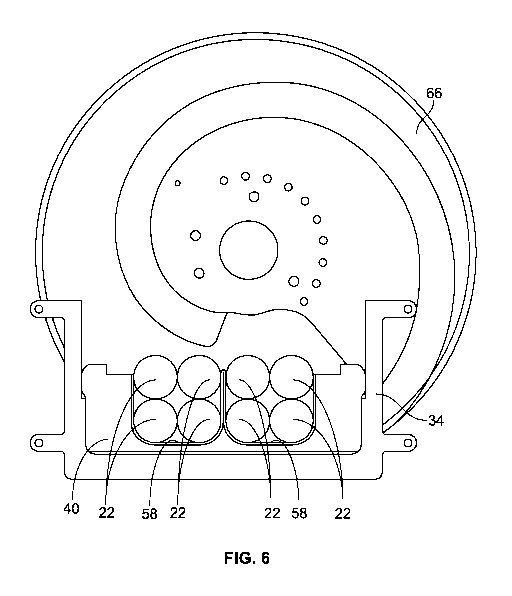
[0014] FIG. 6 is a cross-sectional view along line 6-6 of FIG. 1; and
2
CA 03064065 2019-11-18
WO 2019/147784 PCT/US2019/014920
[0015] FIG. 7 is a front elevation view of a shear bar of the food log slicing
apparatus.
DETAILED DESCRIPTION
[0016] While the disclosure may be susceptible to embodiment in different
forms, there is shown
in the drawings, and herein will be described in detail, a specific embodiment
with the
understanding that the present disclosure is to be considered an
exemplification of the principles
of the disclosure, and is not intended to limit the disclosure to that as
illustrated and described
herein. Therefore, unless otherwise noted, features disclosed herein may be
combined together
to form additional combinations that were not otherwise shown for purposes of
brevity. It will
be further appreciated that in some embodiments, one or more elements
illustrated by way of
example in a drawing(s) may be eliminated and/or substituted with alternative
elements within
the scope of the disclosure.
[0017] A food log slicing apparatus 20 and methods associated with operating
the food log
slicing apparatus 20 are included in the present disclosure. The food log
slicing apparatus 20 and
method have benefits over prior art food log slicing apparatus. With reference
to the figures, one
example of the food log slicing apparatus 20 is shown. The food log slicing
apparatus 20 is used
to slice multiple elongated food logs 22 at the same time into slices. The
multiple food logs 22
may be comprised of a wide variety of edible materials including, but not
limited to meat, such
as pepperoni. In some embodiments, each food log 22 is elongated with a
circular cross-section,
is elongated with a square cross-section, is elongated with an oval cross-
section, is elongated
3
CA 03064065 2019-11-18
WO 2019/147784 PCT/US2019/014920
with a rectangular cross-section, but not limited to these cross-sectional. In
some examples, the
food logs 22 are frozen.
[0018] The food logs 22 are positioned by the food log slicing apparatus 20
such that the foods
logs 22 form a horizontal row of food logs 22 and vertical columns of foods
logs 22. The food
logs 22 are stacked one above the other in the columns, and in side-to-side
orientation in the
rows, to maximize the number of food logs 22 that can be sliced at a time. The
columns of food
logs 22 are separated from each other.
[0019] The food log slicing apparatus 20 includes a base 24 mounted on a
horizontal ground
surface 26, an input and slicing portion 28 mounted on the base 24, an output
portion 30
mounted on the base 24 and downstream of the input and slicing portion 28, and
a control system
32 configured to control operation of the food log slicing apparatus 20. The
control system 32
may be provided on the base 24. The base 24 supports the input and slicing
portion 28, the
output portion 30, and the control system 32 on the ground surface 26 and
includes various
mechanisms and power systems for powering the food log slicing apparatus 20.
The input and
slicing portion 28 is configured to support and handle the multiple food logs
22, to move the
multiple food logs 22, and to slice the multiple food logs 22 into slices. The
slices are supported
on the output portion 30 of the food log slicing apparatus 20 and are moved
away from the input
and slicing portion 28 by the output portion 30. The control system 32
includes all the necessary
hardware and software to perform all of the operations and functions of the
food log slicing
apparatus 20.
4
CA 03064065 2019-11-18
WO 2019/147784 PCT/US2019/014920
[0020] With reference to FIG. 1, the input and slicing portion 28 includes a
frame 34, a loaf tray
36 mounted on the frame 34, a drive assembly 38 mounted on the frame 34 above
the loaf tray
36 and which is moveable relative to the frame 34 and relative to the loaf
tray 36, a shear bar 40
mounted on the frame 34 and which is downstream of the loaf tray 36, a slicing
station 42
mounted on the frame 34 and which is downstream of the shear bar 40. The drive
assembly 38
moves the multiple food logs 22 along the loaf tray 36 such that the multiple
food logs 22 pass
through the shear bar 40 and into the slicing station 42 at the same time.
[0021] The loaf tray 36 is mounted on the base 24 by the frame 34 such that
the loaf tray 36 is
angled relative to a horizontal plane, for example the ground surface 26, at a
predetermined angle
a. In an embodiment, the angle a is 40 degrees, but other angles may be used.
The loaf tray 36
includes walls 44, 46, 48 which form a plurality of separate lanes 50. The
loaf tray 36 incudes
multiple base walls 44 separated from each other by upstanding dividing walls
46 and having
upstanding end walls 48 at the outer ends of the outermost base walls 44. Each
base wall 44
corresponds to a separate lane 50. As shown in the drawings, two lanes 50 are
provided by the
loaf tray 36. The dividing wall(s) 46 and the end walls 48 extend along
substantially the entire
length of the base walls 44. While two base walls 44 and one dividing wall 46
are shown in the
drawings to form two lanes 50, more than two base walls 44 and one dividing
wall 46 may be
provided to form three or more lanes 50. Each base wall 44 has a width which
is approximately
equal to the width of the food log 22 being cut such that the walls forming
the respective lane 50
abut against, or are in close proximity to, the sides of each food log 22 in
the lane 50. In an
CA 03064065 2019-11-18
WO 2019/147784 PCT/US2019/014920
embodiment, each base wall 44 has a length which is less than the length of
the food logs 22.
Since more than one food log 22 is stacked in each lane 50, the walls forming
the respective lane
50 have a height which accommodates multiple food logs 22 stacked on one
another, while
completely separating the individual stacks of food logs 22 in the separate
lanes 50.
[0022] The drive assembly 38 may take a variety of forms and moves the stacks
of food logs 22
to the slicing station 42. In an embodiment, the drive assembly 38 is formed
of multiple grippers
52 which attach to a rear or upstream end of each food log 22 stacked in the
individual lane 50
and which are driven by known means, such as a conveyor belt, to cause the
food logs 22 to slide
along the respective lane 50 in the loaf tray 36. In an embodiment, the drive
assembly 38 is
formed of a driven continuous conveyor belt which engages and presses down
onto the top food
log 22 in each column, and when activated, causes all of the food logs 22 in
the respective
column to slide along the respective lane 50 in the loaf tray 36.
[0023] The shear bar 40 is formed of an elongated wall 54 having a plurality
of separate lanes 56
which are formed by openings 58 in the wall 54 to guide and position the food
logs 22 in the
columns. The wall 54 has an upstream face 54a and a downstream face 54b. At
least the
downstream face 54b is planar. The downstream face 54b is angled relative to
the base walls 44
of the loaf tray 36. In an embodiment, the downstream face 54b is angled at an
angle of 90
degrees relative to the base walls 44 of the loaf tray 36. The lanes 56 in the
shear bar 40 align
with the lanes 50 in the loaf tray 36. In an embodiment, each opening 58 is
generally U-shaped
having a planar base surface 60, a corner surface 62 extending from each end
of the base surface
6
CA 03064065 2019-11-18
WO 2019/147784 PCT/US2019/014920
60 and a planar side surface 64 extending upwardly from the upper ends of the
respective corner
surfaces 62. In an embodiment, the corner surfaces 62 are curved. The openings
58 are shaped
to accommodate the shape of the stacked food logs 22 in each column. Each base
surface 60 has
a width which is approximately equal to the width of the food log 22 being
cut. Each side
surfaces 64 has a height which accommodates the multiple food logs 22 stacked
on one another,
while completely separating the individual stacks of food logs 22 in the
separate lanes 56. The
lanes 56 of the shear bar 40 align with the lanes 50 of the loaf tray 36. In
an embodiment, each
base surface 60 is angled relative to the horizontal plane, namely the ground
surface 26, at a
predetermined angle. In an embodiment, the angle at which each base surface 60
is angled is the
same as the angle a. In an embodiment, the angle at which each base surface 60
is angled is 40
degrees, but other angles may be used. As shown, the shear bar 40 has two
openings 58 forming
two lanes 56. While two openings 58/lanes 56 are shown in the drawings, more
than two
openings 58/lanes 56 may be provided to correspond with the number of lanes 50
provided in the
loaf tray 36.
[0024] The slicing station 42 has a blade 66 which is parallel to the planar
downstream face 54b
of the shear bar 40 and thus angled relative to the base walls 44 of the loaf
tray 36. The blade 66
is large enough to slice all of the foods logs 22 as the blade 66 passes
through the plurality of
food logs 22, such that the blade 66 is designed to accommodate the height of
the stacked food
logs 22.
7
CA 03064065 2019-11-18
WO 2019/147784 PCT/US2019/014920
[0025] In an embodiment, the output portion 30 is formed by a plurality of
stacked conveyor
belts 68, 70 mounted on the base 24 and driven by driving assemblies. Each
conveyor belt 68,
70 has an upstream end 68a, 70a which is proximate to, but below the blade 66
of the slicing
station 42, and a downstream end 68b, 70b opposite to the upstream end 68a,
70a. Each
conveyor belt 68, 70 has a width which is greater than the width of all of the
lanes 56 combined
in the shear bar 40. In an embodiment, two conveyor belts are provided,
namely, an upper
conveyor belt 68 provided above a lower conveyor belt 70. The upstream end 68a
of the upper
conveyor belt 68 is downstream of the upstream end 70a of the lower conveyor
belt 70. If more
than two conveyor belts are provided, the upstream end of upper conveyor belt
is spaced
downstream of the conveyor belt immediately below. The output portion 30 may
additionally
include a conveyor belt (not shown) downstream of the plurality of conveyor
belts 68, 70 which
receive the slices from the sliced food logs 22 from the conveyor belts 68,
70. With this
configuration, an upper set of slices is generated by the upper row of food
logs 22 being cut by
the slicing station 42 and then falling onto the upper conveyor belt 68, and a
lower set of slices is
generated by the lower row of food logs 22 being cut by the slicing station 42
and then falling
onto the lower conveyor 70. Alternatively, the upper and lower conveyor belts
68, 70 can be
driven such that the slices falling onto each conveyor belt 68, 70 from the
slicing station 42 form
a shingle pattern wherein the slices partially overlap each other, or each
slice is completely
separated from the next slice.
8
CA 03064065 2019-11-18
WO 2019/147784 PCT/US2019/014920
[0026] In an embodiment, the output portion 30 is formed by a conveyor belt
which is wide
enough to accommodate all slices falling from the slicing station 42 onto the
conveyor belt.
[0027] The food log slicing apparatus 20 permits a significant increase in
slicing production at a
given blade speed since multiple columns and rows of the food logs 22 are
being sliced. For
example, if a first row of four logs 22 of pepperoni are being sliced (such
that the food logs 22
are arranged side-by-side in the loaf tray 36), and then a second row of four
logs 22 of peperoni
are positioned above each log of the bottom row, the food log slicing
apparatus 20 can slice
twice as much product at the same blade speed.
[0028] While particular embodiments are illustrated in and described with
respect to the
drawings, it is envisioned that those skilled in the art may devise various
modifications without
departing from the spirit and scope of the appended claims. It will therefore
be appreciated that
the scope of the disclosure and the appended claims is not limited to the
specific embodiments
illustrated in and discussed with respect to the drawings and that
modifications and other
embodiments are intended to be included within the scope of the disclosure and
appended
drawings. Moreover, although the foregoing descriptions and the associated
drawings describe
example embodiments in the context of certain example combinations of elements
and/or
functions, it should be appreciated that different combinations of elements
and/or functions may
be provided by alternative embodiments without departing from the scope of the
disclosure and
the appended claims.
9