Note: Descriptions are shown in the official language in which they were submitted.
SYSTEM AND METHOD FOR CONTROLLING OPERATION OF A DISCHARGE
CONVEYOR ON A GRAIN CART
Technical Field
[0001] The invention relates generally to grain carts and, more
particularly, a
control system for operating a discharge conveyor on the grain cart.
Background
[0002] Grain carts are typically used to transport harvested grain from the
field to
a truck waiting alongside the field. An empty grain cart pulls alongside a
moving
combine and an offload auger conveys the grain in the combine to the hopper of
grain cart. When hopper of the grain cart is full, the grain cart pulled by a
tractor is
moved to alongside the hopper trailer of a truck alongside the edge of the
field,
typically on a roadside. The typical grain cart will have a discharge conveyor
with a
two-part auger housing, where the upper auger housing is moveable between a
storage position (also sometimes referred to as a field position) and an
unload
position. While moving the grain cart from the combine to the hopper trailer,
the
upper auger housing will typically be in the storage position, i.e.,
disengaged from
the lower auger housing and folded in front of the grain cart. Upon reaching
the side
of the hopper trailer, the tractor operator will move the upper auger housing
from the
storage position to the unload position such that the lower auger housing and
the
upper auger housing are aligned to form a continuous auger housing. The
discharge
end of the upper auger housing will be positioned overtop of the hopper
trailer to
offload the hopper of the grain cart to the hopper trailer.
- 1 -
Date Recue/Date Received 2022-09-30
[0003] The inlet or feed end of the lower auger housing is positioned within
the
hopper of the grain cart. The inlet end includes a moveable auger feed gate
that
opens and closes the inlet end. When the auger feed gate is open, grain from
the
hopper of the grain cart may enter the inlet end and be carried through the
continuous auger housing when the auger is rotating. During the offloading
process,
the grain cart operator may want to shut the auger feed gate to stop the flow
of grain
through the auger housings, such as when the hopper trailer becomes full. The
auger typically continues to rotate while the gate is being closed and/or fora
short
time period after closing the gate so the discharge conveyor can be cleared of
any
remaining grain.
[0004] It is not uncommon for the operator of the grain cart, however, to
inadvertently activate the lever that controls the upper auger housing causing
the
upper auger housing to start folding toward the storage position and
separating from
the lower auger housing. Because the auger is still rotating and grain remains
in the
lower auger housing, grain begins to discharge out of the top of the lower
auger
housing which is no longer aligned with the now moving and disengaged upper
auger housing. When the operator recognizes the mistake, the usual reaction is
to
quickly reverse the lever to force the upper auger housing back into the
unload
position. When reversing the direction of the upper auger housing, the stopped
upper auger may slam into the rotating lower auger. Consequently, the lower
auger,
upper auger, upper auger housing, springs, and bearings can sustain enough
damage that downtime and repairs will be necessary. This downtime and repairs
may significantly slow down or stop the harvesting operation. Moreover, moving
the
upper auger housing into the unload position while grain is flowing from the
top end
of the lower auger housing can cause grain to occlude or otherwise block
proper
- 2 -
Date Recue/Date Received 2022-09-30
engagement of the upper and lower auger housings when the operator performs
such a movement back towards the unload position.
[0005] The drive line and auger system may also be damaged if the auger is
engaged, Le, commanded to rotate, with the auger feed gate open and the hopper
of the grain cart contains a substantial amount of grain. Under these
circumstances,
the lower auger is exposed to the load pressure of the grain in the hopper
which may
cause extensive damage to the drive line and auger system. It is best practice
to
empty the augers by having the auger feed gate closed while running the augers
a
sufficient time to empty the auger housings. It is also best practice to fold
the upper
auger housing to a storage position before transport to prevent damage to the
upper
auger housing and surroundings.
[0006] What is needed is a control system to protect the auger system from
being
damaged during certain operational events of the grain cart. To this end, it
would be
desirable to prevent accidental movements of the discharge conveyor out of the
unload position when the discharge conveyor is full of or transporting grain.
Summary Of The Invention
[0007] The present invention is directed to a grain cart with a control system
which provides desirable features and advantages and overcomes deficiencies of
prior grain carts. In accordance with the illustrated embodiment of the
invention, a
grain cart includes a grain hopper and a discharge conveyor extending into the
grain
hopper and having a lower auger conveyor section and an upper auger conveyor
section pivotally movable relative to the lower auger conveyor section between
a first
position in which the upper auger conveyor section is disengaged from the
lower
auger conveyor section and a second position in which the upper auger conveyor
- 3 -
Date Recue/Date Received 2022-09-30
section is aligned with and engaged with the lower auger conveyor section. The
lower auger conveyor section further includes an auger feed gate movable
between
a closed position and an open position. The grain cart also includes a
movement
actuator adapted to move the upper auger conveyor section between the first
position and the second position. The grain cart also includes a control
system
including an auger feed gate position sensor operatively coupled to the
movement
actuator and functioning to control the movement actuator based on input from
the
auger feed gate position sensor so as to provide a lock out function that
prevents the
movement actuator from moving the upper auger conveyor section towards the
first
position only when the auger feed gate is in the open position. In one aspect
of this
embodiment, the first position is a storage position of the discharge conveyor
and the
second position is an unload position of the discharge conveyor.
[0008] In one aspect of this embodiment, the grain cart further includes
an
indicator rod connected to the auger feed gate and extending out of the grain
hopper
such that a tip end of the indicator rod is visible to an operator outside the
grain cart.
The indicator rod is connected so as to move with the auger feed gate and
thereby
provide a visual indication of the position of the auger feed gate based on
where the
tip end is located. In another aspect, that indicator rod carries at least one
element
configured to operatively interact with the auger feed gate position sensor
such that
the auger feed gate position sensor can determine when the auger feed gate is
in
the closed position or the open position. In yet another aspect, the auger
feed gate
position sensor is a normally-closed push-button switch, and the at least one
element carried by the indicator rod includes a switch trigger configured to
engage
the push-button switch to open the push-button switch when the indicator rod
and
the auger feed gate are moved to the closed position. In still another aspect,
the
- 4 -
Date Recue/Date Received 2022-09-30
switch trigger is slideably mounted on the indicator rod and is biased towards
the
push-button switch by a compression spring extending between the switch
trigger
and a clamp rigidly coupled for movement with the indicator rod.
[0009] In one aspect of this embodiment, the control system includes a control
valve, which includes a solenoid operatively connected to the auger feed gate
position sensor. The solenoid is configured to be energized when the auger
feed
gate is in the open position. In another aspect, the control valve has a two-
way
channel and a check valve. The two-way channel is operative when the auger
feed
gate is in the closed position whereas the check valve is operative when the
auger
feed gate is in the open position based on selective energizing of the
solenoid. In
yet another aspect, the movement actuator is a hydraulic cylinder and the
check
valve of the control valve prevents outgoing flow from one side of the
hydraulic
cylinder when the auger feed gate is in the open position, thereby preventing
movement of the hydraulic cylinder in one direction corresponding to movement
of
the upper auger conveyor section towards the first position.
[0010] In one
embodiment, the grain cart further includes a visual indicator in the
form of a light-emitting diode that is actuated when the auger feed gate
position
sensor determines that the auger feed gate is in the open position to provide
a visual
indication to an operator outside the grain cart when the lock out function is
operating to prevent movement of the upper auger conveyor section towards the
first
position. This embodiment may include an indicator rod connected to the auger
feed
gate and extending out of the grain hopper such that a tip end of the
indicator rod is
visible to an operator outside the grain cart and the tip end provides another
visual
indication of the position of the auger feed gate based on where the tip end
is
- 5 -
Date Recue/Date Received 2022-09-30
located, such that the grain cart provides multiple visual indications of when
the lock
out function is active.
[0011] The lock out function of the control system does not prevent the
movement
actuator from moving the upper auger conveyor section towards the second
position
when the auger feed gate is in the open position and the movement actuator is
free
to move the upper auger conveyor section in either direction when the auger
feed
gate is in the closed position and the lock out function is not active.
[0012] In one embodiment, the upper and lower auger conveyor sections include
an auger therein for moving grain through the discharge conveyor and the lock
out
function is used to assure the auger runs to dear the discharge conveyor from
grain
before the upper auger conveyor section is moved from the second position
towards
the first position. In one aspect, the auger feed gate position sensor is also
operatively coupled to an actuator for the auger such that the auger cannot
initiate
rotation unless the auger feed gate is in the closed position, to thereby
avoid
damaging the auger and/or the actuator by starting rotation while under load
from
grain entering through the auger feed gate from the grain hopper.
[0013] The
invention also contemplates a method for controlling a grain cart that
includes a grain hopper and a discharge conveyor with an upper auger conveyor
section and a lower auger conveyor section pivotally movable relative to one
another. In one embodiment, the method employs various steps, including
moving,
by a movement actuator, the upper auger conveyor section from a first position
in
which the upper auger conveyor section is disengaged from the lower auger
conveyor section to a second position in which the upper auger conveyor
section is
aligned with and engaged with the lower auger conveyor section; operating an
auger
located in the upper and lower auger conveyor sections while the upper auger
- 6 -
Date Recue/Date Received 2022-09-30
conveyor section is in the second position to transport grain from the grain
hopper
through the discharge conveyor; moving an auger feed gate located at the lower
auger conveyor section between an open position and a closed position, to
thereby
control flow of grain from the grain hopper into the discharge conveyor;
sensing, by
an auger feed gate position sensor, whether the auger feed gate is in the open
position or the closed position; and disabling with a lock out function the
movement
actuator from moving the upper auger conveyor section towards the first
position
only when the auger feed gate is in the open position, as determined by the
auger
feed gate position sensor.
[00141 In one aspect of this method, the movement actuator is a hydraulic
cylinder, and the step of disabling with a lock out function further includes
actuating a
solenoid to selectively prevent outgoing flow from one side of the hydraulic
cylinder
when the auger feed gate is in the open position. In another aspect, the auger
feed
gate position sensor is connected to the solenoid within a control valve,
which
includes a two-way channel and a check valve, and the step of actuating the
solenoid further includes placing, by the solenoid, the two-way channel into
communication with the hydraulic cylinder to allow flow in both directions and
thereby
allow the movement actuator to move the upper auger conveyor section in either
direction when the auger feed gate position sensor determines that the auger
feed
gate is in the closed position; and placing, by the solenoid, the check valve
into
communication with the hydraulic cylinder to allow flow in only one direction
and
thereby allow the movement actuator to move the upper auger conveyor section
only
towards the second position when the auger feed gate position sensor
determines
that the auger feed gate is in the open position.
- 7 -
Date Recue/Date Received 2022-09-30
[0015] In one embodiment, the auger feed gate position sensor is a
normally-
closed push-button switch and the grain cart further includes an indicator rod
connected to the auger feed gate such that a tip end of the indicator rod is
visible to
an operator outside the grain cart. The indicator rod carries a switch
trigger, and the
method further includes moving the indicator rod with movements of the auger
feed
gate such that the tip end extends further out of the grain hopper when the
auger
feed gate moves to the open position, thereby providing a visual indication of
the
position of the auger feed gate to the operator, and moving, by the indicator
rod,
the switch trigger into engagement with the push-button switch to deactivate
the lock
out function when the auger feed gate moves to the closed position.
[0016] In one aspect, the grain cart further includes a visual indicator
in the form
of a light-emitting diode that is visible to an operator outside the grain
cart and is
operatively connected to the auger feed gate position sensor, and the method
further
includes actuating the light-emitting diode to provide a visual indication to
the
operator when the lock out function is active according to signals from the
auger feed
gate position sensor.
[0017] In the method, the lock out function does not prevent the movement
actuator from moving the upper auger conveyor section towards the second
position
when the auger feed gate is in the open position, and the movement actuator is
free
to move the upper auger conveyor section in either direction when the auger
feed
gate is in the closed position and the lock out function is not active.
[0018] In another aspect, the method further includes preventing a start
of
rotation of the auger when the auger feed gate is in the open position, to
thereby
avoid damaging the auger and/or the actuator by starting rotation while under
load
from grain entering through the auger feed gate from the grain hopper.
- 8 -
Date Recue/Date Received 2022-09-30
Brief Description Of The Drawings
[0019] The accompanying drawings, which are incorporated in and constitute a
part of this specification, illustrate one or more embodiments of the
invention and,
together with a general description of the invention given above, and the
detailed
description given below, serve to explain the invention.
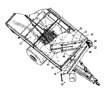
[0020] Fig. 1 is a perspective view of a grain cart with an upper auger
conveyor
section in the storage position.
[0021] Fig. 2 is a perspective view of the grain cart of Fig. 1 with the
upper auger
conveyor section in the unload position.
[0022] Fig. 3 is a fragmentary perspective view of the grain cart of Fig.
1 looking
down into a grain hopper with an auger feed gate in a closed position.
[0023] Fig. 4 is a detailed perspective view of the grain cart of Fig. 3
showing the
auger feed gate in an open position.
[0024] Fig. 5 is an expanded view of Detail 5 of Fig 1 showing the cylinder
control
valve, push-button switch, and indicator rod.
[0025] Fig. 6A is an expanded view of Detail 5 of Fig. 5 with the indicator
rod
indicating the auger feed gate is closed.
[0026] Fig. 6B is an expanded view of Detail 5 of Fig. 5 with the indicator
rod
indicating the auger feed gate is opened.
[0027] Fig. 7A is a schematic of a control system with the auger feed gate
being
in a closed position.
[0028] Fig. 7B is a schematic of the control system of Fig. 7A with the auger
feed
gate in an open position.
- 9 -
Date Recue/Date Received 2022-09-30
Detailed Description Of The Invention
[0029] Figs. 1 and 2 illustrate a grain wagon or cart 10 which has a general
construction similar to the grain cart disclosed in U.S. Patent No. 7,143,830.
he grain cart 10 includes a grain hopper 12 and a discharge conveyor 14. The
discharge conveyor 14 is shown in a storage position in Fig. 1 and in an
unload
position in Fig. 2. The discharge conveyor 14 includes an upper auger conveyor
section 16 with a tubular housing 18, which includes an upper auger 20. As
shown
in Figs. 1 and 3, the discharge conveyor 14 also includes a lower auger
conveyor
section 22 with a tubular housing 24, which includes a lower auger 26.
[0030] The upper auger conveyor section 16 is pivotally attached to the lower
auger conveyor section 22 via a hinge assembly 32. A movement actuator, such
as
a fluid or hydraulic cylinder 34 is operatively connected to the upper auger
conveyor
section 16 and is adapted to move the upper auger conveyor section 16 between
a
first position corresponding to the storage position of the discharge conveyor
14 (Fig.
1) and a second position corresponding to the unload position of the discharge
conveyor 14 (Fig. 2). It will be understood that the upper auger conveyor
section 16
may be rotated further than the storage position shown in FIG. 1 such that the
discharge end of the upper auger conveyor section 16 is closer to the ground
(in
further storage or transport positions). The hydraulic cylinder 34 is
controlled by a
control, e.g., lever, switch, knob, etc. (not shown), located on the grain
cart 10 or on
a tractor (not shown) which may be connected to the grain cart 10 to pull it.
It will be
understood that other types of known movement actuators (electric, mechanical,
and
otherwise) may be used for the movement actuator in other embodiments
consistent
with the scope of this invention.
-10-
Date Recue/Date Received 2023-07-19
[0031] Fig. 3 illustrates the interior of the grain hopper 12 and the
lower auger
conveyor section 22, which extends into the interior of the grain hopper 12.
The
lower auger conveyor section 22 includes a slideably movable auger feed gate
40
operatively connected to a fluid or hydraulic cylinder 42 which is adapted to
move the
auger feed gate 40 between a closed position (Fig. 3) and an open position
(Fig. 4).
In the open position, grain can flow into the bottom end of lower auger 26 for
transport through the discharge conveyor 14. An indicator rod 44 is affixed to
the top
of the auger feed gate 40. The indicator rod 44 runs parallel to the lower
tubular
housing 24 and terminates at a tip end 45 outside the grain hopper 12 near the
hinge
assembly 32. In this embodiment, the indicator rod 44 moves in one-to-one
correspondence with the auger feed gate 40. That is, for every inch the auger
feed
gate 40 moves, the indicator rod 44 also moves an inch. The hydraulic cylinder
42
may be controlled by a control, e.g., lever, switch, knob, etc. (not shown),
located on
the grain cart 10 or on a tractor (not shown) which may be connected to the
grain
cart 10 to pull it.
[0032] In accordance with one aspect of the invention, the grain cart 10
includes
a control system 50 generally shown in Figs. 5-7B. In general, the control
system 50
prevents the upper auger conveyor section 16 from moving towards the storage
position when the auger feed gate 40 is in an open position. In other words,
the
control system 50 provides a "lock-out feature" for upper auger conveyor
section 16.
For example, if the upper auger conveyor section 16 is in the unload position
(Fig. 2)
and the auger feed gate 40 is in an open position (Fig. 4), the control system
50 will
prevent the upper auger conveyor section 16 from pivoting away from the lower
auger conveyor section 22 and moving towards the storage position (Fig. 1).
The
control system 50, however, permits the upper auger conveyor section 16 to
move
- 11 -
Date Recue/Date Received 2022-09-30
from the storage position towards the unload position regardless of the
position
(open or closed) of the auger feed gate 40. The components and operation of
the
control system 50 will be described in more details in reference to Figs. 5-
7B.
[0033] The control system 50 includes a cylinder control valve 52 which is
affixed
to the hydraulic cylinder 34 as shown in Fig. 5. The cylinder control valve 52
includes a solenoid 54 electrically coupled to an auger feed gate position
sensor 56.
In the embodiment shown in the Figs. 5-7B, the auger feed gate position sensor
56
is a normally-closed push-button switch. As will be explained in more detail
below,
when the auger feed gate 40 is in the closed position, the normally-closed
push-
button switch 56 is open, Le., engaged, such that the solenoid 54 is not
energized.
When the auger feed gate 40 is in an open position (any position but closed),
the
normally-closed push-button switch 56 is closed, Le., disengaged, such that
the
solenoid 54 is energized. It should be appreciated that other types of auger
feed
position sensors may be used to monitor the position of the auger feed gate
40. For
example, a Hall effect proximity sensor may be used in alternative embodiments
in
conjunction with one or more magnetic indicator elements carried on the
indicator
rod 44 to monitor the position of the auger feed gate 40. In short, the auger
feed
gate position sensor 56 is not limited to the example structure shown in the
illustrated embodiment, so long as the auger feed gate position sensor 56
provides
accurate indications and actuations when the auger feed gate 40 opens from a
closed position.
[0034] The indicator rod 44 of the illustrated embodiment includes an element
such as a switch trigger 58, a spring 60, and a clamp 62 affixed to the
indicator rod
44. The switch trigger 58, which may be made of plastic such as HMW
polyethylene,
is slideably mounted on the indicator rod 44 and, therefore, does not move
with the
- 12 -
Date Recue/Date Received 2022-09-30
indicator rod 44 as the indicator rod 44 moves with the auger feed gate 40 as
the
latter moves between open and closed positions. When the auger feed gate 40
moves from an open position and approaches the closed position, the indicator
rod
44 and the clamp 62 affixed to the indicator rod 44 move downward and the
clamp
62 begins to engage and compress the spring 60 as the auger feed gate 40
continues to move. When the auger feed gate 40 reaches the closed position
(Fig.
3), the compressed spring 60 forces the switch trigger 58 onto and into
engagement
with a push button 64 (Fig. 6B) of the switch trigger 58, causing the normally-
closed
push-button switch 56 to become open, which de-energizes the solenoid 54. This
configuration, where the auger feed gate 40 is closed, the normally-closed
push-
button switch 56 is open, and the solenoid 54 is de-energized is shown
schematically
in Fig. 7A.
[0035] When the auger feed gate 40 moves from the closed position to an open
position, the indicator rod 44 and the clamp 62 move upward and the clamp 62
begins to move away from the switch trigger 58, which will begin to decompress
the
compressed spring 60. As the compression force on the spring 60 decreases, the
bias force of the push button 64 eventually pushes the switch trigger 58 away
and
the normally-closed push-button switch 56 returns to its normally-closed
position,
which energizes the solenoid 54. This configuration, where the auger feed gate
40 is
open, the normally-closed push-button switch 56 is closed, and the solenoid 54
is
energized is shown schematically in Fig. 7B. When the normally-closed push-
button
switch 56 is closed, i.e., the auger feed gate 40 is in an open position, a
visual
indicator 66, such as an LED light, illuminates to signify that the upper
auger
conveyor section 16 cannot be moved towards the storage position. This visual
indicator 66 is preferably located on the front of the grain cart 10 as shown
in Fig. 5
- 13 -
Date Recue/Date Received 2022-09-30
so that the tractor operator can see that the "lock-out feature" is engaged.
This
visual indication is advantageously in addition to another visual indication
provided
by the position of the tip end 45 of the indicator rod 44 relative to the
hinge assembly
32 joint between the upper and lower auger conveyor sections 16, 22. For
example,
the tip end 45 may be painted or otherwise made of a bright, contrasting color
to the
color of the grain cart 10, to thereby make it easier for an operator to see
the
indicator rod 44 and thus know the corresponding open or closed position of
the
auger feed gate 40. By having multiple visual indicators on the grain cart 10,
operators are more likely to avoid mistakes in operation as described in the
Background section of this disclosure.
[0036] With further reference to Figs. 7A and 7B, the solenoid 54 has two
operative positions. In the first position, a two-way channel/passageway 70 is
operative. In the second position, a check valve 72 is operative. As shown in
Figs.
7A and 7B, the solenoid 54 is electrically coupled to the normally-closed push-
button
switch 56 and the tractor electrical power 74 when a tractor (not shown) is
operatively coupled to the grain cart 10. When the solenoid 54 is energized,
i.e., the
normally-closed push-button switch 56 is closed, the check valve 72 is
operative. In
contrast, when the solenoid 54 is de-energized, i.e., the normally-closed push-
button
switch 56 is open, the two-way channel 70 is operative. The visual indicator
66 is
also powered by the tractor electrical power 74 based on the position of the
normally-closed push-button switch 56.
[0031 The cylinder control valve 52 is connected to one of the tractor
hydraulic
ports 80 via line 82 when a tractor (not shown) is operatively coupled to the
grain
cart 10. Line 82 is connected to pump side of the solenoid 54. The cylinder
control
valve 52 is also connected to a base end 84 of the hydraulic cylinder 34 via
line 86.
- 14 -
Date Recue/Date Received 2022-09-30
To this end, line 86 is connected to the cylinder side of the solenoid 54.
Inside the
cylinder control valve 52 of this embodiment, line 86 includes an orifice 88
and a
pilot-operated check valve 90. A piston end 92 of the hydraulic cylinder 34 is
connected to another of the tractor hydraulic ports 80 via line 94. The
cylinder
control valve 52 is also connected to the piston end 92 via pilot line 96
which is also
connected to the pilot-operated check valve 90.
[0038] The typical situation where the "lock-out feature" will be advantageous
is
when the grain cart 10 is being unloaded into a hopper trailer or truck parked
alongside the edge of a field. While unloading the grain cart 10, the auger
feed gate
40 will be in an open position (Fig. 4) and the indicator rod 44 will be
raised up
allowing the switch trigger 58 to disengage the push button 64 of the normally-
closed
push-button switch 56. In addition, the upper auger conveyor section 16 will
be in
the unload position and thereby aligned with lower auger conveyor section 22
and
both the upper auger 20 and lower auger 26 will be rotating to move the grain
from
the grain hopper 12 and through the discharge conveyor 14. With the normally-
closed push-button switch 56 disengaged, i.e.., closed, the solenoid 54 is
energized
and the check valve 72 is in the operative position (Fig. 7B) to prevent flow
from the
base end of the hydraulic cylinder 34 to one of the hydraulic ports 80.
Consequently,
the "lock out function" is enabled. In this "lock-out" condition, the tractor
operator
cannot command the upper auger conveyor section 16 to move from the unload
position to the storage position because flow of hydraulic fluid out of the
base end of
the hydraulic cylinder 34 is blocked by the check valve 72, such flow being
necessary to enable movement of the hydraulic cylinder 34 between positions
moving towards the storage position. Advantageously, this configuration
prevents
the tractor operator from inadvertently moving the upper auger conveyor
section 16
- 15 -
Date Recue/Date Received 2022-09-30
from the unload position to the storage position while the discharge conveyor
14
contains grain as it unloads the grain from the grain cart 10. This lock out
function
prevents grain spillage at the hinge assembly 32 between the upper and lower
auger
conveyor sections 16,22 and avoids having the upper auger conveyor section 16
moved towards a folded or storage position while full of grain (the heavier
weight
when filled with grain may cause damage to the movement actuator, for
example). If
the tractor operator closes the auger feed gate 40, then the switch trigger 58
will
engage the push button 64 which will open the normally-closed push-button
switch
56, thereby de-energizing the solenoid 54 such that the two-way channel is in
the
operative position. Consequently, the "lock-out feature" is disabled and the
upper
auger conveyor section 16 may be moved from the unloading position to the
storage
position.
[0039] The "lock-out feature" does not prevent the upper auger conveyor
section
16 from moving from the storage position to the unload position even when the
auger
feed gate 40 is in an open position, the solenoid 54 is energized, and the
check
valve 72 is in the operative position. To this end, if grain can flow past the
auger
feed gate 40 and into the discharge conveyor 14 (or even if not), the control
system
50 of this invention does not block movement of the upper auger conveyor
section
16 towards the unload position, as the problem of spilling grain moving
through the
discharge conveyor 14 is not exacerbated by allowing movement towards the
unload
position. Thus, the control system 50 of the embodiments described herein
provides
a selective lock out of only one type of movement of the discharge conveyor 14
to
help avoid some of the most problematic accidents and errors that may occur
when
operating the grain cart 10.
- 16 -
Date Recue/Date Received 2022-09-30
[0040] In another aspect of the present invention, the auger formed by the
upper
and lower augers 20, 26 is operatively coupled to the push-button switch 56 to
provide additional functionality. To this end, the actuator (not shown) for
the auger
receives signal from the push-button switch 56 to evaluate whether the auger
feed
gate 40 is in the open position or the closed position. Only if the push-
button switch
56 indicates that the auger feed gate 40 is in the closed position will the
auger be
able to start rotating to move grain through the discharge conveyor 14. This
arrangement avoids having the auger begin rotating when under a full load of
grain
entering from the grain hopper 12 past the auger feed gate 40, which could
damage
the auger or its actuator. Likewise, as set forth above, the lock out function
prevents
folding of the upper auger conveyor section 16 until after the auger feed gate
40 is
closed, which assures that the auger will continue to rotate to empty the
discharge
conveyor 14 of grain before the auger is stopped. These features in
combination
advantageously avoid having the auger start rotation under full load in this
embodiment of the grain cart 10.
[0041] The grain cart 10 and control system 50 of this invention therefore
provide
several technical advantages over the known designs. For example, the operator
is
prevented from inadvertently moving the upper auger conveyor section 16 from
the
unload position towards the storage position when the auger feed gate 40 is
open.
Consequently, the upper auger conveyor section 16 may not separate from the
lower
auger conveyor section 22, which would otherwise cause grain to spill out of
the
lower auger conveyor section 22 at the hinge assembly 32. Instead, the
operator is
forced to close the auger feed gate 40 before moving the upper auger conveyor
section 16 from the unload position towards the storage position.
Advantageously, in
the time it takes to close the auger feed gate 40, the auger can finish
clearing out
- 17 -
Date Recue/Date Received 2022-09-30
any remaining grain in the discharge conveyor 14. Cleaning out the discharge
conveyor 14 makes the upper auger conveyor section 16 lighter and protects it
from
being damaged when it moves from the unload position towards the storage
position.
[0042] The disclosed system and method for controlling the operation of the
discharge conveyor 14 offers benefits over other systems that rely upon more
complex ways to lock out the discharge conveyor 14 from folding. For example,
some systems monitor the speed of the rotating auger to enable a lock out
condition.
Other systems monitor the weight of the auger housing to enable a lock out
condition. Still other systems monitor both the speed of the rotating auger
and the
weight of the auger housing to enable a lock out condition. The disclosed
system
and method are much less complex, less costly to implement, and more reliable
in
operation than these other lock out systems. Furthermore, the system and
method
of the present invention provides more feedback to the operator of the grain
cart than
these prior designs regarding the auger feed gate, which cannot be seen from
outside the grain cart.
[0043] While the invention has been illustrated by a description of
various
embodiments, and while these embodiments have been described in considerable
detail, it is not the intention of the Applicant to restrict or in any way
limit the scope of
the appended claims to such detail. Additional advantages and modifications
will
readily appear to those skilled in the art. The invention in its broader
aspects is
therefore not limited to the specific details, representative apparatus and
method,
and illustrative examples shown and described. Accordingly, departures may be
made from such details without departing from the spirit or scope of the
Applicant's
general inventive concept.
- 18 -
Date Recue/Date Received 2022-09-30