Note: Descriptions are shown in the official language in which they were submitted.
CA 03064526 2019-11-20
WO 2018/217236 PCT/US2018/000116
=
EMERGENCY FIRE ESCAPE DEVICES OF THE OFF SHORE RIGS WITH
EMPHASIS ON A DETACHABLE ISLAND RIG
NAME OF THE INVENTOR : DR. PATURU SUMATHI ( THE SOLE AND FIRST
INVENTOR)
TITLE OF THE INVENTION : EMERGENCY FIRE-ESCAPE DEVICES OF THE OFF-SHORE
RIGS WITH EMPHASIS ON A DETACHABLE ISLAND RIG
CROSS-REFERENCE TO RELATED : US APPLICATIONS:
APPLICATIONS - 'EMERGENCY SALVAGE OF A CRUMBLED OCEANIC OIL
WELL'
US 9175549 ( JUNE 6, 2011)
- 'EMERGENCY DETACHABLE ISLAND RIG AND FIRE ESCAPE'
US 9884669 (NOVEMBER 3, 2015)
- 'FIRE-ESCAPE DEVICES OF THE OFF-SHORE RIGS WITH
EMPHASIS ON A DETACHABLE ISLAND MG'
( 15 /731, 327 )( MAY 25, 2017 )
: PCT APPLICATION:
- EMERGENCY DETACHABLE ISLAND RIG AND FIRE ESCAPE'
PCT/ US 16 / 000090 ( NOVEMBER 3, 2016)
STATEMENT REGARDING FEDERALLY SPONSORED RESEARCH: NOT FEDERALLY SPONSORED.
THERE WAS / IS NO JOINT RESEARCH AGREEMENT OF ANY TYPE.
This is a PCT application that claims the priority dates of the earlier
domestic and PCT applications as
mentioned above, which are herein incorporated by reference.
BACKGROUND OF THE INVENTION
There are innumerable petroleum oil wells bored into the oceanic floor by
highly evolved modern
technological devices to tap the petroleum reservoirs. Many oil wells are
clustered in the Gulf of Mexico,
Arabian sea, and in such oceanic-grounds, often about significant distance
from the coast line, such wells
bored through the ocean floor as far deep as 1/8 th of a mile from the surface
waters, to fmd their way into
the underground oil containments, spread many miles in area. Oil is collected
from the wells into surface
tanks in moderate containers, or into receptacles as large as ships.
1
CA 03064526 2019-11-20
WO 2018/217236 PCT/US2018/000116
The drilling and production of petroleum oil from the earth's mantle about the
ocean floor is shrouded in
great hazard to the natural environment that includes both marine life forms
and the terrestrial ecosystem
adjacent. The greatest hazard is the ignition of the entrained highly
inflammable gases like Methane,
causing dangerous fires, coupled with the risk of oil spewing and polluting
the ocean waters. Such two
man-made calamities at the same time can be uncontrollable with available
resources, and utterly
devastating to the healthy existence of the earth's planetary life forms. For
these reasons, error-proof
safety systems in under-water well digging, and highly trained personnel are
required by law in all
countries engaged in significant oil production. Despite that, catastrophic
events s are still occurring, as
the derived remedial measures through each adverse event experience are still
nascent and less than
perfect. Recent event in the Gulf Shores of Mexico ( involving BP Oil Company
Deep Water Horizon
oil well), wherein the ignition of the entrained Methane gas and its fire that
continued for 36 hours,
culminated in collapse of the surface structure of the well, resulting in an
ever increasing gusher from the
source. Several attempts to contain the spewing geyser from finding its way
into the body of water, and
into the Gulf Shores had failed, due to the inherently limited robotic
attempts, involved in a moderately
deep aquatic habitat.
As any unforeseen adversity can happen at any time before the completion of
the well to its last functional
detail, safety measures to weather off such events at any step of the
construction have to be in place, before
beginning to venture such operation. This CIP application enumerates
'Emergency Fire-escape Devices of the
Off-shore Rigs with Emphasis on a Detachable Island Rig' ( US application 15 /
731 327, May 2017). The
'Detachable Island Rig' ( DIR ) is one among the diverse measures described in
the parent application, said
measures however working in synchrony, to weather off any unforeseen event
throughout the well
construction and well operation. For the information of the said devices
otherwise operable, the original
patented application ( titled as 'Emergency Salvage of a Crumbled Oceanic Oil
Well', US 9175549 and the
PCT application PCT / US 16 / 000125 ) may be consulted. The original
application is also a parent application
for yet another PCT application titled as `Subsea.Level Gas Separator of Oil
Well Effluent with Incorporated
Emergency Measures on a Well Blow Out' ( also filed on this date) ( that
enumerate the devised prototype
models for dissipating a giant gas entrainment consequent to a well blow out.
The subject is contextually
relevant, also preventive in scope of otherwise catastrophic and devastating
consequences of a rig-fire.
Many inadvertent and unforeseen consequences were / are inherent to such
ventures as the deep sea
explorations, shrouded in dangers and always counting on the tides of nature
yet to be conquered by the
2
CA 03064526 2019-11-20
WO 2018/217236 PCT/US2018/000116
technological sophistication. Accordingly, the Author Inventor is neither
legally liable nor personally
responsible for any 'adverse events' difficult to differentiate either as a
mere association or as a consequence
responsible for any 'adverse events' difficult to differentiate either as a
mere association or as a consequence
of the application of the structural and procedural information herein
enumerated. Structural or procedural
application of this disclosure in different situations, innumerable and
unique, is a personal choice. Furthe-
more, analyzing and adapting swiftly to diverse and unforeseen situations
still remain as the professional
discretion and the deemed responsibility of the involved company and its
technological associates
participating in the day to day practice in the implementation of this
invention, in part or as a whole.
Based on the cost of a rig, and the life of the personnel involved, even a
major part of a permanent rig may
be constructed as a detachable island from the conductor platform, the latter
a possible inciting venue of a
rig-fire. In all herein enumerated prototype fire-escape models, utmost
importance is given to vital needs
thus far elusive, feared for the lack thereof, and yet herein accomplished
with ease and affirmation.
=
BRIEF DESCRIPTION OF THE INVENTION
The invention, delineates substantial accounts of fire-escape models of the
off-shore rigs with emphasis on
a 'Detachable Island Rig' ( DIR ) locked on a permanent 'under-water
basement', to be instantly detached upon
a rig fire, saving personnel as well as the property. A devised 'water-seal'
about its basement's fire-escape'
entry, not to be destroyed upon a rig fire, serves as an exceptional In-situ'
fire-escape model within
the confines of a rig. A fire-escape model is also devised as an 'off-site'
modular, to be improvised with
all types of rigs, including the DER. with a functionally intact basement fire-
escape, said modular being a safe-
guarded vital source of unlimited air-supply upon a rig-fire. An in-site'
under-water fire-escape modular is
also herein devised, for the most prevalent jack- up rigs, with no basement,
nor a provision for its elective
structuring. In all models, a 'spray-room' with needed accessories within and
outside, is devised to
circumvent all known adversities. Utmost importance is given to long-felt
vital needs like safe evacuation,
food, and fresh air-supply, the latter about an unlimited time - these
accomplished as affirmed provisions.
Not limited to the foregoing, the disclosure enumerates contextually
significant lift-boats and lifi-boats,
both with train-wagon wheels, lowered by remote control into the ocean waters
under fire-safe provisions,
the boats further safe-guarded against collision injury. The disclosure
further enumerates fire-safe spray-
walks, or spray-tracks with track-drives, or else simpler means of spray-
drives - each structured to be suitably
operable about any catastrophic events, settings, and their consequences, to
safely lead to the destination of the
3
CA 03064526 2019-11-20
WO 2018/217236 PCT/US2018/000116
'fire-escape' entry about a 'spray-room', he latter devised for all types of
off-shore rigs.
DRAWINGS
Figure-I: 'A Plan of an Emergency Detachable Island Rig', a schematic diagram
of a workable outline.
Figure-2: 'An Anchoring Model of a Detachable Island Rig onto a Permanent Base
Structure', a
schematic diagram.
Figure-3: 'A Water-Sealed Basement Entry Devised as an Emergency Fire-Escape
in a Detachable
Island Rig' - a schematic model.
Figure-4: 'A Water-Sealed Basement Entry Devised for Storage Purposes in a
Detachable Island
Rig' - a schematic model.
Figure-5: 'A Water-Sealed Basement Access Devised for General Purpose Entry
about a Detachable
Island Rig' - a schematic model.
Figure-6 'An Off-site Fire-Escape Modular' - a schematic model.
Figure-7: 'A Water-Sealed Entry Structure of an In-Site Fire-Escape within a
Jack-up Rig' - a
schematic model.
Figure-8: 'An hi-Site Under-Water Fire-Escape Modular Attached to a Jack-up
Rig' - a schematic
prototype model.
Figure-9: 'A See-saw Hammock Design of a Lift-boat in an off-shore Rig' - a
schematic, cut section
in part diagram.
DETAILED DESCRIPTION OF THE INVENTION
The herein disclosed inventions are directed to 'fire-escape' models of off-
shore rigs that envision an
emergency 'Detachable Island Rig' ( DIR ), the latter to be steered away from
the stationary rig by its
designated crew, upon an ignition fire, salvaging its working amenities. The
rig's permanent under-water
basement, by a devised 'water seal', not to be destroyed upon a rig fire, is
an instant 'fire-escape for the
rest of the crew, wherein its prototype yet serves as a 'schematic' for the
fire-escape models of other non-
detachable rigs including the conventional jack-up rig with no built-in
underwater basement.
=
It is a modem day irony that the fire is the greatest unsolved concern for the
off-shore rigs, amidst ocean
size of water. Probing into historical events is herein deservingly warranted
to delineate the problem, and
design a solution that must be 'as a whole inquiry'. The most recent calamity
in US territorial waters
4
CA 03064526 2019-11-20
WO 2018/217236 PCT/US2018/000116
involving BP oil well happened before the 'Production Tubing' and the
'Production Packer' were installed,
wherein the wide 'A' annulus acted as the tunnel for the gusher. The ocean
water in turn quickly found its
way into the oil containment through the expansive 'A' annular space of the
well. It was worse due to the
absence of the down hole safety valve ( DHSV ) placed in the 'Production
Tubing' ( the valve being the
last resort thereof, to contain the leak from a disrupted well ) as far below
the surface as deemed safe, to be
unaffected by a wipe out of the surface well head platform. In such instances
as an =installed 'production
tubing', yet, the well head should have a provision, to let any forced
emanations ( a gas entrainment, or an
admixture with a greater proportion of gases ) to pass through a 'Subsea Level
Gas Separator of Oil Well
Effluent' unit ( the Inventor's yet another new invention, mentioned earlier)
about the well head, that
dissipates the immensely pressured giant gas bubble, at the source. If that
fails to contain wholly, and part
of the gas bubble reaches the rig exploding into a rig-fire, the giant bubble
being reduced to a meager size,
the fire will not last incessantly feeding upon itself, as was the event about
the gulf shores. The DIR must
be steered away by the 'steering crew' from the source of continued danger.
All the unfailing measures
herein put together should minimize the fire, as also the rest of the crew
swiftly gets into the fire-escape
refuge of the rig. In a desolate oceanic habitat with limited off-shore
provisions, simpler the methods are,
lesser are the unforeseen and 'difficult to circumvent' situations - a
pervasive notion that herein resonates
at every twist and turn, be it an abstract thought or a statutory subject
matter, either deemed to impress.
In the prevailing oceanic climate of the oil wells, after a bore well
structure is disrupted, the ocean water
continuously gets into the oil well, whereas the oil rises to the surface,
because of the relative densities of
each, that could be contributing to the spewing gush at a later time, while it
would be a mere spill to start
with. As the ocean water forcefully fills the underground oil containment, its
pressure rises more and more
in a short time, forcing the lesser dense oil to rise into the ocean like an
eruption. Accordingly, it is
imperative that immediate action be taken to stop the ocean water pouring into
the oil containment
dampening its rising pressure, so breaking a brewing cycle. It is thereby
obvious that the preservation of
a functional rig is important for the needed emergency measures to plug the
well leakage at the earliest
possible instance when the leak is merely a spill, the same a formidable job,
later on.
Ground stability can be a factor in opting for a permanent base. In the model
herein described, the
Detachable Island Rig is an immovable structure with ground stability, yet
with provision thereof to steer
away from the base and the adjacent conduction platform ( a site of the
initial fire). Additionally, in
view of the crew, the ultimate destruction in Deep Water Horizon Oil Well
explosion is terrifying and
demoralizing. Whatever can be salvaged, should be salvaged, including all the
personnel in one pack,
CA 03064526 2019-11-20
WO 2018/217236 PCT/US2018/000116
accomplished, and how the structural arrangement should be geared towards that
goal.
=
It should not be a concern that the open working platforms of the DIR 108 may
be drenched by giant waves. As
in a ship, such open platforms are sufficiently high from the ocean surface,
and they get wet only as much as a
ship gets wet. The platform can be made as high as desired, but such height
also dictating the distance away from
the basement's fire-escape, to be traversed during an emergency, which however
can be amicably planned, as is
outlined later. The rig about its edges, may have weather resistant plastic
shielding with metal support rods in
equidistance. The shielding can have zippered window openings, for a fresh
breeze. They are of minimal
investments, but offer the highly desired work area cleanliness and comfort.
The base platform 124 of the rig is so structured that it is at a sufficiently
low level from the water surface, to
remain underwater even upon rising tides, and the island rig 108 is steered
down onto it, to be immovably locked
in a desired position. To that effect, suitable mechanical forces have to be
in place to overcome the built-in
buoyant forces of the DIR, and bring it down by few inches. A device of double
pulleys 126 shown in Figure-2,
positioned equidistance about the side walls within the basement 130, are
devised to maneuver a set of sliding
metal / steel ropes 128, their upper ends hooked to the ringed structures 129
on the sides of the DIR 108.
Additional rings, at times better operable, are positioned at higher levels.
Traction on the steel ropes 128 by all
pulleys 126 simultaneously will bring down the DIR 108. The grooves of the
pulleys are covered ( not shown
in figure-2 ) so that the ropes never get de-grooved. All the ringed
structures 129 also have circled non-
metallic ropes affixed, as at times they work better in maneuvering the DIR
onto the base platform 124.
The model of pulleys described needs a suitable structuring that fits for an
underwater basement. Each metal
rope 128 after it emerges from a small opened roof door of the basement ( said
doors are multiple in number
and situated in equidistance), passes through a tubular ( 'the rope tubular'
133 ) that is erected about the roof
door, the upper end of the tubular 133 rising to surpass the water surface
164. Said tubular structures 133 are
erected when the steered DIR returns to the base. Each tubular 133 locks and
articulates with a complimentary
structure around the roof door, in a car-trunk like water-tight closure.
Beneath the roof doors, there are roof
compartments 137, where the upper part of a metal rope 128 is normally saved.
A container-box ( not shown in
Figure-2 ) in the roof compartment unwinds the rope 128, when it is pulled.
Following the articulation of all the
tubular structures 133, the water within is suctioned and the roof doors
opened by a common key, to bring out
the terminals of the ropes 128. Each roof compartment has a switch to operate
a motor 134 of the basement, to
exert traction on the rope 128, the motors also controlled by a common device.
After the DIR is brought down
and locked, the ropes are disengaged to be saved in the roof compartments 137,
and the 'rope tubulars'
6
CA 03064526 2019-11-20
WO 2018/217236 PCT/US2018/000116
disarticulated. The traction of the motor 134 is by cog-wheel motion that
exerts a slow traction on the rope
128, so that the DIR may not dash onto the basement structures, or drift away
from the platform 124. The roof
compartments have solar-powered lights, to aid any activity after a night
fall.
The 'rope tubular' 133 is sufficient in its dimensions that a man can stand
within it on the permanent base 124.
A ladder structured like an inverted V is used to get into the 'rope tubular'
133. There is structuring also on the
base 124 to steady the ladder. The land mark roof windows are numbered, and
are signaled by solar- lights
covered by strong metal grid over glass, both in flush with the base floor,
and are put on as soon as the DIR is
detached. It is an option that the numbered 'rope tubulars' and their
complimentary structuring on the
permanent base are made with one inch difference between each, so that the
largest tubular can stalk the rest,
to be kept in the 'security' station 120 of the DIR in a space-saving manner,
to serve during an emergency.
On the base platform 124, the complimentary 'articulating structures' with the
rope tubulars 133 are secured
by watertight lids that are in flush with the base. The locking articulations
are thereby protected from
particulate matter settling and preventing a 'watertight locking'. The
multiple covering lids are also locked,
each opened by a similar key that also opens the multiple roof compartments
137.
The DIR needs additional forces to overcome its buoyancy, for the downward
traction to be effective. The
geometrical center of the DER. has a large room size metal block in its floor
structure that is in fact an 'air
capsule' that has an outer shell of water compartment that is kept frozen at
room temperature. The air capsule
imparts great buoyant effect to the DIR, in addition to the bottom metal
covered wooden platform doing so,
the air capsule dipping to the bottom of the platform. The metal block has a
nozzle that is capped and locked
normally. The water around the air capsule is kept frozen all the time. This
part of the DIR is structured like
a 'spray-room' ( to be described later) spraying cold water, the sprinklers
automatically activated upon a
fire-alarm. When the DIR is ready to be pulled down, the nozzle is unlocked
while water is let in, wherein
the downward traction by the ropes 128 are most effective. After the hectic
pace calms down, the water is
completely suctioned out of the metal block, as air is let in. It is now
readied to be capped again, while the DIR
regains its full buoyant effect. The air capsule has sufficient air volume to
counter the preconfigured weight that
the DIR may not exceed ( that includes the numbered crew), however, with a
wide safety margin. If the crew
had entered the basement, but for any reason, if it is confirmed that the DIR
cannot be mobilized from the base,
and fire is quickly spreading generating heat ( that can explode the air
capsule), the security crew and the
steering crew have to open the nozzle of the metal block by remote control, to
let out the air from the air
capsule. Each one of them carry the control at all times, so that at least one
would be able to do it. It has to be
7
CA 03064526 2019-11-20
WO 2018/217236 PCT/US2018/000116
done also, after the boats are mobilized, and the crew is ready to get out, if
fire is uncontrollable in a
mobilized DIR, so that the exploded parts of the DIR will not hit any boat
nearby.
In right positioning, the DIR 108 can be locked ( or unlocked) by equipment
similar to the locking of a car
door ( in a magnified size with an allowance for some imprecision ) by a
remote control. These multiple locks
are located on both sides about the floor of the DIR. Locking / unlocking is
done individually, each side being
also controlled by an universal button. With the press of a third button
following the rise of the DIR to the water
surface, the steering station 122 is activated to a smooth automatic straight
course, until taken over by the crew.
However, the engine is set in a fixed minimal speed so that the sudden
movement of the DIR is not jolting to
the rig structures. The DIR has retractable wheels ( wheels with 3600
mobility), for finer adjustment ( all four
wheels to work in synchrony, and independently controlled) of the DIR's
positioning. Other mechanical
anchoring devices can also be used together or in place of the car-door like
locking device.
At the junction of the corridor 110 and the DIR, a 'crash cart' is equipped to
disconnect the tubing 107, and the
wiring 105 that connect the two areas. Each tubing and wiring is differently
color coded, and every crew member
should know how to instantly disconnect or severe, and clamp or seal each
tubing and wiring. At the junction of
the corridor and the DIR, the threaded metal tubes 107 are made of conjoining
rubber tubing in a C or U
configuration 109 for their easy severing. The ends of the metal tubing 107
are clamped in any conventional
manner, before cutting the rubber tubing. Threading helps conjoining later by
instant 'joint structures' ( to be
described later). The wiring 105 is cut and sealed / insulated on either side.
Working with remote devices as
much as possible should be the priority, to minimize the wiring within the
DIR.
The signal to unlock the DIR from its base 124 is set by the key personnel
carrying the remote control.
Multiple sheets of burlap stored in reserve at strategic places in a roof
structure and above heavy equipment
of a DM / off-shore rig, to be instantly made wet and thrown on burning
objects / equipment / affected crew
members, are the most effective accessory measures in putting off the fire.
They are best effectuated in
conjunction with instantly closing the threaded tubular systems, to shut off
the unceasing inflammable gas
emission. Additionally, the heavy / costly equipment are wholly jacketed with
layers of fire-proof structures
and sheaths of burlaps over a water-proof underlay while manufacturing, their
tubing connections devised to
be threaded throughout, to reconnect when the tubing or the appended
structures are destroyed.
If the DIR 108 had caught fire, the sprinlders must control fire easily as the
DIR is now moving away from the
source of danger. The crew can move away only as far as it is deemed safe, but
working about the security
8
CA 03064526 2019-11-20
WO 2018/217236 PCT/US2018/000116
devices through remote controls, being also vigilant about the expert fire-
fighters left in the base, trying to
prevent the well explosion. The crew returns soon after the fire is put off,
and start the reparative processes.
Clearing of the rubble into the ocean is easier than a ground clearing. Once
emergency reparative processes to
restore the temporary and permanent well integrity are accomplished by
plurality of measures as described in
the original application ( US patent 9175549), a planned rig structuring is
done restoring its full function.
Amenities needed at the time of well maintenance is not as demanding as at the
time of well-digging.
When it is clear that staying back only endangers the lives of the fire-
fighters, everybody leaves the base.
It is in the best interest that everyone is trained in basic fire-fighting.
Those skilled and stayed back, should
jump into the ocean in threatening situations. They must dive in if they
caught fire ( to avoid surface oil) to
swim to clearer waters, that is, towards the darkest direction. The DIR crew
should keep vigilance with night-
vision binoculars, and as they leave, at least two will go in a lift-boat to
follow, by swimming if needed, and
rescue the fire-fighters. The solar lights of the boat hint the fire-fighters
the direction to pursue in the water.
When the DIR 108 returns to the permanent base 124, though not all locking
devices are operative, even few
in opposite corners are effective for stable DIR stationing. The divers should
clean the base components of
the locking devices, if the locking is unsatisfactory. Other commercial
locking devices can also be used.
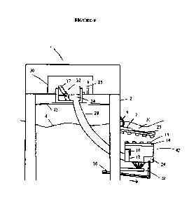
THE MODEL OF DIR BASEMENT FIRE-ESCAPE ( SITMATHI PATURU IN-SITU MODEL)
The DIR basement apart from a storage room and a 'power-house' for the
electric generators, it also serves
as a 'fire-escape' right within the rig. It can be a matter of concern of how
to access the underwater
basement from its surface DIR, without an unwanted compromise of this vital
structure. It is structured therefor,
with meticulous security measures, and unfailing accessories to safely reach
its destination. The model is named
as `Sumathi Paturu in-situ model', after its Inventor. The schematic of the
access model, not drawn to scale, is
shown in Figure-3. Being configured as a fire-escape, the basement's 'fire-
escape' access is structured to the
purpose, so that a quick entry is accomplished during a rig fire. The
following description, in conformity
thereof with the illustrating Figure-3, enumerates such devised model.
The DIR's basement fire-access is guarded by two room-like enclosures within a
specially structured 'spray-
room', the latter eminently protected from fire. Said two enclosures are : (1)
an 'inner' enclosure, structured as
a modular 'detachable' DIR's Staircase-Sliding Room ( DSR ) 154, above and
around the 'basement roof
window' ( BRW ) 179 of the basement 130 ( the same also conforming to be the
'floor window' of the base
platform 124), to rise up through the DIR's floor opening 100, to be
surpassing the surface 164 of the ocean
9
CA 03064526 2019-11-20
WO 2018/217236 PCT/US2018/000116
waters, the walls 103 of the DSR 154 locked in situ with complimentary
structures 160 on the permanent base
platform 124, in a model of water-tight 'car-trunk closure', their unlocking
operated by remote control;
(2) the 'outer' enclosure is a 'permanent' DIR enclosure ( PDE ) 168, erected
as a strong concrete floor
structure of the DIR 108, conforming to be a boundary of the DIR floor opening
100, around the DSR 154.
The DLR's Staircase-Sliding Room ( DSR ) - the 'inner' modular enclosure of
the basement entry, the DSR
154 is structured to be attachable, and to be secure, it is comprised of two
similar walls 103 on all four sides,
with independent locking articulations with the permanent base 124. As DSR is
the structure that safe-guards
the basement 130, it should be immune to flooding, breaking, or caving in.
Accordingly, the walls 103,
preferably in rectangular configuration, are made of very sturdy steel with
strong magnified locking devices
160 in equidistance about the base, effectuating car-trunk like 'water proof'
closing approximations. The
locking and unlocking of the 160 are operated by mechanical as well as
universal 'remote control'. The
DSR being not directly exposed to the exterior, and only touched by few ocean
tides, its footage is
protected from undue perturbations of the ocean waters. The male components of
the locking of the walls
103 are configured on the base platform so that particulate matter will not
collect when the DIR is steered
away. The DSR 154 is open about the top, whereas its floor is formed by the
roof window door 193 of the
'Basement Sliding Room ( BSR) 112, when it is locked. The walls 103 can
additionally have cement or
concrete reinforcement to give needed thickness, with metal brackets about the
top and the bottom.
The Staircase-Sliding units of the DSR - there are sets of slide-staircase
units ( SSU ), 158 about the
lengthwise dimensions of the rectangular basement entry about the DSR 154 for
the crew to get down from the
DIR 108, a quicker evacuation modality. Either of the set 158 is configured as
a top staircase structure, and a
bottom sliding structure. The top structure is fixed to the inner wall 103
about its upper end, further reinforced
lower down by transverse bars 159 about the inner wall 103, that also extend
to function as the long support
handles. The bottom sliding structure of the unit 158 is fixed below to the
BSR floor 161, further reinforced
higher up, by transverse bars 157 affixed to the walls 198 of the BSR 112,
that also extend to function as the long
support handles of the bottom structure. The top structure of the set 158 has
its staircase facing the interior of the
DSR 154, whereas the bottom structure, located within the BSR 112 is
positioned in an opposite direction, its
sliding surface facing towards the walls 198 of the BSR 112. The crew members,
to get into the DSR 154, sit on
the wide-spaced top of the outside stair case 173 of the DIR 108, while their
feet reach the seat ( not shown in
the figure) of the top structure of the set 158, with also sturdy support
handles to the seating, from where they
can climb down to the bottom. They sit on the broad bottom step as their feet
come to rest on the seating
structure of the bottom sliding structure about its transverse bar handles
157. Standing on the seating structure,
CA 03064526 2019-11-20
WO 2018/217236 PCT/US2018/000116
they turn around to sit on it, and then to slide down to the BSR floor 161, to
come to a rest about its side
windows 199, wherein they are also positioned to immediately slide down the
adjacent sliding structure 181 to
reach the basement floor. Said seating structures are broad and continuous, so
that few can stand additionally,
while one is sitting and getting ready to slide down. The floor of the BSR is
well cushioned to prevent injury,
if anybody accidentally slips from the seating structures. A disposition
allowing some 'intervening space
creation' plan ( the ISP ) between the two components of the SSU set 158
facilitates the needed space for the
two sliding roof windows 193. The opposing disposition of the two structures
of the sets 158 avoids steepness
in their structuring, if the DSR is deep, due to heightened rig platform to
prevent its water drenching. Each
component of the unit 158 with its own hand rails can be configured next to
each other without too much of
intervening space. As the BSR 112 has sufficient height, those waiting can sit
about the space between the slides
158, so that the roof 193 /179 can be shut, for the DIR to be steered away.
All the crew members sign in about
the entry-data portals, and a security-guard controls the DSR / BSR, while
also communicating with the steering
crew. After a loud buzz with also an announcement of DIR detachment, the BSR
roof window door 193 is shut.
The Basement Sliding Room ( BSR ) - the rectangular tub like 'basement sliding
room' ( BSR ) 112,
sunken from the base platform 124, is in a position corresponding to, but
substantially smaller than the DIR floor
opening 100, and is wholly positioned within the elaborately reinforced
structure 127 of the roof of the basement
130. The four walls 198 of the BSR 112 are of dimensions proportional to the
DSR 154. The BSR 112 has a
floor structure 161, while its roof opening 179 is in conformity thereof, with
the basement platform 124. It has
car roof like closures 193, moving side-wards. Figure-3 shows an opened roof
window 179. The reinforced
roof structure 127 accommodates two similar sliding roof closures 193, for
extra security. The top closure is
made of bullet proof glass, and the lower made of steel. The top closure is
locked first emergently, and the
lower locked later, the remote controls for both the closures being set forth
separately. The Figure-3 shows
the BSR roof window 179 below the surface water 164 just as the basement, and
so will be 'water-sealed' if
locked, whether or not the DIR 108 is detached, and whether or not it is
salvageable while locked onto its base
platform. It is for the reason - if the surface structures including the DSR
articulating structures are destroyed,
the ocean waters will immediately flood the roof closure 193, thereupon water-
sealing it.
The Sliding Structures of the BSR - the rectangular BSR 112, about its floor
161, has side windows
199 in its lengthwise dimension, and they open onto a common platform of
seating structure for the down-
going slides 181 that the crew can instantly slide down through, to get into
the basement 130.
The Permanent DIR enclosure ( PDE ) - on the DIR floor, conforming to the
boundary of the area
11
CA 03064526 2019-11-20
WO 2018/217236 PCT/US2018/000116
100, there is a rectangular permanent DIR enclosure ( PDE) 168 that surrounds
the DSR 154, and in turn
covers it, with its watertight DIR closure ( DC ) 170 / 192. The DIR enclosure
168 being a permanent structure
just as the rest of the DIR, it is made to be sturdy. About one of its walls,
the PDE 168 firmly affixes the two
walls 103 of the DSR 154 in their lengthwise dimension on one side, by strong
metal holders 175, closely
spanned in equidistance. Such fixed' metal holders 175 are shown in a
'downward incline', on the left side of
the Figure-3, wherein the walls 103 are locked with the complimentary base
structure 160, the model and the
movement of thefixed holders 175 being similar to the hinge-joints of a car
trunk closure. When the walls 103
are unlocked by remote control from the basement components 160, the fixed
holders 175 automatically
assume an 'upward incline', even though minimally, when the upper ends of the
walls 103 approximate the
DC 170 / 192, and the lower ends withdrawn towards the floor of the DIR 108.
On the other wall, also about the lengthwise dimension, the hinged metal
holders 175 about the PDE 168
are longer, as shown on the right side of the Figure-3, but are similarly
positioned i.e. in a disposition that are
mirror images to the holders about the left side. However, the right side
holders 175 are not fixed, and they pass
through slit-like openings about the two walls 103 of the DSR 154 allowing a
complimentary movement of the
right side walls 103, when the fixed holders 175 about the lefi side walls are
moved to either a downward or an
upward incline. The slit-openings, the hinge joints, and the lengthier
dimensions of the right side holders 175
allow free movement of the DSR 154. However, when rested on the base in a
locked articulation, the holders
175 yet support the right side walls 103. The slit openings have a watertight
cover, attached below their upper
borders, configured like the top closure of a gift-box with four walls, and
positioned about the DRS interior.
The cover is kept open and is manually closed, though rarely i.e. when the
rubber sheath 195 and its metal
sheath covers are compromised with a threat of water getting in, during
unexpected rise of the ocean tides.
Obviously, the lid also covers the lengthier right side holders 175.
The walls 103 about their widthwise dimensions have no holder supports, but
are locked in watertight
articulations 160 about the base, and additionally have the supports of the
inward legs ( described below).
About the opposing surfaces of the DSR 154 and the PDE 168, below the level of
the metal holders 175,
there is a strong conjoining rubber sheath 195 ( of vulcanized rubber) of
multi-layer thickness, and running
all around the outer walls of the DSR 154, as a water-tight barrier that
isolates and guards from the rising tides
and turbulence of ocean waters when the DIR is on its permanent base 124, and
the roof structures of the PDE
192 / 170 and the BSR 179 / 193 are open. The rubber sheath 195 is very
redundant with a U shaped fold that
allows the varying inclines of the holders 175. On the ocean side, the rubber
sheath 195, for additional
12
CA 03064526 2019-11-20
WO 2018/217236
PCT/US2018/000116
protection, is further covered by two separate layers of malleable metal
sheaths ( not shown in the drawing),
the latter also configured with redundant U shaped bottom folds.
=
The tripod supports of the DSR - apart from a locking base, the DSR is
configured to have firm tripod
footage, preventing it from buckling. All the four inner walls 103 have
closely spanned sets of two inwardly
diverging legs ( not shown in the thawing), to give a broad tripod-like base
in equidistance. The two legs have
deep-set outer threading, and each leg is threaded into two forked `tubulars'
with complimentary inner threading,
the common stem of the fork making 25-300 angle, wherein some are affixed to
the inner wall 103 above the
level of the holders 175 and some below the level, the legs resting on the
small area of the base platform 124.
Each leg is maximally threaded into the fork lubulars' before the walls 103
are locked to the base. Following
their locking, the free floating legs of each set are threaded down to a
required length, so that the strong rubber
caps of their lower ends are firmly resting on the small area of the base
platform 124. The stems of the forks
above the level of the holders 175 can originate in between the holders to
make such positioning possible.
The light weight structures of the DSR - when the DIR 108 is in open water,
the sturdy walls of the PDE
168 carry the weight of DSR 154 by the metal holders 175. To make the DSR 154
light-weight, its inner walls
103 on their inner side, have horizontally coursing air capsules 162 near the
lower ends, so that they are made
buoyant. The hand rails of the top staircase structure of the SSU 158 are made
hollow, rendering them light
weight also ( however, they are not heated up in a rig fire, being situated
deep within the 'spray-room'). That is,
the inner wall of the DSR 154 and its appended structures are made of buoyant
metal imposing no strain to the
*PDE 168. When the DSR is about the permanent base 124, said air capsules
however impart no significant
buoyant effect, to make its footage weaker, the inner wall being not in
contact with ocean waters.
The staircase provision to the basement - few of the sliding units 181 have
staircase provisions within
the basement 130, structured next to them, their top platform being common.
That is, one can climb up the
basement staircase, and through the top common structure, can get into the BSR
112. Both the widthwise
dimensions of the DSR and BSR also have staircases ( with dividing hand rails)
called 'widthwise staircases'
( WSC ). The lower sliding structures of the SSU unit 158 within the BSR 112
being diverging, the bottom BSR
part of the WSC can extend into the center between the said sliding structures
of the SSU, without intetrupting
their flow. People coming down the WSC can sit in the space between the
sliding units, while waiting to get to
the basement. If the basement is chosen as the living area, the security uses
the fire-escape entry for rounding,
as the rest of the crew uses the general-purpose basement entry, except in bad
weather.
13
CA 03064526 2019-11-20
WO 2018/217236 PCT/US2018/000116
The intervening space creation plan ( ISP ) is applicable to the staircase
structuring also. The top 2 steps
about the BSR 112, are created as 'detachable pieces', rested on the platforms
that are the back parts of the
'fixed staircase' structures about the level of step 3. Normally, each
detachable piece is held at its sideward
terminals by two prongs of a lift-prong located on either side of the basement
entry. The common remote
control button for both the lift prongs is positioned in the remote controls
that closes the BSR roof window
closures 193, and the detachable staircase piece on either side lifted before
the BSR roof windows are shut.
The detachable stair case pieces are sunken into the platforms they are
resting on, for needed stability, which
however will not obstruct them to be lifted up by the prongs. The announcement
for the closure of the BSR
roof window 193 is inclusive for the lift of the staircase structures also,
for people to clear off.
Re-articulation of the DIR with the permanent base - when the DIR returns, its
positioning on the base
124 is fine-tuned. It is obvious that the DIR gets on to the base in a reverse-
gear that it is capable of, on water.
It is helped by the metal ropes 128 ( Figure-2 ) passed through the rope
tubulars 133, and hooked to their
corresponding ringed structure 129 ( or to their circular non-metal ropes)
about the side walls of the DIR, to
pull the DIR backwards onto the base platform 124. The 'cog-wheel' motion of
the basement motors aid a
controlled maneuvering. On the base there is also a pair of 'rope tubulars'
133, located on either side of the
fire-proof corridor 110 that will exert traction on the most distal rings 129,
approximating the DIR with the
corridor 110. The DIR can also enter the base from a side, wherein only the
opposite side pulleys exert traction
following which the corridor-pulleys approximate it to the corridor 110. These
movements on water can be
easily accomplished. Other conventional devices can also be used additionally.
Following its positioning, the
DIR is pulled down onto the base by the traction of all the pulleys 126, while
the air from the air capsule of
the DIR's metal bottom is evacuated, as water is let in. The DIR wheels are
completely drawn-in at this time.
However, initially only one corner of the DIR 108 is locked to the base
platform.
Even before the DIR is brought down from the water surface, the holders 175
are kept in optimal upward
incline by lifting and holding few of the fixed holders 175 by two metal
prongs, so that the lower ends of the
walls 103 are in flush with the bottom structure of the DIR 108, and the
articulating lower ends of the walls
103 are protected during DIR stationing. Large particulate matter is removed
from the base, followed by
suction cleaning, under a bright light source from DIR electrical generators.
The legs of the inner walls 103
should be threaded deeper into the `tubulars', to stay free-floating at this
time ( for a perceptible and firm
snapping DSR articulation with the base structure. Following it, an alignment
is done between the PDE 168
and the base platform 124. All the four corners of the PDE 168 have 'pole
tubulars' that are precisely in a
vertical axis with the 'pole tubulars' embedded in the basement platform. The
plugging of the latter are removed,
14
CA 03064526 2019-11-20
WO 2018/217236 PCT/US2018/000116
and 'alignment poles' are passed through all the four 'pole tubulars' above
and below, while the positioning of
the DIR 108 is adjusted to that effect, the DIR wheels partly drawn out to
touch the basement. A video manually
held aids visual prompting for the steering crew. Aligning opposing corners is
tried first. Following a full
alignment, a snapping DSR articulation is done, to be perceived by the crew.
The locking of the rest of the
DIR corners is the subsequent event. The water within the DSR is suctioned to
detect any leaks by thorough
inspection. The legs of all the four inner walls 103 are now threaded out to a
length that firmly rests them on
their terminal rubber caps about the base platform.
The Spray-room of the Dili - the basement entry is structured in a 'spray-
room' wherein there are spray-
poles 200, each carrying multiple feeder tubes rising from the bottom of the
DIR, and drawing water for the
sprinlders, from a deeper level about the ocean, the surface water being
occasionally oil laden ( this being
applicable to all the sprinlders within the rig). The spray-poles of metal
supported by tripod bottom, are
clustered about the PDE 168, and the spray is a wide caliber stream 165 that
jets water all around, only sparing
1-2 feet about the DE 168. The sprinlders are directed down into the room,
self -bathing the poles, while some
are within the roof structure, drenching its layers. The roof sprinklers are
activated when the fire seems to be
spreading. The roof is made of layering as - a top metal sheet, layers of
burlaps, layers of mattress like sponge,
and a bottom grid of roof-beams, the layers capable of stagnating water. Other
fire-retardant materials can be
added. There are heating coils in the roof to dry up its layers, after the
fire is controlled. Covering the basement
entry, there is a lamp-shade like metal umbrella, with peripheral water
channels that protects the basement entry
from water. There is an inch of water stagnation on the floor. The walls of
the room are protected outside by
having similar roof and floor extended. No matter how insignificant the
initial signs of fire seem, the crew
should get into the spray-room. The doors and the entry of the spray-room are
guarded by 4-5 oversized over-
lapping layers of thick burlaps with heavy bottoms, the outermost layer bound
by large bands of Velcro to the
adjacent walls, hindering fire, and passage of gas and smoke. Those entering
open the door as little as possible,
and closing both the Velcro clasps and the door after them. The sprinlders
about the doors are wide and
forceful. Outside the doors, there is a high shelf like screen structured in a
U configuration, with convexity
outwards, and having high-powered fans of exceeding size, their upward incline
forcefully blowing off
approaching gases. Methane, a commonly encountered gas is lighter than air.
Such fans can be set forth in
strategic places about the rig, including the open areas. With foregoing
devices, the fire spreading into the
spray-room through the roof, the walls, or through the door is unlikely. The
spray-room has lights fixed on the
walls, their circuiting derived from the flooring. The spray room is modified,
wherein (1) if work stations are
isolated, there can be multiple spray-rooms, with multiple basement entries,
(2) if the work stations are in
CA 03064526 2019-11-20
WO 2018/217236 PCT/US2018/000116
different levels, there are upper level 'spray-walks' and spray-room, the
latter located above the lower level
spray-room, with a conjoining sliding structure, the basement entry being
single.
The Spray-walks - it is desirable for the rig to have 'spray-walks', mirroring
the spray-room. They cover the
entire area about the rig leading the crew securely to the spray-room, the
strategically located entry doors to the
spray-walks providing access / exit to different venues of the rig, including
the decks of the boats. The spray-
room and the 'spray-walks' can be 'modular' units, 'tailored' to the existing
rigs, and structured to be minimally
space occupying, yet serving the needs. The walk-way has two walls, with
sprinlders jetting water in the
passage, as well as the area in between the two walls. The doors of the walls
are positioned to be not opposing,
and the crew must be familiar with the structuring about their work venue, and
the course therefrom. The
brightly lit floor-arrows, solar powered, point to the direction of the spray-
room. If a basement is elected as the
living area, even moderate size rigs can avail space for the spray-walks. The
spray-room and the spray-walks
are activated as soon as the fire alarm rings, and reaching the nearest spray-
walk is an easy maneuver the crew
can count on, as the spray-walk / spray-room is reliably protected. It is
worthwhile activating them, though the
fire is seemingly trivial, as there is no water-damage to work areas, the
sprays of the sprinklers intended to be
fairly confined to the designated areas. Following significant fire damage, on
most occasions, only outer walls
of the spray-walks need restructuring, the inner walls being 'water-sealed'.
The Spray-tracks and Track-drives - if spray-walks cannot be accommodated in a
rig, less space
occupying 'spray-tracks' in metal or concrete, tailored as 'modular' canals (
water-filled upon a fire alarm),
dipped below the surface level of the rig's floor, can be substituted. If
below the rig's floor level 'spray-tracks'
are not elected, they are raised above the floor in a configuration of rail
road-tracts. There are 'Track-drives'
or 'Track-wheelers' in similar number as the crew members. They are built as
box-like enclosures ( sized for a
person peddling a tricycle), to be riding from each work station, the first
'wheeler' in the 'merger' track-stand,
to be driven by the first boarder. Track-drives with a simple technology of
locomotion, have two closely set back
wheels like a child's tricycle, for better stability within the 'spray-
tracks', and an airtight side door snaps about
the front seat. The water within the tracks will not over-flow, and the side
walls of the wheeler dip into the water.
A large spray-pole located within the wheeler derives water from the 'spray-
tracks' below. A 'suction' device
about the back-seat of the wheeler drives water into the spray-pole from the
spray-tracks. The wheeler made of
fire-proof material is otherwise structured like the spray-room about the
doors and the roof ( the latter however,
thin layered). The peddled front wheel is devised as in a bicycle, for needed
swiftness. The wheeler is jacketed
by multiple burlap layers, and covered by a sheet of burlap, its heavy bottom
edges dipping into the track-waters.
16
CA 03064526 2019-11-20
WO 2018/217236 PCT/US2018/000116
The closely spaced top sprinklers about the exterior bathe themselves, and the
surface burlaps, whereas the
interior sprinklers can be optionally put on, and their caliber controlled.
The wheeler is lit by solar head lights, as
the lit track-arrows direct to the spray-room, each wheeler entering a stand
outside the spray-room. If few people
in a work area can together approach a spray-wheeler, it can be devised for 3-
4 people, though there has to be at
least one bigger vehicle in each work station to transport an injured, with a
narrow stretcher affixed to the seats.
The wheeler's side wheels drawn to the center, and the walls converging about
the bottom, make the tracks
narrow for people to walk over, availing the space. On either side, the tracks
can have narrow sieved floor that
drains the drippings. Upon a fire alarm, the suction pumps within the wheelers
are activated, drenching them, as
people approach. To extinguish the fire quickly, a fire-victim has to
immediately wear a floor length 'bottom
heavy' burlap attire ( with full head cover ) hung by two Velcro bands about
the door, under outer burlap sheet.
The spray-drives - any one of the above devised plans is more appropriate to
the newly constructed rigs. Older
rigs can be tightly packed, being not able to avail any space even for the
spray-tracks. In such instances, they
can yet have modified 'spray-drives' or 'spray-wheelers', with additional
technological provisions. These
wheelers have wide-set back wheels for better stability, and have more height,
so that two water compartments
are structured about the top, a smaller one supplying the exterior sprinlders
with enough water to drench the
burlaps including the outer sheet reaching to the floor, and the larger one
supplying the interior sprinklers. The
peddling front wheel has wider diameter, so that the peddles even about their
downward circling, are sufficiently
above the floor to accommodate a bottom basin like receptacle to receive the
down-pouring water. The metal
receptacle extends from the side walls to spread all through the bottom,
except for the openings about the wheels,
where a fire-resistant rubber sheath covered by burlaps extend from the basin
to the top wheel frames allowing
sufficient sideward turns of the wheels. A recirculation draws the water from
the bottom receptacle to get to the
top tank again. The air tight snapping entry door about the front seat is
located above the basin receptacle. There
is a provision to make the interior sprinklers wider and forceful, if a person
entering had caught fire, as also he
wears the burlap attire hung about the door. The wheeler's water compartments
are cleaned periodically just as
the water-supply tanks are cleaned.
Ocean side exit from the spray-room - people who could not enter the DSR 154
and stayed in the steered
away DIR's spray-room, still have sufficient protection. The other side of the
spray-room opens to the deck
where the boats are stationed, so that when a warning alarm rings, they can
mobilize the life-boats. The
spreading fire in the steered away DIR is not met as a dramatic befalling, but
rather be reasonably foreseen.
17
CA 03064526 2019-11-20
WO 2018/217236 PCT/US2018/000116
The basement is a better refuge if fire is initiated in the DIR as it is being
detached - it is better to
get into the basement if a fire was initiated in a DER, its course being
unpredictable. Even when there is no
perceptible means of salvaging DIR, it is a wise choice to steer away the unit
by designated members, so that
some distance away, they can stop the engine and get out in boats, so that the
wreckage tumbles into water. Such
measure saves damage to the permanent basement, wherein the rest of the crew
had already entered. It is a better
safety measure despite the fact that the basement is built to be break
resistant and made fire-proof by a 'water-
seal'. The intervening space between DIR and the permanent base is devised to
be more about the basement
entry, to create a better 'water-seal' that still protects, even if the DIR
could not be mobilized.
=
Aeration of the fire-escape, if the crew is held back long - a means
appropriate to herein devised
models, providing fresh air indefinitely, is described subsequently being a
vitally encompassing topic.
ADDITIONAL OPTIONS AND SECURITY MEASURES
The basement as the living quarters - if opted, the basement can be used as a
living quarters, and as the
cooking and dining area. It is feasible, as the 'general purpose entry to the
basement' can be used on a regular
basis, whereas the BSR, DSR, and the DE are always kept open for a security
night-guard and a day-guard
rounding the DIR, the basement, and the permanent base. The basement is
equipped with 2-3 emergency exit
doors, with their outer structures configured to articulate with a watertight
'staircase tubular' of an emergency
marine unit equipped by the oil company, to aid evacuating the fire victims
needing immediate treatment.
There is a gas alarm that also rings in the basement, so that its ignition
sources are immediately put off. In the
'fire triangle' of `fuel-oxygen-ignition source', the ignition source is
eliminated in the immediate upper level.
Methane, the most encountered gas being lighter than air, the danger to a
lower level basement is eliminated
from the 'fire- triangle'. The rig is a smoke-free area, as smoking can create
a spark coinciding with a gas
entrainment, which is a rare event. If smoking happens on a daily basis, such
coincidence is easier. Hydrogen
sulfide is heavier than air, but due to its rotten egg's smell, it can be
detected easily at the upper level, and the
basement locked immediately.
If the basement is made as living quarters, the 'fire-fighters' and the
'security crew' still sleep in the upper level.
With sleeping, dining, and most of the day's activities happening in the
basement, it is only 8-10 working hours
that the crew is away from such safe-refuge. With the devised basement's
'aeration measures' the most basic
need is taken care of, as food and other supplies in abundance are in the
place. In essence, people living in a
fire-escape unit are in no danger of fire, except when they are away from such
a safe refuge. The basement
18
CA 03064526 2019-11-20
WO 2018/217236
PCT/US2018/000116
can have bullet-proof glass windows, the vast oceanic aquarium being
recreational, helping an otherwise
sensory-deprivation. A bright lighting enhances the beauty of the oceanic
wonders.
All crew members should have training in underwater diving, basic life
support, and intravenous ( IV ) line
management for hydrating a burnt victims ( IV hydration is paramount in the
basic treatment of burns), basic
management of burns, smoke inhalation, drowning, poisonous gas inhalation,
shock, and oxygen therapy
management. Each crew member should have diving equipment in the basement, to
get out of the basement
through emergency exits. The basement contains large canisters of soda lime, a
mixture of sodium hydroxide
and slaked lime ( calcium oxide or calcium hydroxide), to absorb breathed out
carbon dioxide. A closed circuit
system of SCUBA apparatus with single oxygen cylinder is the simplest under
water breathing equipment
suitable for the occasion. The basement's side exits are opened in an
emergency, to exit in a 'diving mode', as
once a door is opened, water gets in instantly, and few have to wait before
getting out. As there is always a
guard rounding, the crew is sufficiently fore-warned to get ready for any
event.
THE BASEMENT ENTRY FOR STORAGE PURPOSES
The Figure-4 shows a minimally modified basement entry of DIR 108 for storage
purposes. In this model, the
room that mirrors the DSR, and called as staircase room ( SCR ) 203, has a
large footage area 156 of the base
platform on one side of the basement roof window ( BRW) 150, to rest a wide
ladder 205 or a staircase ( either
one locking air columns), and for 2-3 people to stand. Underneath the BRW,
there are 'standing structures' 174
in the basement 130, leading to a stair case 172. The walls of the SCR being
configured with hinge joints of their
holders 175, as they were for the fire-escape entry, they are similarly
detached after the BRW sliding doors 151
are closed. There is no reinforced basement roof structure as it needs no
basement sliding room. Its staircase
173 about the PDE 168 is wide, to carry hefty structures. The DE 170 is one
piece structure, operably similar
as the car trunk's hood-like watertight closure, to create a widely configured
entry. The different structuring is
particularly useful to carry fire-victims into the basement, awaiting EMS pick-
up, apart from carrying storage
goods. The storage entry can be structured next to the fire-escape entry about
the spray-room, the most
appropriate location for its intended purposes. Structures otherwise alike to
those in Figure-3 of the fire-
escape entry, are similarly numbered in the Figure-4, and are not repeated
herein.
A GENERAL PURPOSE ENTRY ( GPE ) TO THE BASEMENT
Wherein the basement is elected as living area, the underwater basement has
also a sturdy permanent entry.
Figure-5 illustrates such schematic model. The following description in
conformity thereof with the illustrating
19
CA 03064526 2019-11-20
WO 2018/217236 PCT/US2018/000116
Figure-5, enumerates such devised model. The sturdy permanent entry structure
on the basement platform 124
is entered through a 'Housing-Structure' ( HS ) 428 located about a basement
corner 429 ( nearby the steering
station 122, and opposite the side of the 'spray room' 197 of the DIR), and
rising far above the water surface
164. It is accessed through the Housing Structure's Top Entry Room ( TER) 430.
An entry / exit side-door
( ESD ) 431 of the TER 430 is reached through a lengthy staircase ( LSC ) 432
rising from the floor 434
( conforming to the basement platform 124) of an Exterior staircase room (
ESR) 472, and through a small
staircase ( SSC ) 435 outside, the latter adjoining a bridging structure ( BS
) 436 ( connected to the DIR
platform), its HS terminal rested on the small walkway ( SWW) 457, 15-20 feet
long. A floor window ( FW )
437 with a watertight sliding window door ( SWD) 438 about the floor 434 (
conforming to the basement
platform 124) of the ESR 472 opens to the basement interior 130. The SWD 438
is 'water-sealed' upon a rig
fire, if the top structure is burnt. The FW 437 opening to a basement
staircase ( BSC ) 439 connects to the
basement floor 452. The SWD 438 is opened by a remote key that everybody
carries, and is designed to close
in few seconds automatically like an elevator door. The same key also opens
the ESD 431 of the TER 430.
Outside the bounds of the FW 437, the ESR floor 434 also has a locking and
articulating provision 454 for
an 'entry tubular', the walls of the latter separately articulated together (
for an easy assembly) providing a
watertight approximation that rises above the water surface 164, to enter /
exit, if the surface structure of the
ESR 472 is destroyed upon a rig fire.
The bridging structure ( BS) to the GPE - the SWW 457 is built about the base
platform 124, on a sturdy
concrete structure 458, the latter rising above the water surface 164 and is
in the same horizontal plane as the
DIR's work platform. Figure-1 shows a bird's eye view orientation of the HS
428 about the steering side
comer of the basement platform 124. The BS 436 is in fact configured in a
'truck crane' ( TC ) model, the
'crane structuring' 436 conforming to the bridging, being mounted on a
drivable truck 470 at the rig side
terminal. However, the crane / bridge structure 436 is positioned horizontally
or only minimally inclined, to
be resting on the SWW 457, but not materially connected, such disconnection
required of, during the time of
the DIR's detachment. The drivable truck 470 is stationed on the DIR floor,
whereas its loading platform
( i.e. the bridge platform) is in level with the DIR's work platform. The
bridging structure 436 can be
completely covered, so that the crew can use it in any weather, as the
overlapping approximation 450, will
protect from rain or snow. Yet it is instantly detached, due to its corner
steering side positioning. The BS
436 is protected by burlaps and sprinklers, whereas there are upturned fans
about the site of the top structure
450. The bridging enclosure has doors so that when it is driven into the rig,
the crew can still walk through.
AN OFF-SITE FIRE-ESCAPE MODULAR VITAL FOR ALL TYPES OF RIGS INCLUDING
CA 03064526 2019-11-20
WO 2018/217236 PCT/US2018/000116
A DIR WITH AN INTACT BASEMENT ( SUMATHI PAT1URU OFF-SITE MODEL)
There are many rigs without a safe and reliable fire-escape plan, or the DIR's
basement might be damaged.
Additionally, the steering crew and the fire-fighters of the permanent base,
at times need a destination. There
should be a safe-guarded outside refuge in such adverse situations, as an off-
site 'fire-escape' modular'. As the
spray-room and the spray-walks are reliably protected and activated soon after
the smoke / fire alarm goes on,
reaching a nearest spray-walk is the easiest maneuver the crew can count on.
Even amidst a deadly fire, reaching
the spray-room is easier than resorting to ocean waters. Yet an off-site 'fire-
escape modular' is advocated for
some above stated reasons, as also for some other more important, that soon
will be known.
Pertaining to the events involving BP oil company's 'Deep Water Horizon' oil
well blow-out resulting in
collapse of the surface structure, though the live events about the scene are
hard to extract or imagine, it was a
fact that the oil reached the gulf-shores rather quickly. Hence, the modular
though easily accessible to the crew,
should be sufficiently distanced, not to be engulfed by the fire, as the oil
may collect more at the interrupting
rig-side edge of the modular. However, it is only a far-fetched occurrence, as
the fire-fighters will not let the
fire spread on the ocean surface towards the modular, though oil may collect
about its edge.
The Figure-6, a schematic not drawn to scale, illustrates an 'off-site' fire-
escape 'modular' housing, small or
moderate-sized. The following description, in conformity thereof with the
Figure-6, enumerates such model.
The weather resistant 'modular' housing has a base 59 with a flat board (
barge- like) configuration. It has
sloping borders with small poles and hand rails, to support people climbing
up, the flat base 59 facilitating
transfer of a victim from water, by a single person. The barge- base is
entirely covered by metal sheets all
through its exterior, a safe-guard against approaching fire upon oil-laden
ocean surface. About the outer walls
of the housing, there are built-in watertight compartments 56 storing rescue-
supplies, and foldable stretchers.
The modular has a basement like room structure ( BRS ) 50 and a towered top
structure ( TTS ), the exterior of
the BRS built with fire retardant metal sheets. The ITS has a towered roof
room ( TRR) 51. The BRS 50 has
a staircase structure 58 on one side, to access the broad siding-door ( SD )
53, set forth about the TRR 51. The
SD 53 are 5-6 feet high, and slide sideward into the walls of the TRR 51 by a
remote control, whereas hand
controls are locked from inside. There is a small terrace 62 around the TRR.
The BRS 50 has an exit with a
high-set threshold and watertight BRS exit doors ( BRED ) 54, protecting its
interior from giant ocean waves.
When ocean waters are calm, the crew can enter through it, whereas it is
usually kept locked, except to let in
injured victims. There are mini ramps on either side of the BRED. Jets of
water 64 emanate forcefully from
the edges of the modular flat base, thereby preventing collection of oil about
the edges.
21
CA 03064526 2019-11-20
WO 2018/217236 PCT/US2018/000116
The interior of the modular - the BRS has metal block flooring set forth above
the flat base, said metal
blocks locking air capsules, to give an added buoyant effect to the unit. The
modular has the origins of
aeration tubes 16 with in one or two of floor-tubs 60 in its BRS interior that
travel vertically down into the
ocean, to then travel in an incline to the destination of a fire-escape unit
about a rig, to also terminate into the
floor tub(s) 24 ( to be detailed), the aeration tubes being the source of
fresh air supply to the fire-escape unit,
upon a rig fire. The BRS 50 has helium sacs secured to its roof, ensuring
stability of a swaying unit upon
ocean turbulences. The TRR 51 inside has a wide hall, and on the side
corresponding to the staircase 58
outside, there is a stair case entry, leading down into the BRS 50. The
staircase is broad enough to carry
injured victims in stretchers. Both BRS and TRR have bullet proof windows 57,
with installed night-vision
video monitoring. The TRR 51 has a high-tower 52, housing a guide-light 65, as
described below.
The guide light - the TRR's high-tower 52 housing a top glass closure, has
rotating ( about 3600) high
beam flood-lights 65 of a largest size, facing the sky. They are put on by the
residing crew as soon as the
fire alarm rings, so that any strayed crew members will be directed to the
modular. In a day time, the lights
are pastel colored, as pink, lemon yellow, or lavender, that contrast against
the blue sky. Additional high
sounding bells can be an option. The glass closure is break-proof, and is
warmed by heating coils.
The anchoring of the modular - the modular, lit by solar powered lights at
night fall, is anchored to the
basement of the DIR, or to the submerged legs of jack-ups, below the surface
water, by units of metal strings,
each unit 6 having two strings. Each string is made of sturdy but narrow metal
rods or poles ( about 2-3 cm
diameter) 67. In each unit, the adjacent metal rods 67 of a string are
connected by a linkage ring 68, wherein
said rings of one string are connected to the centers of the rods 67 of an
adjacent string ( Figure-6 illustrates
them in a magnified schematic). The arrangement prevents the strings from side
ward bending or sinking, so as
to maintain their desired axial length, thereby the modular precluded from
floating closer to the rig. The devised
arrangement helps to distance the fire spreading on water, and the wind-blown
gas to be dissipated, before it can
breeze to the area of the modular. The units of coupled strings 6 are
multiple, with two of them spanning
through the ends of the modular and the rig. The length of the rods can be
configured very long that only few
of them are incorporated thereof. Strings of low voltage solar lights
accompany the metal strings.
Added provision for the stability of the modular - the modular is better
stabilized due to helium sacs
61 secured all through the top of the BRS 50. If ocean is exceptionally
turbulent the modular may sway, but
comes back to its positioning due to the helium sacs 61 resisting such
instability. All the structures with in
22
CA 03064526 2019-11-20
WO 2018/217236 PCT/US2018/000116
the modular are not furnished but built-in, with securely bound sleeping beds,
and immovable utilities of
the kitchen and dining utensils of metal. The barged base-structuring also
provides a better stability.
Heating and lighting of surface waters - heating coils accompany the metal
rods 67, to be operative in
harsh cold weathers. The modular best serves its purpose, as the crew can swim
to a known destination not far
away, its direction led by the anchoring units, and its path lit up. The
lighter inflammable gases may not access
the surface water, even adjacent to the rig, as they usually ascend or spread
sidewise, but not descend in an
open expanse of the atmospheric air, and swimming to the modular is safer than
it may be anticipated.
Safety and utility provisions - the crew signs in through 'entry-data
portals'. A key person keeps vigilance to
the events of the ocean waters, and far away about the rig, through night-
vision binoculars. At least two crew
members holding clerical jobs must stay in the modular on a regular basis.
Clean water is pumped in from the
greater depths of the ocean. The modular serves as a destination for life
boats / lift-boats that can be temporarily
chained to the modular. Two-day worth of food supplies for the whole crew is
stored in the modular, to use and
refill prior to their expiration dates. The rooms have bullet-proof glass
windows 57 on four sides, with installed
security cameras. Security-crew vigilant about the territorial waters, also
surveys the modular on a regular basis.
Rigs monitored by a drone can additionally monitor the modular also.
An alternate means of anchoring of the modular at a safe distance from the rig
- if it is felt that
anchoring a modular to the legs, or to the submerged base structure of a DIR
is an undue strain, it can be
structured on an independently erected leg from the ocean bed, at a desired
distance from the rig. The leg must
have a very broad base for needed stability, or else, having two legs can be
an option. Few attachments to the
rig are still in place, to heat up the electric coils. The unit's barge-like
base is still positioned about the ocean
surface without an 'air gap', so that a single person can board with a fire
victim. However, the BRS exit door
( BRED ) way for the fire victims has two watertight doors, one with a
threshold 1 foot high, and the other 2
feet high, with ramps on either side, the higher threshold used when the water
level rises. Such structuring
serves the dual purpose that the modular is protected from ocean waters, yet
provides easy access.
THE FIRE-ESCAPE MODEL FOR A CONVENTIONAL JACK-UP RIG ( SUMATHI PATURU
IN-SITE MODEL)
Figures 7 and 8, not drawn to scale, illustrate a jack up rig based 'fire-
escape' unit. The following description, in
conformity thereof with the Figures 7 and 8, enumerate such devised model.
Structure 30 represents a spray-
room in a jack up rig 1, supported by its legs 2. The 'water seal' about the
fire-escape entry of a jack up rig is
23
CA 03064526 2019-11-20
WO 2018/217236 PCT/US2018/000116
created by an incomplete shell of water-enclosure 47, said enclosure having
four-walled outer structure 37 and
four-walled inner structure 33, each having a bottom, but open at the top,
with water circulating between the
inner and the outer structures. As the inner walls 33 of the water enclosure
rise above the outer walls 37, water
overflows as a water fall 39 about the outer walls 37 into a small water tub
40 that surrounds the outer walls 37
on all four sides about the spray-room floor 41. The interior of the water-
enclosure 47 comprises a top sliding
room ( TSR ) 32, and a bottom water-seal room ( WSR) 34. The TSR 32 is set
forth in the spray- room 30,
whereas the bottom WSR 34 sunken below the spray-room and the rig level,
stands on a sturdy traversing
structure 43 that courses between one leg to another, and materially
structured similar as the legs. The two
rooms within the water-enclosure 47 are separated by a fire-retardant floor 48
of the TSR 32 which is in
conformity with the floor of the spray-room itself. The floor 48 of the TSR 32
has one or more floor windows
( as per its dimensions) 46 through which sliding unit(s) 17 course from the
top of the TSR 32 ( about its
lengthwise dimension), to reach the floor 44 of the WSR 34. Each sliding unit
17 is made of a top structure and
a bottom structure with a small gap between the two, to create an intervening
space, for a fire-retardant window
closure 5 that slides sideward, like a car-roof closure. The gap between the
sliding structures 17 is covered by a
rubber sheet 3 that lifts up when the window closure 5 moves towards the
center to close the floor window 46,
whereas the rubber sheet 3 moves down to close the gap of the sliding unit 17,
when the window 46 is open.
The spray-room has stair case(s) 45 about the fire-escape entry to reach the
sliding unit(s) 17. The staircase
structures 45 positioned in equidistance are not solid structures, but are
frame-works that overlie the water fall
39. The water in the tub 40 is continuously let out, preventing flooding about
the floor 41 of the spray-room 30.
The spray-room has spray-poles 25, their structure and function similar as
those in the DIR.
The floor 44 of the WSR 34, sunken below the rig level, not only has the
affixed lower terminals of the sliding
unit 3, but also accommodates an originating curvilinear 'slide tubular' 28,
coursing to a fire-rescue modular
42, the latter submerged below water surface 4, the tubular' 28 also steadied
by supports from the leg 2
underwater. In large rigs wherein spray-rooms 30 can be only scattered due to
lack of needed stretch of space
in any particular area, there can be more spray-rooms 30, and equal number of
rescue modular units 42,
anchored to different legs of the rig, distributing the imposed load. The wide
slide tubular 28 has partitioned
seating to accommodate 4-5 people at a time, to swiftly reach an entry room 10
of the modular unit 42, said
room having a watertight door 12. The entry room 10 and the modular unit 42
have break-proof glass windows
to monitor the events outside, and to be guided when to lock or open the door
12. The modular unit 42 has a
floor tub 24 to receive the terminals of the air-tubing 16 originating in the
floor tubs 60 of the off-site fire-
escape modular ( Figure-6 ), and supplying fresh air for an unlimited time.
The modular 42 has an air capsule
24
CA 03064526 2019-11-20
WO 2018/217236 PCT/US2018/000116
14 in its top, to attain buoyancy and not to impart undue strain on the legs
to which it is secured by strong
supports ( of any preferred configuration) originating from sturdy transverse
structures 20 of the leg. .
The modular can be used as food storage unit for the rig. There is an
emergency exit door to open upon an
unexpected compromise. There are SCUBA oxygen cylinders for each crew member.
The crew can also get
out through a rescue marine unit that is deployed to emergently hospitalize
the fire victims.
Entry of the crew and water-sealing of the fire-escape - upon a rig fire the
crew should enter the spray
room wherein a fire-proof safe contains 'remote controls' for the sliding
window door 5, to be picked up by
each. When a person is ready to slide down, he opens the window door 5 by the
remote control, to slide down
immediately through the sliding unit 17 into the WSR 34, as the window door 5
automatically closes after, in
few seconds. The sliding unit 17 and the slide tubular 28 have staircase
provisions on one side to transport fire
victims to safety, the medical rescue supplies stored in multiple locations
along the transit ( the stretchers have
wheels and are structured as a wedge about the leading end, to counter the
steep of the slide it can be rolled on,
by two people in a controlled manner). In case the gas-fueled fire is
uncontrolled, and had spread to the spray-
room, the top structure of the inner wall 33 that rises above the outer wall
37 is the structure that is consumed
first, whereby it will not contain the circulating water from within the water-
enclosure 47. The water
immediately flows into the TSR 32, water-sealing the sliding window door(s) 5
and the WSR 34. For an
unfailing water-seal when fire had spread to the spray-room, the top risen
part of the inner wall 33, on the far
side of the sliding structure 17, is made of a material that easily crumbles,
to let the water flow-in. The multiple
feeders 8 originating about the leg level underwater, ascend through the roof
of the slide-tubular 28 to reach the
water-enclosure 47 traversing all four sides, to make the water fall 39 even
and strong. The tubular 28 about the
'air-gap', and the sunken outer walls 37 of the water-enclosure 47 are
protected by layers of burlaps, and wide
surface sprinlders originating from the feeders 8.
The modular safe-guard - it is important that the modular unit 42 is
sufficiently protected. The obvious
danger is the heavy-weight structures of the rig losing their footage and
tumbling down, at least their tail
ends falling onto the modular 42, as an early or a late event upon a rig fire.
A modular surface-guard 31,
positioned in an incline, and secured to the two legs, is a protective
structure, covering the modular all through
its stretch about the legs, to be obstructing and diverting a falling
structure. It also has anchoring chains 9 to the
legs 2, said chains having redundant length. Spanning all through its length,
it has a surface air column 7 that is
devised to be maximally sized about the leg side, and moderately sized on the
opposite side. Additionally, it has
studded bottom magnets 23, wherein the magnetic poles facing the modular unit
42 are similar as the top
CA 03064526 2019-11-20
WO 2018/217236 PCT/US2018/000116
magnetic poles of the magnets 15 studded on the top of the modular 42. The
surface-guard 31 is devised to let
a falling structure tumble into the ocean, sliding down on its incline, and
diverted away from the modular 42.
Wherein the surface-guard had not resisted the weight, and had broken from the
leg, it still protects the modular
42 by several means: (1) it resists sinking by its buoyancy and its additional
anchoring chains 9, the latter
remaining intact, being redundantly tied and not taking the impact of the
heavy weight, about the time it had
fallen; (2) it maintains its devised incline due to wider air capsule 7 about
the leg side, making the weight
further drift into the water; (3) it will be repelled by the similar magnetic
poles of the modular so that the
weight as a whole will not impact the modular 42 with an exceeding force; (4)
its underwater disposition
makes all the contacting objects lighter than they actual are. If the world
wide experience had taught that the
bottom of the rig had not collapsed even in the event of a catastrophic fire,
the modular unit 42 can be
structured between the legs, right under the rig.
EMERGENCY BREATHING PROVISIONS FOR ALL FIRE-ESCAPE MODELS
With an off-site fire-escape modular as herein advocated, to be improvised
with all types of rigs, emergency fresh
air provisions in an unlimited manner to the fire-escape units, is
accomplished as a reality. It is done as follows.
Originating from a floor tub of an off-site fire-escape modular, a number of
large color coded air-tubes 16 of
metal travel vertically down about few feet into the ocean, where they
angulate to travel in a downward incline
towards a DIR basement, or to an in-site fire-escape modular of a jack-up rig,
to also enter underwater, through a
vertical metal tubing of their floor tubs. They carry fresh air from the off-
site modular, the latter never involved
in a rig-fire, reliably safe-guarding the air-tube terminals. The travelling
air-tubes 16, except in their vertical
terminals at both ends, are made of uninterrupted sturdy rubber tubing,
covered by lengthy segments of threaded
metal tubing, connected by intervening closely wound spring like metal coils,
such structuring giving resilience
to the travelling air-tubing. The ends of each segment of metal tubing have
air tight sealing with the underlying
rubber tubing, so that upon a structural compromise, only the threaded metal
tubing is replaced by joint
structures, whereas the breach of the rubber tubing within, may remain. As the
air-tubes 16 are originating and
terminating into large floor tubs ( 24, 60 of Figures 6 and 8), consequent to
their structural compromise, the
tubs fill with water, and alarms ring on both ends, alerting the crew. To find
the area of the tubular compromise,
the terminals of both sides that are normally kept open, are capped ( said
caps being 'injector caps', secured to
the terminals of the air-tubes), the water is completely suctioned out from
the floor tubs ( 24, 60), and while
the lids of the off-site terminals are kept closed, in the rig terminals, each
cap is opened to detect which air-tube
is leaking. There is water in all air-tubes, but only the leaking air-tube
keeps filling the floor tub with water.
The compromised air-tube(s) are further tested with air-injection with closed
lid(s) about the rig side of the
26
CA 03064526 2019-11-20
WO 2018/217236 PCT/US2018/000116
terminal(s), while the lids of the off-site terminals are still kept closed.
The divers inspect the entire length of the
involved color coded air-tube(s), for emerging air bubbles about the
compromised area. The injected air being
voluminous, the rising air bubbles are made to be easily detected, even if the
breach is minimal. Such testing is
performed in day light, with an artificial light-source, when ocean waters are
calm. The involved area is severed,
and replaced by a 'joint structure'. The water from all the air-tubes 16 is
suctioned out, for their proper
functioning. With multiple air-tubing provisions, a compromise during the time
of a rig-fire may not be feared.
There can be two sets of tubing 16, to terminate about the opposite sides of
the basement. Water is diverted from
the floor tubs ( 24, 60) before they get full, to prevent flooding. The
threaded vertical terminals being metal,
optionally the whole tubing can be replaced. The off-site modular being
guarded by its inmates, there is
vigilance to these vital structures.
FANNING COVERS
=
At times, it is the dramatic befall of catastrophic events that preclude any
protective measures coming to the
rescue. An explosion accompanied by fire, can be such an event, when rising up
of the lighter inflammable
gases on fire, will suddenly surround the large and tall structures of the
rig. The fire-protective jackets of these
structures instantly made wet, can be a saving measure to some extent.
Additionally, as 'gas chasing' measures,
all tall structures of the rig can have a steel grid of exoskeleton ( also
conforming to all structural locomotion)
wherein suitably sized fans ( that are instantly turned on, upon a fire / gas
alarm), are scattered in strategic
positions, to blow away the gases approaching from the direction of their
source. The fans drawing-in the air
from the opposite direction at the outset of the event, forces the lighter
inflammable gases to rise to the sky, and
not to spread sidewise. Said grid of frame additionally has powerful
sprinklers all through, drawing water from
a deeper level about the ocean, whereby the most vulnerable structures of the
rig are protected from the
approaching gas and fire. Tall structures like-rig cranes with telescoping
towers, however are not amenable for
such plan, though the arch curtain of fans as described below can be
protective. For the extreme complexity of
a rig, no single measure addresses all the adversities that are expected and
encountered. For that reason multiple
devices with either one of them fitting for any one of the diverse structures
and encounters are herein described.
FANNING CURTAINS
The rig can additionally have a curtain of high-powered fans in a tall arch of
metal grid ( to be structured as
tall as necessary) rising from the sea, and spanning from one side of the rig
to the other ( preferably over
the fire-proof corridor 110 of the DIR ), shielding the rig and its tall
structures from the side of the possible
danger. The high arch is supported by strong metal / concrete base structures
with top air capsules, situated far
27
CA 03064526 2019-11-20
WO 2018/217236 PCT/US2018/000116
beneath the water surface, restrained in place being affixed to the cross bars
about the legs. Said air-capsuled
structures should remain under water, as significant heat can blow up their
air capsules. The arch of frame also
supports powerful jets of sprinklers, not letting the gas-fire by-passing
them, towards the side of the rest of the
rig. The tall arch will not preclude the DIR from steering away, as its course
is towards the opposite direction,
and its tall structures are protected during the few minutes it is preparing
to be steered away. All the structures
herein mentioned can be appended to the existing structures of any type of
rig. However, it is best suited for
new rigs, as the disposition of the taller structures needs to be carefully
planned.
PROTECTION OF ROOFED / CLOSED ENCLOSURES
The enclosed structure within the rig can have outlets spread all through the
roof structure and rising many
feet as inverted J structures to let off the gases, but not letting in rain
water. They protect the people occupying
the room. The rig should have a circuit of air tubing traversing through the
bottom level of all the rooms, and
also extending to its open areas, said circuit of tubes drawing air from the
utmost bottom of the 'air gap' about
the safe side of the rig. It is made maximally forceful as the gas alarm goes
on, to be powerful gas-chaser from
roofed / closed enclosures, quickly filling the room with pressured air,
coming from the opposite direction. In
conjunction, the up-tilted fans located about the bottom level of the room,
can further aid the gases to ascend
quickly to the roof, or not enter the room at all, helping the fire to cease.
In the case of DIR, the lower
terminal of the air tube near the steering station, courses vertically
underwater, to then turn towards the
steering direction in an incline, to rise to the surface at a distance, the
terminal of the tube having locked air
capsules, to naturally stay floating. A J tube is appended to the terminal
that always stays in open air, despite
rising tides. It is part of the DIR, and needs no severing when it is steered
away, though most of it needs to be
detached when the DIR returns to station. For safety, all the devices are
monitored by a drone.
SPECIAL FEATURES OF THE RESCUE BOATS DEVISED FOR OFF-SHORE RIGS
The herein devised life-boats and or lift-boats are not accessories but
invariable aids in rigs without: a
basement with an in-situ fire-escape; an sin-site' fire-escape modular; a
spray-room with spray-walks; the
spray tracks with track-drives; or spray-drives - as there is no devised
protection about the rig vicinity.
The life-boats - most of the life-boats 138 are stationed in the DIR adjacent
to the spray-room 197
( Figure-1 ). A life-boat has special features needed of its intended purpose:
a fire resistant surface, bottom
wheels like those of a train-wagon, and two ladders on one side, the side also
having intervening black stripes
to be identified as the side to be approached, while the whole boat is painted
white, for enhanced visibility; the
28
CA 03064526 2019-11-20
WO 2018/217236 PCT/US2018/000116
boat's hemi-section on the opposite side of the ladders having thicker weight
wood preventing toppling of the
boat with the weight of a 'rescued' climbing up the ladder, or alternatively,
having Velcro bound centrally
situated helium-filled sacs in the boat-interior, to be secured to the side of
the ladders before boarding, the sacs
replaced back, thereafter; raised rubber-guards, strong but yielding, about
the exterior, preventing collision
injury; water tight compartment storing rescue-supplies ( analgesics like
Tylenol, hospital-gowns, dressings)
and secured-oars with a snapping joint to an anchoring metal chain, to
disconnect the boat from the rig; solar-
powered light source put on by remote control, upon a rig-fire happening after
a nightfall, and a built-in break
resistant lighted compass. A GPS connection is a future option, as the rigs,
not being far away from coast line,
should have a dedicated GPS line to direct the lost crew members in ocean
waters, to the rig and / or the
shore. At least a compass directs to the north or south, and thereby the east
or west, to reach the coast line,
and not be lost in the ocean-waters until the break of the dawn, hinting the
directional geography.
The boat-exit from a conventional jack-up rig - the conventional jack-up rigs
are set up higher
with an 'air-gap', and letting out the boats in an emergency is a challenging
proposition. There must be a
plan for their smooth and safe exit instantly, by mere click of a remote
control. It is implied that the boats
are built in the manner devised herein. If not, at least the wheels as herein
devised, appended to existing
boats should not be felt as a hardship, for the reason, moving a boat without,
is a hardship by any standard.
There are rail road-like tracks starting from the deck and reaching the ocean
surface, the tracks structured
in an air-tight 'ocean tubular' with fire-resistant surface, covered by 4-5
layers of burlaps. It has spray-poles
inside feeding water to the self-bathing surface sprinlders outside. The
'tubular' is supported by cross bars,
extended from a leg. The 'ocean tubular' and the cross bars impose no strain
upon the leg, as their bottom
extensions are further supported by air-capsuled metal-blocks underwater,
anchored to the legs by sturdy cross
bars. The rail-road like tracks within a down sloping tunnel-like interior of
a deck run parallel to its walls,
wherein the boats with train-wagon wheels, stall in a row. The tracks make a
smooth L turn as they exit the
deck. The ocean-tubular has hand-rails running on either side of the tracks so
that the boarders can hold lightly,
to feel steady, during the downward sojourn. Each boat is restrained by side
chains that the boarder disengages
after boarding, to mobilize it on the slope, with also a push if needed, while
he is firmly gripping the hand rails.
The boarder wears fire-proof attire stored in the deck. Large fans about the
tubular exit, face upwards to blow
off the lighter inflammable gases. The tubular exit is closed normally by car-
garage like air-tight sliding closure,
its lower indentations for the tracks also made air-tight. The deck is
modified into a spray-room, if there is no
space for its structuring within the rig, the latter also not having an in-
site fire-escape modular for similar
reason ( it is presumed all the rigs have a deck as a boat-stand, to which the
'ocean-tubular' can be appended),
29
CA 03064526 2019-11-20
WO 2018/217236 PCT/US2018/000116
and the 'track drives' or the 'spray drives' are driven to the 'deck, to
safely exit in boats. These rigs must
invest in an off-site fire-escape modular, as a destination for those so
evacuated. The boats' surfaces have
raised rubber guards to protect against collision. Similarly, the terminals of
the ocean tubular and the legs have
rubber-guards about the ocean surface. To return the boats to the deck, a
group works together, some leading
the boats to the 'ocean tubular', and others pulling them by chains on the
tracks. Each boat thereafter, as
before, is restrained in its destined position upon the tracks. If the boats
have regular wheels, their tracks have
to be carved in the floor, or a path defined by closely-set side rails, or
else, un-boarded, they are maneuvered
throughout their course ( yet initially chained in a row).
As an alternative thereof, all the boats can be stationed on the tracks, the
first boat stopped by a cross bar that
moves horizontally in and out of the track, to stop or let out a boat. By the
click of a remote control, it moves
out of the track to let out a boat, and moves in after its passage, to hinder
the boat behind, unless there is
another click, to let it out. A boat's sloping front and back with sufficient
gap between each boat, allow the
plan to work in the configured manner. Each boat is not restrained by chains,
and hence, is also released from
outside. As the deck is locked, and only the crew are the boarders from
inside, a button next to the cross bar
can be pushed, to let out the boat. In emergencies, the exit door is kept
unlocked for the crew to get out easily.
The water-proof remote controls to the exit-door and also the 'let-out' cross
bar, both put together, has to be
carried in the pocket of every crew member, in case a boat has to be let out
from outside.
A boat exit from a D1R - in a DIR, the boat enclosures 125 (Figure-1 ) facing
ocean side, have following
safe exit plan: the enclosures with down-sloping floors are triangularly
devised in a vertical plane, conforming
to a 105 angle on the rig side and a 300 angle on the ocean side, a down
sloping roof conforming to a diagonal
plane; the boats are restrained on the sloping floors by sloping roofs; the
sloping roofs conforming to down-
sloping ramps when completely slid into the water by a remote control; the
boats on wheels thereupon sliding
over the sloping floors and the sloping ramps, onto the ocean waters; the
ramps having sideward ramp tracks,
and strong but yielding rubber guards about the lower edge, to be 'shock-
absorbers' upon a boat's collision.
=
Returning to the rig, the boarder should secure the metal chain to connect to
the boat, and then enter the
enclosure, wherefrom he can pull the boat onto the ramp. He hooks the chain to
a wall to steady the boat,
and the ramp made to retreat about its sideward ramp-tracks, to its original
positioning, by the remote
control ( it is delayed until all the boats return, if it is a common roof for
multiple enclosures). The chains
are then loosely secured to the 'enclosure fasteners', to maintain their
length. If multiple boats are let out
when a DIR cannot be detached, even if not boarded, they are floating in water
connected by lengthy
CA 03064526 2019-11-20
WO 2018/217236 PCT/US2018/000116
'fasteners', and so can be returned to the enclosures. However, on most
occasions, the boats are let out from
a DIR after it is detached, but the fire is uncontrolled and the DIR found to
be unsalvageable.
In a different embodiment, the DIR boat enclosure approximates a rectangular
configuration in a vertical plane,
like a car garage with a sliding door, but having a sloping floor. There are
rail-road like tracks that extend into
the ocean waters, through indentations about the door, that is made air tight
as a whole. The tracks have
rubber-guards about their ocean terminals. The boarder temporarily chains the
boat until the door slides up
sufficiently, after which a boat is released, and the door locked. Standing
fans about the door blow off the
approaching gases. This model, as also the one preceding, lets the boats out
with or without a boarder.
If a DIR platform is too high, the model exactly similar as for the fore going
jack-up rig can be elected for
the DIR, to be used by a remote control, even by the exiting 'steering crew'
and those left back in the 'spray-
room'. For the limited extent of the 'ocean tubular', supporting cross bars
from the DIR are appropriate and
reliable. This model has an added advantage that a single exit can be easily
closed, when the DIR is stationed.
The lift-boats - in addition to the life-boats there are 'Lift-boats' in the
rig, devised for lifting the 'severely
injured' from the ocean waters. The lift-boat otherwise has the general
features of a life-boat. Though a victim
can be pulled easier under-water, lifting him is harder, as once the victim is
above the water surface, the weight
in air comes into force, and the rescuer has no solid-footage to bear even a
moderate weight. A person may tilt
a boat down to roll the 'rescued' into the boat, and then straighten the boat
to get in from the opposite side, in a
boat with sloping base, but with the configuration of a lift-boat, it is hard
to accomplish.
The Figure-9 illustrates the schematic model of a lift-boat 500, better
devised to be larger than a life-boat,
so that more than one person to be nursed, are accommodated. To provide room,
its bottom is made flat rather
than sloping, as also it ensures better stability and thereby an undivided
attention of the rescuer(s), if the ocean
waters are turbulent. A cut-section in part 518 of one side of the boat
interior depicts the flat based structural
arrangement. It has four wheels as those of a train wagon, and it has rubber-
guards scattered about the
contacting areas of its exterior. The boat has a lift-hammock ( LH ) 502 on
one side of its exterior. The LH is
made of a strong nylon net that also has a weather resistant canvas as a
lining, and is covered by soft padded
sheet ( not shown in Figure-9), tied to the hammock on four corners by Velcro
bindings. The soft padded
sheet has pillow cushions on the sides, to prevent head injury to the victim.
The cradle like LH 502 has strong
curved central support 514 and smaller side supports, all made of metal-framed
wood. The central support
514 is perpendicularly connected to a short central plank 508, and the side
supports to short side planks 512.
Said short central plank 508 is secured to the boat edge by a central hinge
510, whereas the short side planks
31
CA 03064526 2019-11-20
WO 2018/217236 PCT/US2018/000116
512 are secured by side hinges 520, all the hinges rotating about the axis of
a curved metal rod 534, coursing
about the boat edge, the structuring as a whole devised as a `see-saw'. The
rolled lower terminal of the LH is
of metal-framed wood, for it to stay afloat in water. The other side of the
boat has two hanging ladders. The
LH side is referred as hammock side ( HS ), and the ladder side referred as
ladder side ( LS).
On the hammock side ( HS ) of the boat interior there is also a receiving
hammock ( RH) 506 made of
nylon net not lined by a canvas, and supported by long side planks 504,
connected to the small side planks 512
of the LH 502, through the rotating sideward hinges 520 of the see-saw, about
the axis of the boat rod 534. The
center of the RH 506 is configured to have a long and sturdy central plank
516, connected to the small central
plank 508 of the LH 502 by the rotating hinge 510 of the see-saw, about the
boat rod 534. All the long
planks of the RH 506 are connected by a cross bar running about the edge of
the boat interior.
There are helium sacs secured by Velcro, about the midline of the boat
interior, positioned nearer to the
comers, to be accessible, unhindered by the RH 506. Few are attached also to
the side wall on the HS, under
the RH 506, to off-set the weight of the LH 502, that may otherwise down-tilt
the HS. All the long planks of
the RH 506, about the mid position, have removable heavy weight metal spheres
attached to their under
surface, to contribute weight and aid a rescuer trying to lift the LH 502.
Their mid-positioning prevents them
from hitting the bottom of the boat in a rough sojourn. Also about the middle
of the long planks, there are
'sponge-holders' 540 on their upper surfaces, to hold the victim on the RH.
The 'sponge-holders' 540 are
large sponge blocks secured by Velcro bindings that the rescuer can undo one
at a time, starting any side, so
that the 'rescued' is slid down to the bottom of the boat, in a controlled
manner.
During rescuing of a burnt victim, the rescuer after swimming to the HS of the
boat along with the victim,
positions the victim in the LH 502. Objects being lighter in water, it is
easily done, and the 'rescued' is
secured by restraint belts 532 that have larger than usual size adjustable
buckles for easy handling. The
Velcro bindings of the hammock cushions in the lower comers are untied at this
point. The LH 502 being
moderately sized, even two people can be belted at one time. Cross belting is
more secure. The rescuer must
change the helium sacs from the mid line of the boat, to fix them to the side
wall of the boat on the HS
unhindered by the RH, to offset the tilt of the boat, so that the victim(s)
may not be submerged, though the
wooden central and side supports, and the rolled up wooden terminal of the LH
502 also make the LH float,
their metal frames preventing these projectile structures from breaking,
during a rough sojourn.
After getting into the boat, the rescuer positions himself on the central
plank of the-RH to lowers it, so that
32
CA 03064526 2019-11-20
WO 2018/217236 PCT/US2018/000116
the LH 502 will be lifted up. The rescuer stays in a best position to be able
to receive the victim onto the RH
506, by pulling the LH soft padding, after disengaging the belts 532 and the
upper Velcro bindings at this time.
The network spaces of the RH 506 are without canvas to accommodate the legs of
the rescuer to sit or stand, if
either position is more convenient. After the victim is steadied against the
sponge-holders 540, the rescuer gets
off the RH 506, and slides down the victim by undoing the sponge-holders one
at a time, and will belt-buckle
the victim at two places to a bubbled air mattress about the bottom of the
boat. The planks of the RH are then
slid down to be securely fastened to the side of the boat. The interior of a
lift-boat is protected by weather
resistant canvas. A bubbled mattress is better protected following an isolated
puncture than a single-
compartment air mattress. A sponge mattress is an alternative.
Lift-boat with inflatable lift-mattress - in yet another embodiment the LH is
provided with an inflatable
mattress ( protected by over-sized expandable knotted mesh, and covered by a
padding about the top, both
allowing needed expansion) that is air inflated. After a victim is restrain-
belted ( said belting not hindering
expansion of the air mattress), the air mattress ( bound about four corners by
Velcro ) is air-inflated to rise
to the edge of the boat. The air mattress has narrow width, and is configured
like an air-bench ( that is lifted
in vertical height ) rather than an 'air-mattress' it is named as. It is tied
to the LH back so as to keep such
configuration of a bench. It has an egg-crater structure, with wider cavities
in the centers of the sides and
the bottom to minimi7e the air needed, yet serving the purpose. Air pumps and
other devices of metal are
preferred, or they are in-built in the boat, to minimize any shocks and
breaks. Solar-powered batteries are
best suited for use. In the setting of an air mattress, if see-saw device is
not chosen, a receiving hammock
inside the boat is still desirable to safe-handle an injured victim. However,
it is better to have the see-saw
device also, as it is a sure and swift modality, in case an air mattress is
accidentally punctured in the transit.
Multiple air pillows, IV ( intravenous ) transfusion fluids ( vital in burns
cases), hospital gowns, breathing
aids, analgesics like Tylenol, and dressing supplies are stored in a boat
compartment. The boat walls has
hooked rings structured as 'near circles' so that a hung infusion may not be
easily disengaged. All crew
members learn to do an IV line while trained in basic life support ( BLS )
training while they are trained in
basic fire-fighting, as it may be a long wait before the EMS takes over.
If basic life support with chest compressions are needed, the see-saw is an
instantaneous rescue, though the
air mattress is an easy device. Hence, it is wise to equip the boat with both
devices for a sure rescue. With
air mattress is an easy device. Hence, it is wise to equip the boat with both
devices for a sure rescue. With
33
CA 03064526 2019-11-20
WO 2018/217236 PCT/US2018/000116
Insurance coverage can be a factor in planning against a DIR. But it can be a
long wait before finding a
suitable rig during a precarious time. The insurance premium can be lower for
covering the construction to
restore the best functional state of the rig, tested by 'trial runs' rated as
the 'best' and not the 'near best'.
=
THE VULCANIZED RUBBER - all the rubber washers and assembly devices of rubber
incorporated
in the rig tubing, in the water tight sealing of the basement fire-escape
entry and such other, are made of
vulcanized rubber, the only type that can resist the degrading attack of the
petroleum analogs.
THE INSTANT JOINT CONFIGURATIONS AND CLOSING CAPS
The invention further envisions a model of tubing, and methods of instant
system joining or closing, for all
future units, or as a replacement-tubing for existing units. Said tubing is
structured to have a deep threaded
configuration on the inside or the outside, traversing the entire lengths.
Inner threading is better ( though
manufacturing is more involved), as outer threading can collect sediment and
lose its precision, and needs
cleaning with a firm bristled brush. The treading of the tubing, small or
lengthy, can involve the well and its
vicinity, the rig, the air tubing, the appended tubing structures of costly
equipment, facilitating instant joining
or closing of a compromised or broken system, aided by means of - (1) 'Instant
joint-structures' - devised
to be shaped as I, T, J, L, C, U, Y etc. with similar inner or outer threading
as the tubing itself, to be inserted
for system joining, when a conduit line is broken. The working of the `joint-
structures' conforms to a 'sliding
screw', aided by two or more 'conjoining' I shaped tubing with complimentary
threading on the opposite side.
The 'conjoining' I tubing have their threaded outer diameter smaller than the
threaded inner diameter of the
involved tubing system and devised 'joint configurations', or else, their
threaded inner diameter larger than
the threaded outer diameter of the rest. When a conjoining I tubing alone is
suffice, it is inserted all by itself,
as a sliding screw. The functionally uninvolved middle part of the 'joint-
structure' is enlarged externally for
handling, even by robotic maneuvers; (2) 'Closing caps' - they have
complimentary threading to their stems
( i.e. having a smaller dimension and outer threading, if the tubular system
has an inner threading, and the vice
versa), for closing a system, when system joining is of no option. The
functionally uninvolved external part
of the stem terminal enlarges to double the size or more, ending in a sturdy
and massive closing cap, to resist
enormous pressure at times exerted by the tubular system at the terminal, and
the massive cap with similarly
sized distal stem is amenable to robotic maneuvers. Simple closing caps with
complimentary threading are
used to temporarily seal one end of a severed tubing while the other severed
end is worked on.
How to find the source of gas / oil leak and mending it - about the oil-tubing
of the rig confines and
34
CA 03064526 2019-11-20
WO 2018/217236 PCT/US2018/000116
outside, oil / gas sensing 'equipment' are placed at equidistance, each
numbered, defining its territory. When
leak occurs following a tubular damage, its territorial equipment rings its
alarm first, though other alarms ring
later, as the leak spreads. The devised computer soft-ware notes the timing,
however, the one that first rang, is
the source ( unless the leaks are multiple). The leak is confirmed by the
adjacent alarms that rang immediately
following. The computer sets forth the chronology, for an instant information.
The security crew familiar with
all the numbered territories, should emergently deploy the instant joint
structures. The 'production tubing'
within the well has its own pneumatic plugging device, the 'Emergency Plugging
Oil Conduit' ( EPOC ),
disclosed in the original application ( US 9175549), deployed after a well
blow-out with oil leak ( to be
done when the oil-leak is a mere spill). As the 'joint structures' are fixed
in dimensions, the length of the
tubing to be severed should be properly configured. On the other hand, as the
minimal length of a damaged
tubing to be severed cannot be minimized any more, the number of the joint
structures ( with one or more
`conjoining' I tubes) are to be properly configured before severing the tube.
The I configurations are
structured as both `joint-structures' and `conjoining tubes the latter with
complimentary threading. The
leak is insulated first, and the tubing including the I tubes to be inserted,
are articulated outside, and then
the damaged tubing is cut, for the articulated set to be inserted. One cut end
is temporarily closed by a
simple cap, while the other is worked on. The final manipulations of the two
conjoining I tubing are done
in-situ, to establish a conduit line, with vulcanized rubber washers also for
a fluid-tight closures. A distorted
tubing may need an intervening U / C joint. A bent L-shaped curve needs an L-
joint, whereas a complex
interconnection needs a T- joint. The crew must have a mock practice of
possible maneuvers. The 'joint-
configurations' can conform to two designs - 'subtle' or 'striking' ( 'Sub' or
'Sin'). In the 'subtle'
configurations, the devised curves are less obvious.
Unceasing oil / gas emission from a source that cannot be detected / mended is
a cause of an unceasing fire,
or else for an uncontainable pollution of the eco-system. Hence, such
structural mandate is as important as
all the other security measures put together. Moreover, what needs to be
herein implemented is only a small
step forwards in means familiar, however, with a big leap thereof, in the
remedial functions achievable.
The time old wisdom says: 'The time and tide wait for no man !' ; Let the tide
in time save a man or
men, and then some more.