Note: Descriptions are shown in the official language in which they were submitted.
CA 03064606 2019-11-22
WO 2017/205935 PCT/AU2017/050538
- 1 -
CASING FOR CONNECTING POWER CORDS
Related Application
This application claims priority from Australian Patent Application No.
2016203688, the
contents of which are incorporated by reference.
Field
The present invention relates to a casing for connecting power cords.
Background
A number of connection devices have been used to connect a plug and socket of
two power
cords.
The cords may be held by internal grips that are passively biased against the
cords.
However, the cords generally pull through the grips under tension which causes
power
between the cords to be disconnected. The plug and socket remain inside the
device and
the device needs to be opened to confirm the disconnected state of the cords
and to then
reconnect the plug with the socket.
If a power tool is in use and suddenly stops working the tool may be left on
while the
device is opened and the cords are reconnected, which is particularly
hazardous as the tool
may suddenly become active again without warning when the cords are
reconnected.
Such connection devices generally provide a weather proof connection around
the leads
but are not water proof as there is no complete seal around the device.
The devices all have a main clasp that simply clips opposite sides of the
device together. If
the clasp is knocked or kicked, the device can open and allow the plug and
socket to be
accidentally released and/or allow water inside the device.
Due to the risk of water incursion, the connection devices are not suitable
for use on work
sites especially those subject to pools of water or rain.
PCT/AU2017/050538
CA 03064606 2019-11-22 Received
26/04/2018
H kag \ Interwoven \NRPortbl DCOCAG \ 16860969_1 docx-26/04/2018
- 2 -
Summary
In another aspect the present invention provides a casing for clamping onto a
power cord
including first and second shells with a hinge to connect respective first
sides of the shells
and a latch to mechanically connect the second side of the shells, the casing
including a
port to receive the cord and a grip mechanism to resist the cord being pulled
out of the
casing, wherein: a grip mechanism is provided in each shell, in opposing
relation, to grip
opposite sides of the cord and each grip mechanism includes: a grip member and
a biasing
element that exerts a bias force to urge the grip member away from a base of
the associated
shell; the grip members being mounted to rotate on respective axes in and out
of associated
compartments; wherein each grip member is able to deflect inwardly of the
compartment,
toward the base of the shell, against the bias force of the spring, when
subject to a lateral
closing force as the shells are closed together in order to accommodate the
cord; and
wherein the grip members rotate out of the respective compartment toward the
cord in
response to axially applied pull-out tension on the cord so as to clamp the
cord and thereby
resist the cord being pulled through the grip members.
In one aspect, the invention provides a casing for clamping onto a power cord
including
first and second shells with a hinge to connect respective first sides of the
shells and a latch
to mechanically connect the second side of the shells, the casing including a
port to receive
the cord and a grip mechanism to resist the cord being pulled out of the
casing, wherein: a
grip mechanism is provided in each shell, in opposing relation, to grip
opposite sides of the
cord and each grip mechanism includes: a grip member and a biasing element
that exerts a
bias force to urge the grip member away from the base and toward the cord;
wherein the
grip member is able to deflect toward the base of the shell, against the bias
force, when
subject to a lateral closing force as the shells are closed together in order
to accommodate
the cord; and wherein the grip members rotate toward the cord in response to
axially
applied pull-out tension on the cord so as to clamp the cord and thereby
resist the cord
being pulled through the grip members.
AMENDED SHEET
IPEA/AU
PCT/AU2017/050538
CA 03064606 2019-11-22 Received
26/04/2018
H kag \ Interwoven \ NRPortbl DCOCAMI 6860969_1 docx-26/04/2018
- 2A -
In one embodiment, the casing further includes an opening for receiving an
other cord and
a second set of grip mechanisms, arranged in opposed relation in the first and
second shells
to grip the other cord and resist pull-out after the cords are electrically
connected inside the
casing.
In one embodiment, the casing further includes seals between the first and
second shells
and a locking lever to pull the shells together and energise the seals,
wherein the lever is
mounted to the first shell and has an associated pivotal latch intermediate
ends of the
locking lever to hook onto a catch on the second shell, and an over-centre
pivot connection
connects the locking lever to the first shell so that inadvertent release of
the lever is
resisted when the lever is moved into an engaged condition to close the
casing.
In one embodiment, the locking lever is hinged to the shell between external
side ribs.
In one embodiment, a free end of the lever is tucked against a side of the
casing when in
the locked position to protect the lever from accidental release.
AMENDED SHEET
IPEA/AU
CA 03064606 2019-11-22
WO 2017/205935 PCT/AU2017/050538
- 3 -
In another aspect, the invention provides a casing for connecting first and
second power
cords, the casing having a set of grip mechanisms with facing grip members
that have
serrated surfaces arranged to dynamically grip one of the cords and provide
increased grip
pressure in response to tension applied to the cord in order to resist the
cord being pulled
through the grip members and out of the casing.
In one embodiment, the grip members are biased toward the cord.
In one embodiment, the casing further includes a second set of grip mechanisms
to engage
the other cord such that neither cord is able to be pulled out of the casing
while the casing
remains in a closed and locked condition.
In another aspect there is provided a power cord with a casing fixed on an end
of the cord,
the casing including: two shells hinged together on one side, to move between
an open and
closed condition; a lock to hold the shells together in the closed condition;
an opening in
one end of the casing in which a cable of the power cord is received; a port
formed in an
opposite end of the casing for a cable of a second power cord; and an internal
bay in which
a socket connector of the power cord is mounted, the bay also accommodating a
plug
connector of the second power cord when connected to the socket connector;
wherein the
casing further includes a grip mechanism mounted in each shell, each grip
mechanism
including a spring biased grip member, the grip members being biased against
the second
power cord as the casing is closed and locked, the grip members further being
pivotally
mounted to rotate toward each other in response to axially applied pull-out
tension on the
second power so as to apply increased grip pressure to clamp the second power
cord and
thereby resist the second power cord being pulled through the grip members.
In one embodiment, a seal is provided in the port formed of a half-cylindrical
seal in each
shell, the half-cylindrical seals having internal annular sealing fins to seal
against the
second power cord.
In one embodiment, each half-cylindrical seal in the port includes a plug
which pulls
through an aperture in the respective shell to locate and secure the seal in
the port.
CA 03064606 2019-11-22
WO 2017/205935 PCT/AU2017/050538
- 4 -
In one embodiment, another seal is provided in the opening, fitted around the
first power
cord, and a gasket is fitted into a groove in one of the shells, the gasket
extending around
the bay and under the respective seals, the gasket being formed of a
continuous loop of
expanded foam-molded material.
In one embodiment, the seals have lateral wings that taper to allow the gasket
to transition
laterally out from under the seals such that an upper surface of the wings is
substantially in
line and flush with the gasket.
In one embodiment, a blade that matches the shape and profile of the gasket
projects from
the other shell to energise the gasket and engage the seal around the first
power cord when
the shells are closed together.
In one embodiment, the socket connector of the first power cord has integrally
moulded
ears with holes for receipt of fasteners to secure the plug connector into the
casing.
In one embodiment, the lock has a latch coupled to one of the shells for
engaging a catch
on the other one of the shells, the latch being hinged to a pivoting locking
lever for
additional leverage and enhanced compression.
In one embodiment, the locking lever is hinged to the casing between external
side ribs.
In one embodiment, a free end of the lever is tucked against a side of the
casing when in
the locked position to protect the lever from accidental release.
In one embodiment, the socket connector of the first power cord has a light to
indicate the
first power cord is live.
In one embodiment, the shells are formed of transparent material to allow a
visual
inspection of the connection between the first and second power cords.
CA 03064606 2019-11-22
WO 2017/205935 PCT/AU2017/050538
- 5 -
Brief Description of the Drawings
The invention is described, by way of non-limiting example only, with
reference to the
drawings, in which:
Figure 1 is a perspective view of a casing with a first power cord;
Figure 2 is another perspective view of the casing;
Figure 3 is an underside perspective view illustrating a shell of the casing,
the power cord,
gasket and seals;
Figure 4a is a topside perspective view of the shell, power cord, gasket and
seals;
Figure 4b is a partial perspective view of detail 'Z' shown in Figure 4a;
Figure 4c is a partial perspective view of detail 'Y' shown in Figure 4a;
Figure 5 is a cross-sectional view of the casing with the first power cord
secured in the
casing;
Figure 6 is a cross-sectional view showing a second power cord secured in the
casing and
connected to the first power cord;
Figure 7a is a side view of the casing in a closed condition;
Figure 7b is a cross-sectional view of the casing, along the line B-B show in
Figure 7a;
Figure 8 is a perspective view of the casing in an open condition, with the
first and second
power cords connected;
Figure 9 illustrates the casing of Figure 8 in a closed condition; and
CA 03064606 2019-11-22
WO 2017/205935 PCT/AU2017/050538
- 6 -
Figure 10 is a perspective view of a casing with two sets of grip mechanisms.
Detailed Description of the Invention
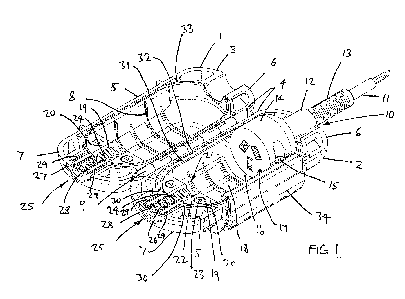
Figures 1 and 2 show a casing 1 as including two shells 2, 3 in an open
configuration. The
shells 2, 3 have generally straight sides 4, 5, curved ends 6, 7 and internal
reinforcing ribs
8. A hinge 9 connects the shells 2, 3 along a substantial length of one side 4
of each shell 2,
3.
The first end 6 has an opening 10 that receives a cable 11 and seal 12 of a
first power cord
13. The cord 13 terminates in a socket connector 14 which is fixed to the
shell 2 by
fasteners 15.
The socket connector 14 is nested on an internal wall 16 toward one end 17 of
a bay 18. A
grip mechanism 19 is housed in a compartment 20 at an opposite end 21 of the
bay 18. The
compartment 20 has a cover 22 that is fixed in place with fasteners 23. The
grip
mechanism 19 includes a central grip member 24 aligned with a port 25 in the
end 7 of the
shell 2.
A corresponding compartment 20 and grip mechanism 19 is mounted in the second
shell 3,
with an associated grip member 24 aligned with a port 25 formed in the end 7
of the
second shell 3.
A half-cylindrical seal 26 is fitted into the port 25 between the end 7 of the
shell 2 and the
grip mechanism 19. A corresponding seal 27 is provided in the second shell 3.
The seals
26, 27 internal annular sealing fins 28 and elongate lips 29 which engage when
the seals
26, 27 are pressed together.
The seal 26 also has lateral wings 30 that fit over a gasket 31 seated in a
groove 32 which
extends around an inside perimeter of the shell 2 and under both seals 12 and
26.
The second shell 3 has a blade 33 that matches the position and profile of the
gasket 31 and
seals 12, 26 in order to press against and energise the gasket 31 and seals
12, 26 when the
CA 03064606 2019-11-22
WO 2017/205935 PCT/AU2017/050538
- 7 -
shells 2, 3 are moved to a closed condition. The shells 2, 3 can subsequently
be secured
together by lock 34.
Figure 3 shows the gasket 31 is formed as a continuous strip 35. The gasket 31
is
preferably formed by of a polymeric material and is made by a process of
expanded foam
moulding so as to have favourable compression and sealing characteristics.
Since the
gasket 31 is formed as a single strip 35, there are no joins that might
otherwise cause
problems with sealing.
The gasket 31 has two sides sections 36 with shoulder sections 37 that loop
down into
cradle sections 38 at either end 39, 40. The cradle sections 38 fit into
associated channels
41 at an underside 42 of a neck 43 of each seal 12, 26. The channels 41 track
around the
neck 43 of the seals 12, 26 and then laterally under the wings 30 which taper
so that the
upper surface 44 of each wing 30 is substantially in line and flush with the
gasket 31 either
side of the seal 26.
The seal 26 may be integrally moulded with the gasket 31, however, it is
preferred the seal
26 is formed of slightly harder although still compressible elastomeric
material able to be
moulded into the more complex shape shown.
The seal 26 includes a plug 45 that is able to be pushed through a
corresponding aperture
46 in the shell, in order to secure the seal 26 in relation to the port 25.
This represents a
particularly simple mechanism for locking the seal 26 in place.
The other seal 12 is secured in place as a result of being formed as a collar
47 that is fitted
over the cord 13. A lug 48 assists in properly locating the seal 12 in the
shell 2 while the
socket connector 14 is fixed in place with the aid of through-holes 49 which
are integrally
moulded into ears 50 of the connector 14.
Figure 4a shows the fasteners 15 in the form of screws 51 which locate in
posts 52
moulded into a base 53 of the shell 2. The posts 52 are positioned behind a
wall 54 which
has raised side ledges 55 to support the ears 50 and a curved seat 56 to
support the socket
CA 03064606 2019-11-22
WO 2017/205935 PCT/AU2017/050538
- 8 -
connector 14 and provide a flush finish with the face 56 of the socket
connector 14.
Figure 4a also shows the seal 12, 26 positioned on the gasket 31, with the
wings 30
substantially flush and in line with the shoulder sections 37 of the gasket
31.
Figure 4b is an enlarged view showing the seal 26 fitted to the gasket 31,
where the
shoulder section 37 can be seen transitioning from the channel 41 around the
neck 43 of
the seal 26 and out from under the wing 30 such that the upper surface 44 of
the wing 30 is
substantially in line and flush with the gasket 31.
Figure 4c shows a similar view of the seal 12 where the gasket 31 is again
illustrated as
exiting from under the wing 30 in line and substantially flush in relation to
an upper
surface 44 of the wing 30.
Figure 5 shows a cross-sectional view of the casing 1 in a closed condition.
In that
condition, the plug 45 is located in the aperture 46 formed in shell 2 to
secure the seal 26 in
the port 25. The other seal 27 likewise has a plug 45 positioned in an
associated aperture
46 in the other shell 3. The seals 26, 27 are compressed together while a
waterproof seal is
formed between the seal 26 and the gasket 31.
At the other end 6 of the casing 1, the seal 12 is positioned such that the
lug 48 is located
in a recess 57 and the socket connector 14 is fixed in place in order for the
seal 12 to form
a second water proof seal with the gasket 31.
The grip mechanisms 19 are mounted in the respective compartment 20 in
opposing
relation and include a biasing element 58 that works between the shell 2, 3
and the grip
members 24 to exert a bias force which urges the grip members away from a base
of the
respective shell. This results in the free ends 59 of the grip members 24
being urged
toward each other. The specific form of biasing element is shown as a spring
which urges
the respective free end 59 of each grip member 24 to pivot out of the
compartment 20
however other forms of biasing may be employed as required.
CA 03064606 2019-11-22
WO 2017/205935 PCT/AU2017/050538
- 9 -
Figure 6 shows the casing 1 with a second power cord 60 and an electrical plug
connector
61 engaged with the socket connector 14 of the first power cord 13. The cord
60 passes
though the seals 26, 27 where a waterproof seal is provided by the fins 28
engaging the
cord 60.
The cord 60 also passes between the grip mechanisms 19. When the shells are
closed
together, the grip members initially yield or deflect toward the base of the
associated shell,
against the bias force of the biasing elements as a lateral closing force is
applied, in
opposition to the biasing force, to accommodate the cord. This allows for a
soft close of
the casing. However, the grip members remain biased away from the base and
still grip
opposite sides of the cord. If any axial pull-out tension is applied to the
cord the grip
members will rotate inwardly to lock onto the cord. For that purpose, the grip
members
pivot about axes positioned toward the port that extend laterally of the
shells, between first
and second sides of the respective shell. A greater pull-out tension will
generate on
increased gripping force.
The grip members 24 can have serrated surfaces 62 to further assist in
dynamically
gripping the cord 60 if any tension is applied to the cord 60, as a result of
the grip members
24 rotating in toward the cord 60 for a tighter grip. The grip mechanisms
thereby act as a
one-way stop to prevent the plug connector 61 being inadvertently pulled free
of the socket
connector 14.
As a result, when the cord 60 is connected to the first cord 13, and the
casing 1 is closed,
the cords 13, 60 will not only be waterproof sealed in the casing 1 but will
also be
prevented from separating.
With reference to Figures 7a and 7b the lock 34 is described in more detail as
a double-
acting lock to provide security against the casing 1 being inadvertently
opened.
The lock 1 has a lock body that extends a substantial distance along the side
5 of the shells
and includes a latch 63 that hooks onto a catch 64 on the shell 3.
CA 03064606 2019-11-22
WO 2017/205935 PCT/AU2017/050538
- 10 -
The latch 63 is pivotally coupled via a hinge 65 to a locking lever 66 that
nests between the
latch 63 and the shell 2. The locking lever 66 is pivoted from a second hinge
67 that
provides an over-centre mounting that requires a bias force to be overcome to
lock and
unlock the lever 66. The lever has a free end 68 that tucks into a space 69
between
external ribs 70, at an underside 71 of the shell when in the locked
condition.
The lever 66 provides additional leverage to pull the latch 63 closed and
energise the
waterproof seals inside the casing 1. By having the lock body hinged along a
substantial
length of the casing 1, together with a hinge 9 of corresponding length along
the opposite
sides 4 of the shells 2, 3, a uniform and reliable seal can be achieved.
The lever 66 is also protected from inadvertent release as it is tucked up
against the casing
1, between the ribs 70 and is held in place in the fully engaged condition by
the over-centre
mounting. A release force is needed to overcome the over-centre bias in order
to release
the lock. The release force is preferably designed to be higher than a child
is able to apply,
for safety reasons. Even if the lever 66 was accidentally released, the latch
would still
serve to secure the shells 2, 3 together and provide a secondary locking
function until the
lock lever is re-engaged.
Figure 8 shows the lock 34 in a released condition, prior to being engaged,
with the plug
connector 61 inserted in the socket connector 14. The socket connector 14 is
fixed in place
by the fasteners 15 and the plug connector 61 is fixed in the casing 1 by the
set of grip
mechanism 19, when the shells 2, 3 are closed together.
In an alternative embodiment, the casing 1 could be modified to accept a power
cord with a
simple socket head (not shown), in which case instead of the fasteners 15, a
second set of
grip mechanisms could be installed to hold each power cord in place as
illustrated in
Figure 10.
In any event, the power cords 13, 60 will be reliably gripped and held in a
waterproof
environment inside the casing 1 when the lock 34 is engaged as shown in Figure
9.
CA 03064606 2019-11-22
WO 2017/205935 PCT/AU2017/050538
- 11 -
With regard to Figure 9, although not specifically illustrated, it should be
appreciated the
shells can be formed of clear plastics in order to provide for easy visual
confirmation of the
connection state of the cords 13, 60 and an LED light or similar can be
moulded into the
socket connector 14 to show when the fist cord 13 is live.
As also shown in Figure 9, the casing 1 includes loops 72 at each end 6, 7 to
receive a
hanging hook or the like, if the casing 1 needs to be suspended from a ceiling
or rack, to
reduce potential hazard.
Additional beneficial features may include further external ribbing for
additional strength
and/or a weather-proofing secondary seal (not shown) which follows the same
path as the
gasket 31 around a perimeter of the shell 2. The secondary seal may comprises
a simple
groove in one of the shells and a matching blade on the other shell that fits
inside the
groove when the shells are in a closed configuration.
The above features all render the casing particularly suitable for connecting
power cords in
wet environments and can assist in avoiding accidents associated with the
prior art devices.
In some environments, however, the casing may be provided without the seals
that render
the casing waterproof and instead have only a weather-proof seal. The casing
may even be
manufactured without waterproof or weatherproof seals depending on the
environment in
which the casing is intended to be used, provided the casing includes at least
a suitable
lock and one or more sets of grip mechanisms in order to resist the power
cords being
pulled out of connection when the casing is closed.
It should be appreciated the grip mechanisms of the invention have grip
members that
yield or deflect to receive a power cord, in order to enable a soft close of
the casing, while
providing a dynamic grip by rotating toward the cord to increase grip pressure
in response
to axial pull-out tension in order to resist electrically connected cords
separating inside the
casing. The lever action lock then provides mechanical advantage to energise
the seals of
the casing and an over-centre mounting provides protection from inadvertent
release of the
lock.
CA 03064606 2019-11-22
WO 2017/205935
PCT/AU2017/050538
- 12 -
The soft close feature offered by the lock mechanisms means the cords can be
connected
and the casing closed without any additional manipulations of the cords, after
which the
lever action lock can be engaged with only one hand in order to provide a
secure and
reliable water proof seal around the cords.