Language selection

Search

Patent 3065737 Summary

Third-party information liability

Some of the information on this Web page has been provided by external sources. The Government of Canada is not responsible for the accuracy, reliability or currency of the information supplied by external sources. Users wishing to rely upon this information should consult directly with the source of the information. Content provided by external sources is not subject to official languages, privacy and accessibility requirements.

Claims and Abstract availability

Any discrepancies in the text and image of the Claims and Abstract are due to differing posting times. Text of the Claims and Abstract are posted:

  • At the time the application is open to public inspection;
  • At the time of issue of the patent (grant).
(12) Patent Application: (11) CA 3065737
(54) English Title: PIPE COUPLING COMPRISING A SEAL WITH INTERLOCKING LAYERS FOR RANGE OF PIPE DIAMETERS
(54) French Title: RACCORD DE TUYAU COMPRENANT UN JOINT D'ETANCHEITE AVEC DES COUCHES A VERROUILLAGE MUTUEL POUR UNE PLAGE DE DIAMETRES DE TUYAU
Status: Examination
Bibliographic Data
(51) International Patent Classification (IPC):
  • F16L 17/04 (2006.01)
  • F16L 21/02 (2006.01)
  • F16L 21/06 (2006.01)
  • F16L 25/14 (2006.01)
(72) Inventors :
  • CHIPROOT, AVI (Israel)
(73) Owners :
  • KRAUSZ INDUSTRIES LTD.
(71) Applicants :
  • KRAUSZ INDUSTRIES LTD. (Israel)
(74) Agent: NORTON ROSE FULBRIGHT CANADA LLP/S.E.N.C.R.L., S.R.L.
(74) Associate agent:
(45) Issued:
(86) PCT Filing Date: 2018-05-30
(87) Open to Public Inspection: 2018-12-06
Examination requested: 2022-06-21
Availability of licence: N/A
Dedicated to the Public: N/A
(25) Language of filing: English

Patent Cooperation Treaty (PCT): Yes
(86) PCT Filing Number: PCT/IB2018/053857
(87) International Publication Number: IB2018053857
(85) National Entry: 2019-11-29

(30) Application Priority Data:
Application No. Country/Territory Date
15/610,794 (United States of America) 2017-06-01

Abstracts

English Abstract

A pipe coupling (10) includes a clamp housing (14) and a seal assembly (12) mounted in at least one end (16) of the clamp housing (14). The seal assembly (12) includes an outer sealing layer (24) connected to an inner sealing layer (26) with interlocking mating structures (28, 30, 40, 42, 44) that abut against each other in radial and axial directions (37, 39, 41, 43) and prevent the inner and outer sealing layers (26, 24) from separating from each other in the radial and axial directions (37, 39, 41, 43).


French Abstract

L'invention concerne un raccord de tuyau (10) comprenant un boîtier de serrage (14) et un ensemble joint d'étanchéité (12) monté dans au moins une extrémité (16) du boîtier de serrage (14). L'ensemble joint d'étanchéité (12) comprend une couche d'étanchéité externe (24) reliée à une couche d'étanchéité interne (26) avec des structures d'accouplement à verrouillage mutuel (28, 30, 40, 42, 44) qui viennent en butée l'une contre l'autre dans des directions radiale et axiale (37, 39, 41, 43) et empêchent les couches d'étanchéité interne et externe (26, 24) de se séparer l'une de l'autre dans les directions radiale et axiale (37, 39 41, 43).

Claims

Note: Claims are shown in the official language in which they were submitted.

6
CLAIMS
What is claimed is:
1. A pipe coupling (10) comprising:
a clamp housing (14) comprising at least one end (16) having two opposing
clamp
members (18) and one or more tightening elements (20) for tightening said
clamp
members (18) towards each other in a direction transverse to an axial length
of said clamp
housing (14) so as to apply a radially-inward clamping force on a pipe (22)
being clamped
in said clamp housing (14); and
a seal assembly (12) mounted in said at least one end (16) of said clamp
housing
(14);
characterised in that said seal assembly (12) comprises an outer sealing layer
(24)
connected to an inner sealing layer (26) with interlocking mating structures
(28, 30, 40,
42, 44) that abut against each other in radial and axial directions (37, 39,
41, 43) and
prevent said inner and outer sealing layers (26, 24) from separating from each
other in the
radial and axial directions (37, 39, 41, 43).
2. The pipe coupling (10) according to claim 1, wherein said interlocking
mating
structures comprise an at least partially annular lug (28) that protrudes from
one of said
sealing layers (26) and is received in an at least partially annular channel
(30) formed in
the other sealing layer (24).
3. The pipe coupling (10) according to claim 2, wherein said lug (28)
comprises first
and second faces (32, 34) and is formed with a notch (40) formed at a junction
of a
slanted face (42) and a bulbous protrusion (44) of said lug (28).
4. The pipe coupling (10) according to claim 3, wherein said first and
second faces
(32, 34) are orthogonal to each other.
5. The pipe coupling (10) according to claim 3, wherein said second face
(34) is
parallel to a pipe interface surface (36) and to a contact surface (38) of
said inner sealing
layer (26), said contact surface (38) being in contact with said outer sealing
layer (24).
6. The pipe coupling (10) according to claim 3, wherein said slanted face
(42) is
opposite to said first face (32) and is slanted with respect to said second
face (34).
7. The pipe coupling (10) according to claim 3, wherein said channel (30)
of said
outer sealing layer (24) is formed with a ridge (36) that fits into said notch
(40).
8. The pipe coupling (10) according to claim 3, wherein said bulbous
protrusion (44)
fits into a complementarily shaped crevice (48) formed in said channel (30).

7
9. The pipe coupling (10) according to claim 1, wherein said inner and
outer sealing
layers (26, 24) are constructed as one contiguous piece of an elastomer.
10. The pipe coupling (10) according to claim 1, wherein said inner and
outer sealing
layers (26, 24) are not constructed as one contiguous piece of an elastomer.

Description

Note: Descriptions are shown in the official language in which they were submitted.


CA 03065737 2019-11-29
WO 2018/220556 PCT/IB2018/053857
1
PIPE COUPLING COMPRISING A SEAL WITH INTERLOCKING LAYERS FOR RANGE OF PIPE
DIAMETERS
FIELD OF THE INVENTION
The present invention relates generally to couplings (or clamps) for pipes,
and
particularly to a seal for a coupling adaptable for a range of pipe diameters,
having
sealing layers that are interlocked with each other.
BACKGROUND OF THE INVENTION
Many kinds of removable band-type couplings for pipes exist in the art. It is
noted
that throughout the specification and claims, the term "pipe" encompasses any
kind of
generally cylindrical object.
Such couplings have an elastomeric seal assembly which is tightened to form a
watertight seal against the pipe. Couplings are known that can be used for a
range of pipe
diameters. Generally, such seal assemblies have two layers of gaskets (seals),
for
example, constructed of a first ring seal seated over a second ring seal. The
seals can be
easily disconnected from one another to allow sealing against different
diameter pipes.
For smaller diameter pipes, both the first and second ring seals are used; for
larger
diameters, only one seal is used.
A prior art seal 1 of this type is shown in Fig. 1. Seal 1 includes an outer
sealing
layer 2 connected to an inner sealing layer 3 with mating portions that
include annular
ridges 4 that are received in annular grooves 5. The annular ridges 4 and
annular grooves
have a trapezoidal or triangular cross-section. There is a mating clearance
between
annular ridges 4 and annular grooves 5 to facilitate mating the two portions
together. It
has been found that such a mating structure has limited ability to withstand
forces due to
fluid pressures in the assembled coupling with liquid flowing through the
coupling. The
fluid pressures can cause the two sealing layers 2 and 3 to separate from one
another (in
the radial directions of arrows 6 and 7), and/or in the axial direction (arrow
8) along the
slant of the trapezoidal or triangular surface, at different circumferential
portions of the
sealing layers.
SUMMARY OF THE INVENTION
The present invention seeks to provide an improved seal assembly, as is
described
more in detail hereinbelow. Unlike the prior art, the seal assembly of the
present
invention has inner and outer sealing layers that mate together with
interlocking structure
that prevents the two sealing layers from separating from each other axially
and radially,
even in the presence of forces during usage of the coupling.

CA 03065737 2019-11-29
WO 2018/220556 PCT/IB2018/053857
2
There is thus provided in accordance with an embodiment of the present
invention
a pipe coupling including a clamp housing including at least one end having
two opposing
clamp members and one or more tightening elements for tightening the clamp
members
towards each other in a direction transverse to an axial length of the clamp
housing so as
to apply a radially-inward clamping force on a pipe being clamped in the clamp
housing,
and a seal assembly mounted in the at least one end of the clamp housing,
wherein the
seal assembly includes an outer sealing layer connected to an inner sealing
layer with
interlocking mating structures that abut against each other in axial and
radial directions
and prevent the inner and outer sealing layers from separating from each other
in the axial
and radial directions.
In accordance with an embodiment of the present invention the interlocking
mating structures include an at least partially annular lug that protrudes
from one of the
sealing layers and is received in an at least partially annular channel formed
in the other
sealing layer.
In accordance with an embodiment of the present invention the lug includes
first
and second faces and is formed with a notch formed at a junction of a slanted
face and a
bulbous protrusion of the lug.
In accordance with an embodiment of the present invention the first and second
faces are orthogonal to each other.
In accordance with an embodiment of the present invention the second face is
parallel to a pipe interface surface and to a contact surface of the inner
sealing layer, the
contact surface being in contact with the outer sealing layer.
In accordance with an embodiment of the present invention the slanted face is
opposite to the first face and is slanted with respect to the second face.
In accordance with an embodiment of the present invention the channel of the
outer sealing layer is formed with a ridge that fits into the notch.
In accordance with an embodiment of the present invention the bulbous
protrusion
fits into a complementarily shaped crevice formed in the channel.
BRIEF DESCRIPTION OF THE DRAWINGS
The present invention will be understood and appreciated more fully from the
following detailed description, taken in conjunction with the drawing in
which:
Fig. 1 is a simplified sectional illustration of a prior art seal assembly;
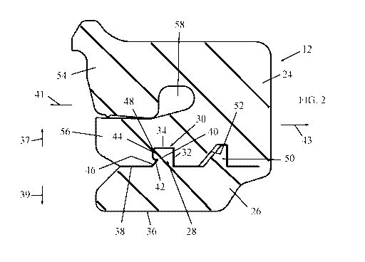
Fig. 2 is a simplified sectional illustration of a seal assembly, constructed
and
operative in accordance with a non-limiting embodiment of the present
invention;

CA 03065737 2019-11-29
WO 2018/220556 PCT/IB2018/053857
3
Fig. 3 is a simplified pictorial illustration of a pipe coupling with the seal
assembly of Fig. 2, in accordance with a non-limiting embodiment of the
present
invention;
Fig. 4 is a simplified sectional illustration of the pipe coupling with the
seal
assembly, taken along lines Iv-Iv in Fig. 3; and
Fig. 4A is an enlarged sectional illustration of the seal assembly in the pipe
coupling.
DETAILED DESCRIPTION OF EMBODIMENTS
Reference is now made to Fig. 3, which illustrate a pipe coupling 10 with a
seal
assembly 12, constructed and operative in accordance with a non-limiting
embodiment of
the present invention.
Pipe coupling 10 includes a clamp housing 14 that has one or more ends 16 (two
are shown in the illustrated embodiment). Clamp housing 14 may be cylindrical
or
partially cylindrical or of any other shape. Each end 16 is provided with two
opposing
clamp members 18 and one or more tightening elements 20 for tightening the
clamp
members 18 towards each other in a direction transverse to an axial length of
the clamp
housing 14 so as to apply a radially-inward clamping force on a pipe 22 (shown
partially
in broken lines in Fig. 2) being clamped in the clamp housing 14.
Seal assembly 12 may be mounted in end 16 of clamp housing 14. Each seal
assembly 12 is an at least partially annular seal, meaning it can be a full
360 sealing ring
or it can be a partial ring spanning an angle less than 360 , depending on the
particular
application.
As seen in Fig. 2, seal assembly 12 includes an outer sealing layer 24
connected to
an inner sealing layer 26 with at least one interlocking mating structure,
such as an at least
partially annular lug 28 that protrudes from one of the sealing layers (in the
illustrated
embodiment it protrudes from the inner sealing layer 26) and is received in an
at least
partially annular channel 30 formed in the other sealing layer (in the
illustrated
embodiment it is formed in the outer sealing layer 24). Lug 28 may include
first and
second (e.g., flat) faces 32 and 34, which are orthogonal to each other. Face
34 may be
parallel to a pipe interface surface 36 and to a contact surface 38 of inner
sealing layer 26
(contact surface 38 being the surface that contacts the inner portion of outer
sealing layer
24). Opposite to first face 32, lug 28 is formed with a notch 40 formed at a
junction of a
slanted face 42 and a bulbous protrusion 44 of lug 28. Slanted face 42 is
slanted with
respect to the second face 34 and to the contact surface 38 of inner sealing
layer 26.

CA 03065737 2019-11-29
WO 2018/220556 PCT/IB2018/053857
4
The channel 30 of outer sealing layer 24 is formed with a ridge 36 that fits
into
notch 40. The bulbous protrusion 44 of lug 28 fits into a complementarily
shaped crevice
48 formed in channel 30 of outer sealing layer 24. The interlocking mating
structures
(such as the bulbous protrusion 44 of lug 28 abutting against channel 30; the
ridge 30
abutting against notch 40 and slanted face 42) abut against each other in the
radial and
axial directions and prevent the inner and outer sealing layers from
separating from each
other in the radial and axial directions (indicated by arrows 37 and 39, and
41 and 43,
respectively, in Fig. 2), even in the presence of forces during usage of the
coupling.
The interlocking mating structures may be provided in more than one place or
in
just one place. In the illustrated embodiment, the seal assembly includes an
at least
partially annular ridge 50 is received in an at least partially annular groove
52. Ridge 50
and groove 52 may have a trapezoidal or triangular cross-section.
Figs. 4 and 4A illustrate pipe coupling 10 with the seal assembly 12 installed
therein.
Seal assembly 12, without limitation, may be made of a rubber (e.g., EPDM
(ethylene propylene diene monomer), butyl, styrene butadiene or neoprene) or a
thermoplastic elastomer (e.g., polyurethane or olefin) compatible with the
fluid to be
carried in the pipe. For example, without limitation, seal assembly 12 may be
made of
EPDM rubber with 70-80 Shore A durometer.
The inner sealing layer 26 is used together with the outer sealing layer 24
when
clamping a pipe of relatively small diameter. If a relatively large pipe is to
be clamped,
inner sealing layer 26 may be removed from outer sealing layer 24, such as by
simply
removing inner sealing layer 26 (if the two layers are not one contiguous
piece of
elastomer) or by tearing or cutting inner sealing layer 26 (if the two layers
are one
contiguous piece of elastomer). Alternatively, if the two layers are one
contiguous piece
of elastomer as in the illustrated embodiment, inner sealing layer 26 may be
folded away
from outer sealing layer 26 (instead of being torn or cut).
By "one contiguous piece of elastomer" it is meant that the two layers may be
extruded or molded as one piece or may be joined to each other, such as by
bonding,
mechanical fastening or any other suitable method.
Referring again to Fig. 2, outer sealing layer 24 may be constructed with an
outer
portion 54 folded over an inner portion 56 so as to define at least one inner
annular space
58 between and bounded by the inner and outer portions 56 and 54. The inner
annular
space 58 is in fluid communication with a fluid (e.g., water, not shown)
flowing in a pipe

CA 03065737 2019-11-29
WO 2018/220556 PCT/IB2018/053857
sealed by seal assembly 12. The fluid enters inner annular space 58 via one or
more
apertures (not shown) and applies pressure in inner annular space 58 to
increase
tightening of the seal.

Representative Drawing
A single figure which represents the drawing illustrating the invention.
Administrative Status

2024-08-01:As part of the Next Generation Patents (NGP) transition, the Canadian Patents Database (CPD) now contains a more detailed Event History, which replicates the Event Log of our new back-office solution.

Please note that "Inactive:" events refers to events no longer in use in our new back-office solution.

For a clearer understanding of the status of the application/patent presented on this page, the site Disclaimer , as well as the definitions for Patent , Event History , Maintenance Fee  and Payment History  should be consulted.

Event History

Description Date
Amendment Received - Response to Examiner's Requisition 2023-11-20
Amendment Received - Voluntary Amendment 2023-11-20
Examiner's Report 2023-09-07
Inactive: Report - No QC 2023-08-18
Letter Sent 2022-07-14
Request for Examination Received 2022-06-21
Request for Examination Requirements Determined Compliant 2022-06-21
All Requirements for Examination Determined Compliant 2022-06-21
Common Representative Appointed 2020-11-07
Inactive: Cover page published 2020-01-06
Letter sent 2020-01-06
Application Received - PCT 2019-12-30
Priority Claim Requirements Determined Compliant 2019-12-30
Request for Priority Received 2019-12-30
Inactive: IPC assigned 2019-12-30
Inactive: First IPC assigned 2019-12-30
National Entry Requirements Determined Compliant 2019-11-29
Application Published (Open to Public Inspection) 2018-12-06

Abandonment History

There is no abandonment history.

Maintenance Fee

The last payment was received on 2023-12-13

Note : If the full payment has not been received on or before the date indicated, a further fee may be required which may be one of the following

  • the reinstatement fee;
  • the late payment fee; or
  • additional fee to reverse deemed expiry.

Patent fees are adjusted on the 1st of January every year. The amounts above are the current amounts if received by December 31 of the current year.
Please refer to the CIPO Patent Fees web page to see all current fee amounts.

Fee History

Fee Type Anniversary Year Due Date Paid Date
Basic national fee - standard 2019-11-29 2019-11-29
MF (application, 2nd anniv.) - standard 02 2020-06-01 2020-05-18
MF (application, 3rd anniv.) - standard 03 2021-05-31 2021-05-18
MF (application, 4th anniv.) - standard 04 2022-05-30 2022-05-16
Request for examination - standard 2023-05-30 2022-06-21
MF (application, 5th anniv.) - standard 05 2023-05-30 2023-05-22
MF (application, 6th anniv.) - standard 06 2024-05-30 2023-12-13
Owners on Record

Note: Records showing the ownership history in alphabetical order.

Current Owners on Record
KRAUSZ INDUSTRIES LTD.
Past Owners on Record
AVI CHIPROOT
Past Owners that do not appear in the "Owners on Record" listing will appear in other documentation within the application.
Documents

To view selected files, please enter reCAPTCHA code :


To view images, click a link in the Document Description column. To download the documents, select one or more checkboxes in the first column and then click the "Download Selected in PDF format (Zip Archive)" or the "Download Selected as Single PDF" button.

List of published and non-published patent-specific documents on the CPD .

If you have any difficulty accessing content, you can call the Client Service Centre at 1-866-997-1936 or send them an e-mail at CIPO Client Service Centre.


Document
Description 
Date
(yyyy-mm-dd) 
Number of pages   Size of Image (KB) 
Claims 2023-11-19 2 87
Claims 2019-11-28 2 60
Abstract 2019-11-28 2 71
Description 2019-11-28 5 228
Drawings 2019-11-28 2 76
Representative drawing 2019-11-28 1 14
Courtesy - Letter Acknowledging PCT National Phase Entry 2020-01-05 1 586
Courtesy - Acknowledgement of Request for Examination 2022-07-13 1 423
Examiner requisition 2023-09-06 3 187
Amendment / response to report 2023-11-19 11 549
Patent cooperation treaty (PCT) 2019-11-28 1 37
National entry request 2019-11-28 4 171
International search report 2019-11-28 3 86
Request for examination 2022-06-20 5 168